Cette page fournit une simple interface de navigation pour trouver des entités décrites par une propriété et une valeur nommée. D’autres interfaces de recherche disponibles comprennent la page recherche de propriété, et le constructeur de requêtes ask.
Liste de résultats
- Setting Up Windows PC C0000422-KIT 2023 + (<div class="icon-instructions idea-icon … stuga.dokit.app/wiki/Setting_Up_C0000422-KIT_-_Full_Hardware_2023</div> </div>)
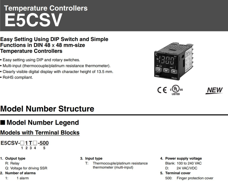
- Omron E5CVS PV Shift + (<div class="annotatedImageDiv" typeof=" …
) - Upgrading Autoflow TwinCAT2 to Win10 and TwinCAT3 + (<div class="annotatedImageDiv" typeof=" … Autoflows from A2001 to A2015 were initially produced with TwinCAT2 software. This has now been superseded with TwinCAT3 which then has the benefit of compatibility with version 6 front end software.

The original PC cannot be used because
*It is not powerful enough to run v6 front end
*The operating system cannot be upgraded to Windows 10
*It cannot be upgraded to TwinCAT3
The Beckhoff C6015 PC has been chosen to be the replacement PC. It is compact, yet powerful enough to run the v6 front end and TwinCAT in the same
. It has an upgrade to 1.9Ghz 4 core processor.
Because it has a limited 40Gb SSD memory, a compact 64Gb memory stick is inserted into the USB 3.0 port. This acts as a separate drive for the DDRIVE dynamic storage for all machine setup. The internat drive is for the Operating System only. This mimics the current Autoflow setup of a remote Camera PC, hence the camera PC can be retired after the upgrade
era PC, hence the camera PC can be retired after the upgrade<br/>) - Autoflow Maintenance - Gripper + (<nowiki>The following preventative m …
The following preventative maintenance tasks should be carried out regularly on the machine. The frequency depends on the machine use, but as a guide: i-Weekly<br />20 Hrs/Week Monthly</pre></div></nowiki>)2-3 Shifts Weekly
40 Hrs/Week Bi-Weekly
20 Hrs/Week Monthly - Autoflow Maintenance - Infeed + (<nowiki>The following preventative m …
The following preventative maintenance tasks should be carried out regularly on the machine. The frequency depends on the machine use, but as a guide: kly<br />20 Hrs/Week Monthly</pre></div><br/></nowiki>)2-3 Shifts Weekly
40 Hrs/Week Bi-Weekly
20 Hrs/Week Monthly - R0015030B Bench assemble loader wheel + ('''<u>Tools Required</u>''' … '''Tools Required''' Standard hex keys Standard spanner set Cutting blade Rule External circlip pliers Switch setting box Ball pien hammer '''Parts Required''' D0015438 x 1 D0010431 x1 B0000426 x 1 B0000173 x 7 D0010238 x 1 B0000046 x 2 D0015741 x 1 D0015439 x 1 M0001077 x 1 D0010509 x 1 D0015436 x 1 D0010611 x 1 P0001044 x 1 P0001098 x 1 P000001174 x 1 P0000200 x 1 P0001198 x 1 P0001047 x 1 P0001041 x 1 P0001042 x 1 B0000240 x 1 B0001100 x 2 D0015435 x 1 B0000053 x 1.2 B0000054 x 2 D0015434 x 1 B0000189 x 1 B0000142 x 1053 x 1.2 B0000054 x 2 D0015434 x 1 B0000189 x 1 B0000142 x 1)
- R0015253 Fit Slider units + ('''<u>Tools Required</u>''' Standard spanner set '''<u>Parts Required</u>''' Pre built Slide units)
- R0015004 Bench Assemble Gripper + ('''<u>Tools Required</u>''' E … '''Tools Required''' External circlip pliers Standard Hex key set Standard spanner set Reed switch setting box Hammer Standard screwdriver set Rule '''Parts Required''' B0001106 x 20 D0015095 x 8 D0015096 x 2 D0015086 x 1 B0000034 x 2 D0015084 x 2 D0015083 x 1 D0015082 x 1 E0000366L x 1 B0001182 x 2 M0001182 x 2 D0015756 x 1 P0001013 x 1 P0001041 x 1 P0001128 x 1 P0001198 x 2 P0001120 x 1 D0015431 x 1 B0000437 x 1 D0015430 x 1 D0015090 x 2 D0015085 x 1 D0015102 x 2 D0015103 x 2 D0015104 x 2 D0015170 x 2 P0000049 x 1 D0015097 x 2 D0015100 x 2 D0015292 x 1 E0000336 x 1 E0001069 x 1 A0001044 x 4015100 x 2 D0015292 x 1 E0000336 x 1 E0001069 x 1 A0001044 x 4)
- R0015041 Bench Assemble Top Hood Assembly + ('''<u>Tools Required</u>'''
… '''Tools Required'''
Standard hex key set
Standard spanner set
Standard Hss drill set
Standard tap set
Acoustic foam cutting board and straight edge
Utility Blade
'''Parts Required'''
Pre wired light, beacon and network cable from electrical department
C0001152 Camera: HikVision DS-2CD2343G0-I-2.8mm x 1
C0001239 Micro SD Card 32Gb Class 10 x 1
D0000770 Door Hinge (M0016) x 2
D0001877 Saw Top Door Mk4 x 1
D0004641 Hinge Pin Block (D7445) x 1
D0004642 Flap Counterbalance Bar x 1
D0004645 Safety Flap Hinge Pin x 1
D0004679 Flap Stiffening Bar x 1
D0004705 Flap Hinge Bar x 1
D0004747B top door screen x 1
D0004807 Flap x 1
D0007445 Hinge Pin Block OH (D4641) x 1
D0016251 Saw Hood Switch Mount Plate (Bernstein) x 1
E0000275 Button: Base Fixing 1 N/C x 1
E0001072 Emergency Stop Module Bevelled 1NO 1NC x 1
E0001569 Guard Lock Switch: Bernstein Radius Actuator (Key) x 1
H0004643 4mm Axxis Clear 145mm x 690mm x 1
M0000002 12mm Grey Acoustic Foam with Black PVC Facing x 1 (consumable stock )
M0000036 Sign - Ear Protection x 1
M0000048 Gas Spring 15mm x 100mm x 1
M0000539 Handle Black Nylon 200mm M8 Fixings x 1
100mm x 1 M0000539 Handle Black Nylon 200mm M8 Fixings x 1 <br/>) - R0015337 Bench Assemble Guarding Components + ('''<u>Tools Required</u>'''
… '''Tools Required'''
Standard hex key set
Standard spanner set
Standard HSS drill set
Acoustic mat cutting board and straight edge
Utility blade
'''Parts Required'''
D0000770 Door Hinge (M0016) x 2
D0001886 Front Door Saw Mk 4 x 1
M0000002 12mm Grey Acoustic Foam with Black PVC Facing x 1
M0000539 Handle Black Nylon 200mm M8 Fixings x 1
M0000031 panel edging ( consumable stock )
M0000150 Stuga sticker clear x 1
M0000154 Stuga service sticker x 1
uga sticker clear x 1 M0000154 Stuga service sticker x 1 <br/>) - Stuertz Infeed - Freeing Roller under Gripper Arm + ('''Applies to: A2026-A2030 Autoflow Mk4 wi … '''Applies to: A2026-A2030 Autoflow Mk4 with Jetta Locking motors'''
In certain circumstances, the forward clamp roller arm has stuck itself under the gripper arm. Freeing from this situation requires a set process because the GZ axis motor is braked and probably in an overload condition
nfident in using TwinCAT on the VM machine to navigate to settings</div> </div><br/>) - Laser Setup on Flowline/ZX3 for Laser Holes + ('''How to Setup .'''
This will Cover the … '''How to Setup .'''
This will Cover the Basic Alignment of the receiver and Sender setup.
Focusing the Laser and Setting up the Receiver Sensitivity.
Always Make sure Laser Sender and Receiver are clean and both lenses have been wiped with a soft cloth first.
en wiped with a soft cloth first. <br/>) - TB0314 Updating Mint File in Workbench + ( * Updating software can be very complicat … * Updating software can be very complicated, so care must be taken and always ensure there is a route to retrace your steps in the event of a failure – with Baldor .mnt files this is easy because each version is a separate file and therefore easy to load the old one back in again * In general, the Baldor (.mnt) software has been designed to be backwards compatible, but there are a few steps that needed to be taken that made this impossible. In these cases, the front end software (winMulti or winSaw) also needs to be updated – you will get an error to tell you that this is the case * Version numbers have always followed a numerical order, so the higher the number, the later the version * Mnt files should always be stored in ** c:\multi on MH side – called Multi X.xxx.mnt ** c:\saw on Saws or Saw side of flowline – called IgSaw X.xx.mnt aw side of flowline – called IgSaw X.xx.mnt )
- TB0390 Fitting SR Datum Sensor + (<br/>
<table class="wikitable" bo …
3" valign="top">F0000059 </td><td width="359" valign="top">M8 Washer </td><td width="73" valign="top">2 </td></tr><tr> <td width="104" valign="top">'''9''' </td><td width="123" valign="top">F0000014 </td><td width="359" valign="top">M6 x 20 SKT CAP SCREW </td><td width="73" valign="top">2 </td></tr><tr> <td width="104" valign="top">'''10''' </td><td width="123" valign="top">F0000028 </td><td width="359" valign="top">M8 x 50 SKT CAP SCREW </td><td width="73" valign="top">2 </td></tr></table>)'''Item Number''' '''Part Number''' '''Description''' '''Qty''' '''1''' D0015489 Saw Turntable Sensor Bar 1 '''2''' D0015490 Saw Turntable Sensor Flag 1 '''3''' D0015491 Saw Turntable Flag Bracket 1 '''4''' E0000336 8mm Threaded Proximity Sensor 1 '''5''' E0000337 M8 90° Lead 1 '''6''' F0000543 U Bolt 3” with Nuts 1 '''8''' F0000059 M8 Washer 2 '''9''' F0000014 M6 x 20 SKT CAP SCREW 2 '''10''' F0000028 M8 x 50 SKT CAP SCREW 2 - Create a TwinCAT Project from Scratch + (<br/><div class="icon-instructions info-icon"> <div class="icon-instructions-icon"><i class="fa fa-info-circle"></i></div> <div class="icon-instructions-text">...Beckhoff Technical help is available on 01491 410539 option 3</div> </div> <br/>)
- TB0426 Replacement Zebra Printer Setup + (<div class="icon-instructions caution-i … [https://stuga.dokit.app/wiki/TB0452_ZD620_Zebra_Printer_Setup ZD620 Instructions]iv> [https://stuga.dokit.app/wiki/TB0452_ZD620_Zebra_Printer_Setup ZD620 Instructions])
- Updating winStugaSaw Software to v4 + (<div class="icon-instructions caution-i …
With the upgrade of the source code editor to Visual Studio 2017, and the associated security changes to Windows, many thing changed with the Windows .net libraries. In order to maintain the code, it needed to be upgraded.
This upgrade had major consequential effects:
# It was not compatible with windows XP any more due to security issues
# A new version of Workbench needs to be installed
any more due to security issues # A new version of Workbench needs to be installed <br/>) - DM - Updating Resources + (<div class="icon-instructions caution-i …
All information provided to the service engineers on Device Magic can all be linked to a single Excel document. This document provides all customer names, machine numbers, emails and employee information. Linking this document with Device Magic provides fields that make it easier for engineers to fill out the form.
used internally at Stuga and not be sent to engineers or customers in coordination with Data Protection standards.</div> </div><br/>) - ZX5 Installation Procedure + (<div class="icon-instructions caution-icon"> <div class="icon-instructions-icon"><i class="fa fa-exclamation-triangle"></i></div> <div class="icon-instructions-text">...Read the risk assessment and method statements before proceeding.</div> </div>)
- OBSOLETE Installing SourceTree Version Control Software + (<div class="icon-instructions caution-i … Use this [https://stuga.dokit.app/wiki/Changing_Version_Control_to_Visual_Studio link] From Jan 2020, Sourcetree will be increasingly used to properly maintain changes to the Stuga source code. Each machine with TwinCAT3 will need the Sourcetree program installed, and a change to where and how the source code is stored This tutorial deals with installing the Sourcetree program from Atlassian code is stored This tutorial deals with installing the Sourcetree program from Atlassian)
- TB0409 Setting Up Windows 10 PC 2018 + (<div class="icon-instructions caution-i … Please use [[Setting Up Windows PC C0000422-KIT 2023]][[Setting Up Windows PC C0000422-KIT 2023]])
- Commissioning a Beckhoff Axis + (<div class="icon-instructions dont-icon"> <div class="icon-instructions-icon"><i class="fa fa-hand-paper-o"></i></div> <div class="icon-instructions-text">...Any stepper motor drives will need the EP7041 drive to be programmed first</div> </div>)
- R0015336 Pneumatic Output Testing Part 2 + (<u>'''Tools Required'''</u> PCL airline connection 12mm blanking ports Valve Manual over ride tool Standard screwdriver set Additional colleague when setting regulator pressures for outputs <u>'''Parts required'''</u> R0015040 completed module)
- R0010260 Bench Assemble Tool Break Sensor + (<u>'''Tools Required'''</u>
… '''Tools Required'''
Standard tap set
Standard drill set
Standard hex key set
Pipe cutters
Flush cutters
M0001053 Stock 6mm copper tube
M0000153 small Stuga sticker
'''Parts Required'''
A0001046 P Clip 6mm Steel / Rubber Liner x 6
D0001962 Tool Sensor Mount x 1
D0001963 Tool Sensor Post x 1
D0001964 Tool Sensor Logo Plate x 1
E0001120 Sensor: Ultrasonic M8 20-150mm x 1
E0001082 4 pin m8 sensor single ended x 1
P0000046 Fitting: 'Y' Adaptor 6mm x 1
P0000149 6mm to 4mm reducing stem x 2
P0000160 Fitting: Flow Controller In Line 6mm x 1
P0000456 Compact straight male adapter 4mm- M5 x 2
m x 1 P0000456 Compact straight male adapter 4mm- M5 x 2 <br/>) - R0015292 Install Cylinder Rails and Align + (<u>'''Tools Required'''</u> … '''Tools Required''' Standard spanner set Standard hex key set Tape measure Wire line Pneumatic cylinder setting jig '''Parts Required''' R0015288 Bench Assemble Transfer slid units and cylinder rails R0015093 Bench Assemble Transfer Beamd units and cylinder rails R0015093 Bench Assemble Transfer Beam)
- R0015279 Align Backfences + (<u>'''Tools Required'''</u> Standard hex key set Standard spanner set Wire Line setting equipment 600mm rule Workshop Gripper setting jig 2 meter straight edge <u>'''Parts Required'''</u> Fitted and Levelled roller bed assemblies)
- R0015310 Install V Notch Subframe + (<u>'''Tools Required'''</u> … '''Tools Required''' Standard hex key set Standard Spanner set Parallel setting blocks 600mm rule 1 meter straight edge 2 meter straight edge 12 " engineers level 12" engineers square '''Parts Required''' D0015151 Shaft End Washer x 8 D0015155 Vertical Spacer Bar x 4 D0015150 shaft 40mm zx v notch x 4 D0015169B cylinder rod bracket x 2 R0015035 Bench Assemble V Notch Componentsinder rod bracket x 2 R0015035 Bench Assemble V Notch Components)
- R0015336 Pneumatic Output Testing + (<u>'''Tools Required'''</u> … '''Tools Required''' PCL airline connection 12mm blanking ports Valve Manual over ride tool Standard screwdriver set Additional colleague when setting regulator pressures for outputs '''Parts required''' R0015040 completed modulet;u>'''Parts required'''</u> R0015040 completed module)
- R0015321 Bench Assemble Guards and Doors + (<u>'''Tools Required'''</u>
… '''Tools Required'''
Standard hex key set
Standard spanner set
Dymo label printer
'''Parts Required'''
C0001152 Camera: HikVision DS-2CD2343G0-I-2.8mm x 3
C0001239 Micro SD Card 32Gb Class 10 x 3
D0007643B Perspex Glazing - Door x 4
D0007644B Machining Centre Door 1 x 2
D0007645B Machining Centre Door 2 x 2
D0007654B Perspex Glazing - Front Guard MkB x 1
H0015747 8mm diameter rod x 1 ( in process of changing to D0015747 x 4 )
M0000036 Sign - Ear Protection x 1
M0000201 T Handle Cabinet Lock x 2
gn - Ear Protection x 1 M0000201 T Handle Cabinet Lock x 2 <br/>) - TB0444 Renewing CF Card on TwinCAT2 Systems + (<u>Problem</u> These machines … Problem These machines use a CX5020 PC with a 2Gb CF card running TwinCAT2 PLC system. The CF card can fail, which is effectively the windows operating system. The CF card has a very small capacity, so needs to be created from an image. This TB outlines the steps in the process to ensure a successful conclusion. 1. Create a new CF card at stuga using the beckhoff imaging tool on a CX5020 2. Boot up with the CX5020 3. Ensure PLC is set to Enable on start-up (default is config mode) 4. Rename the PC 5. Install TeamViewer host v10 or less from a USB stick 6. If you have a copy of the version of winMulti it was running, copy this in to the c:\ multi folder. If not, a “'''''new version install'''''” will be needed so copy in data from the g:\builds\PC Installs\Autoflow\Multi folder 7. Set up and customer specific network parameters to ensure TeamViewer will work when it is plugged in on site 8. Send to customer Once on site, follow procedure A if the winMulti version is preserved, or B if it is a '''''new version install'''''eserved, or B if it is a '''''new version install''''')
- TB0449 Ecoline Clearing out Old Archived Data + (= Problem = Software takes a long period of time to find bar after scanning barcode.)
- TB0428 Connecting To Yaskawa with Silex USB + (== What is the Silex DS-510? == The Silex … == What is the Silex DS-510? == The Silex unit is a USB server, allowing a PC to have a USB port anywhere over an ethernet network. This is useful to connect the PC to a Yaskawa inverter when they are located in different cabinets. The software sets up a virtual USB port which can then be used to run the Yaskawa DriveWorks software.ed to run the Yaskawa DriveWorks software.)
- R0015011 Bench assemble Gripper + (==Introduction==
'''<u>Tools Require … ==Introduction==
'''Tools Required'''
External circlip pliers
Standard Hex key set
Standard spanner set
Reed switch setting box
Hammer
Standard screwdriver set
Rule
'''Parts Required'''
B0001106 x 20
D0015095 x 8
D0015096 x 2
D0015086 x 1
B0000034 x 2
D0015084 x 2
D0015083 x 1
D0015082 x 1
E0000366L x 1
B0001182 x 2
M0001182 x 2
D0015756 x 1
P0001013 x 1
P0001041 x 1
P0001128 x 1
P0001198 x 2
P0001120 x 1
D0015431 x 1
B0000437 x 1
D0015430 x 1
D0015090 x 2
D0015085 x 1
D0015102 x 2
D0015103 x 2
D0015104 x 2
D0015170 x 2
P0000049 x 1
D0015097 x 2
D0015101 x 2
D0015292 x 1
E0001069 x 1
A0001044 x 4
7 x 2 D0015101 x 2 D0015292 x 1 E0001069 x 1 A0001044 x 4<br/>) - TB0415 Method to Prevent Loosening of Saw Blade + (==Problem==
On Z063 the bolt holding the s … ==Problem==
On Z063 the bolt holding the saw blade onto the spindle has regularly been loosening during use.
==Solution==
The M16 bolt will be replaced with a stud and castle nut that can be locked with a cotter pin.
==Tool List==
Drill with Ø5.0 bit
24mm Spanner
C Spanner
= Parts List =
0000549 </td><td width="319">Split Pin 4mm x 32 </td><td width="302">1 </td></tr><tr valign="TOP"> <td width="76">F0000550 </td><td width="319">Castle Nut M16x1.5 </td><td width="302">1 </td></tr></table>)D0004031B Saw Washer 3mm 1 D0015560 Spindle Stud 1 F0000273 Spirol Pin Ø6 x 30 1 F0000549 Split Pin 4mm x 32 1 F0000550 Castle Nut M16x1.5 1 - Correcting Linearity with Rack Offset File + (Accuracy problem on A2001 was traced to a … Accuracy problem on A2001 was traced to a non-linear rack. This tutorial demonstrates how to test the linearity of a rack and the systems in place to correct the linearity. machine in the 20 year history that has needed these alterations</div> </div>)
- R0000728 R0000729 Stroke Assembly Dismantling + (Assemblies fitted to MK1 ZX4 will require … Assemblies fitted to MK1 ZX4 will require refurbishment at some point of life cycle.
The following instructions should be followed to ensure that correct assembly and setting are performed
'''Tools Required'''
Standard hex key set
Standard spanner set
Double pin saw flange spanner
Drifts and punches
Ballpein hammer
Soft hammer
Degreasing bath
pein hammer Soft hammer Degreasing bath <br/>) - Z Transom Width Measurement + (Difficulty can be had when trying to accurately measure the width of a Z transom profile section. This guide will show you how to accurately measure the width of the Z section to within 0.1mm which is required when setting up Y notching accurately)
- Placing a TwinCAT3 Machine Under Source Control + (<div class="icon-instructions caution-i … Click [https://stuga.dokit.app/wiki/Changing_Version_Control_to_Visual_Studio here] for the latest procedure For many years, the source code for the PLCs has resided on the G:\drive and then a copy on each and every one of the PCs used to edit the code, so at least one on each machine. This is a recipe for disaster because maintaining all the copies and version numbers is incredibly difficult and adds a lot of time overhead to fixes and changes. This has worked because there has been only one developer, but this is set to change in future as more programmers will be trained and tracking versions becomes more difficult From 2020, the PLC code version control has been improved by using an industry standard source control system called "Git" along with "BitBucket" to store the PLC code in the cloud. The program "SourceTree" is used to commit, push and pull the changes [https://www.atlassian.com/git/tutorials/what-is-version-control Click here] for an introduction to version control using Git This tutorial is a step by step guide to setting up an existing machine or diagnostic PC to a standard uses on all Stuga machines to enable quick, easy and stress free version control.standard uses on all Stuga machines to enable quick, easy and stress free version control.)
- Upgrading Project File on TwinCAT2 System + (How to upgrade the .pro file (project) on … How to upgrade the .pro file (project) on a Beckhoff TwinCAT2 system
ram called "TwinCAT PLC Control" to download the PLC project</div> </div><br/>) - Full Version Upgrade TwinCAT3 WinMulti + (If a PC fails on a machine in the field an … If a PC fails on a machine in the field and the hard drive data cannot be recovered, it is necessary to replace the PC. This may create a version conflict, as the new PC will have later versions of twinCAT installed than the original
This tutorial outlines the steps required to bring all the machine systems up to the latest level to ensure compatibility
ions-text">...This is a one-way process that cannot be reversed</div> </div><br/>) - Disabling a Tool Home or Tool Out Sensor + (If there is a failure of a tool out or too … If there is a failure of a tool out or tool home sensor on the Stuga spindle ring, it is important to be able to quickly disable the input so the machine can continue production until the problem can be properly resolved. The software has an inbuilt functionality to do this - this tutorial takes you through the necessary stepsrial takes you through the necessary steps)
- Create a TwinCAT Project from Existing Project + (If you are confident and proficient in usi … If you are confident and proficient in using the Visual Studio editor to create TwinCAT projects, you can shortcut a lot of the data inputting by copying and modifying an existing project. This will keep the naming conventions and links exactly the same
ne has exactly the same EtherCAT box, drive and module setup</div> </div><br/>) - Changing Version Control to Visual Studio + (In March 2022 the password policy of the s … In March 2022 the password policy of the system behind SourceTree / Bitbucket and Atlassian changed - [https://community.atlassian.com/t5/Bitbucket-articles/Announcement-Bitbucket-Cloud-account-password-usage-for-Git-over/ba-p/1948231 link]. This meant all machine would need a complex password login change for the SourceTree program used for version control of the PLC code. This was not straight-forward to resolve, so the decision was made to change the version control system to the one that is packaged with the Visual Studio system by default. This is a better method anyway, but it needs the "TcXaeShell" installed. Visual Studio that includes Source control, rebadged for TwinCAT3</div> </div>)
- Commissioning - Off-Cut Laser Sensor + (Infeed Off-Cut Laser sensors are used to c … Infeed Off-Cut Laser sensors are used to check the length of profile with the proposed length from the software. This is to avoid incorrect lengths and profiles being cut. The sensors will be put at specific lengths along the infeed which will be input in the software files. When profile hits the back fence all covered sensors will trigger, hence, the profile must be larger that the final triggered sensor.be larger that the final triggered sensor.)
- TB450 - CMOS Battery replacement + (Internal CMOS batteries are used in PCs to … Internal CMOS batteries are used in PCs to keep a constant power supply to BIOS memory while the main power supply is switched off. These batteries should last up to 5 years when a PC has been left idle. Sometimes these batteries can fall flat before this time either due to being low when sent out or extended use on older machines. The main symptom of a CMOS battery faulting on a Stuga machine is the PC not booting up when mains power is switched on which will be indicated by a “No Signal Detected” message being displayed on the screen. This is due to the BIOS setting “Restore AC Power Loss” going back to its default value of OFF due to the battery faulting. Restoring the BIOS to its original settings is a temporary fix in this situation as it is most likely this will happen again a couple of months down the line (See TB 376 or 213). The battery required is a '''CR2032'''. In the case of the Antec PC, and most commonly, the battery is held in an open housing that can be pushed to release and easily replaced. In PCs such as the Acer Revo the battery needs to be pre-wired with a plug but still easily unclipped and replacedug but still easily unclipped and replaced)
- Stuertz Infeed - Check GY Position Parallelism + (It is important that the parallelism of th … It is important that the parallelism of the GY axis to the backfence is set and maintained along the length of the rack. This tutorial describes how to check this parallelism without the need for measuring equipment
Potential Symptoms of a problem
*Gripper cannot pick up offcuts
*Gripper /profile end forced away from backfence
*Accuracy problems
*Gripper wobbles after it has released profile
Use the laptop to enable you to control the Service screen whilst inside the infeed table
Ther gripper setting jig is used to give an accurate and reliable zero to locate the gripper jaw to. Any piece of aluminium reinforcing box section will also work
Create a spreadsheet or a table to log your results,.
ng box section will also work Create a spreadsheet or a table to log your results,. <br/>) - Setting Gripper Nose + (It is very important to ensure the gripper nose and heel is correctly set up. This assembly is subject to a lot of wear and tear and maintenance is very important. Incorrect setting or play in this assembly is a major cause of accuracy issues)
- ZX5 Installation Procedure 2023 + (Key data for installation of ZX5 Dokit to generate consistency of installation Quality checks for installation Manufacturing data supply)
- Autocut Piece Jammed + (Let's say a small piece has become wedged … Let's say a small piece has become wedged between the eject table and the outfeed table frame.
ach into the machine until it is safe to do so - Press ESTOP</div> </div><br/>) - Monday - Emails to Updates + (Mondays has changed the way it deals with … Mondays has changed the way it deals with the way it writes updates via email, in a very useful way for us. This will save a lot of time cutting and pasting information from emails. Simply put, * when you send an email, cc: the unique email address for the item in your email you are sending. This is standard practice to get your email into Mondays. * When your contact replies (with reply all) * their reply will now magically appear in the Monday update for the item. * It even strips out the email trail, leaving just the important reply It used to be the case that only members of Stuga.co.uk could send an email directly to an update, but this has now changed…ly to an update, but this has now changed…)
- Move SR Datum Sensor to Higher Level R0019217 + (On a Mk4 Autoflow, The SR axis daum sensor … On a Mk4 Autoflow, The SR axis daum sensor is originally located at the rear and to the base of the SR axis. This area is prone to offcuts, so a new location has been designed at the top, with the following design parameters
*Easy to retrofit
*Sensor is protected in a case
*Short distance to connection box
*Uses existing mounting holes
*Easy to adjust and maintain
*Sensing end location should be vertical onto a plate, not horizontal on to a radiused surface
*Can use E0000336 2mm range sensor reliably
*Incorporate a front fence to help deflect offcuts down the chute and to protect the sensor
The parts are supplied in Kit R0019217B
illustrated here are from a Right to Left feed machine. Parts are unhanded so can be fitted to either hand machine</div> </div><br/>) - ZX5 V Notch Blade Mechanical Setup + (On previous models the V notch separation … On previous models the V notch separation was set via the software. This could be quite time consuming and required multiple tests and measurements to get it right. Four variables were used for each V notch and it is not straight-forward to get the shape, depth and position correct. On the new ZX5 the '''shape''' of the V notch is set mechanically and once set it should never need changed again, but remember that some customers sharpen their V notch blades instead of replacing them. The following was carried out on the rear V notches using some standard outerframe but the process is exactly the same for the front. Once set you can use the usual software settings to increase/decrease depth and to align back to back. The overall process is: # Set the shape of the V notch (Mechanical adjustment) # Set the Depth of the V notch (Software adjustment in Notching Tab) # Set the Position of the V notch (Software adjustment in Notching Tab) you will be in close proximity to the V notch blades and tooling.</div> </div>)
- Device Magic - Adding a Device Email Address + (PM service and service call reports will b … PM service and service call reports will be sent to the engineer's own email address automatically, but '''''only if''''' the device "Email" property is set up correctly.
This needs to be done separately using a device magic account.
's device is renewed or needs to be re-added in Device Magic</div> </div><br/>) - CX5120 Replacement + (Replacement of Beckhoff CX5120 Skill Lev … Replacement of Beckhoff CX5120 Skill Level: Experience with Twincat & Visual Studio n’t Switch CF cards around. Keep them in the CX5120’s they came with.</div> </div>)
- Setting Infeed Loading Wheel + (Setting the pressure and clutch tension on … Setting the pressure and clutch tension on the loading wheel is critical for the reliable and accurate running of the machine If set incorrectly, the profile will slip and not load correctly or will not give an accurate start position for the datum holes The goal is to set the system to a "goldilocks" zone where there is enough pressure and clutch tension to reliably load a bar, but not too much so the clutch limits any correctional movement from the gripper arm on loading e video demonstrates how easy it is for the wheel to become loose</div> </div>)
- Setting Profile Detection Laser Sensor + (Setting the profile sensor correctly is im … Setting the profile sensor correctly is important as it will lead to incorrect offcut measurement.
ensure the sensor is set for the range of different colours</div> </div><br/>) - TB0425 Lenovo Tablet Setup + (Setting up all apps for the engineers Lenovo tablets.)
- Changing Main Saw Blade + (Stuga recommends this blade be changed aft … Stuga recommends this blade be changed after 1-2 weeks of cutting - symptoms to determine if the blade needs changing:
* Awful cutting sound / smell
* Profile dragging (sizes too short)
* Brown burnt swarf
* Smoke coming out of profile end while cutting
p and can be awkward to manouver out of the saw, please be careful</div> </div><br/>) - Beckhoff AX8000 Flowline Upgrade + (The Flowline range (Mk3, ZX3, ZX4) are Stu … The Flowline range (Mk3, ZX3, ZX4) are Stuga built and designed machines for prepping and cutting uPVC windows and doors. The Flowline is the first machine of the Stuga 'U' shaped machines which has prepping and cutting working in the same machine package. The Flowline is still a fantastic machine for the industry, however, due to the age of the machines and older control systems becoming obsolescent, we have had to find an upgrade route that does not only keep the machine going, but also provides improvements from the original model and up-to-date technology to future proof the machine. The upgrade that we have developed for the Flowline is supplied from an automation supplier named Beckhoff. We also use Beckhoff on our new build machines. This gives us better lead times, more understanding of the products and better diagnostics/ support for our customers. The drive system that we use is called the AX8000 series. These drives are a compact multi axis servo system that use an EtherCAT interface and STO safety functions. These servo drives, coupled with Beckhoff AM8*** series OCT servo motors provide quicker installations and all round performance increases from any system we have previously used. To drive all of the new system, we are using a Beckhoff IPC controller that runs TwinCAT 3. This links into the system via EtherCAT. All of the machine can now link together via EtherCAT to provide quick and stable communications. This tutorial will give you step by step guides on the physical upgrade requirements needed when upgrading a Flowline Mk3 to a Flowline Mk3 with Beckhoff AX8000 Control. Each step will provide you with written information and pictures to guide you through the upgrade. Each step will contain necessary information which will also provide you with rationale for the design and an idea of the benefits over using different methods. Please always feel free to provide Stuga with any feedback on this document or its contents.feedback on this document or its contents.)
- Stuga Product Database - Edit Product Data + (The Stuga website has a parts database, much like a shop front for helping identify Stuga Machine parts. Keeping the data updated and logging nuggets of useful information is invaluable in helping identify parts on machines)
- Upgrade ZX Machine to Beckhoff Drives and Control + (The ZX3 and ZX4 machines that have control … The ZX3 and ZX4 machines that have control systems that pre-date the Beckhoff hardware now have an upgrade available. The upgrade will bring up-to-date hardware to the machines control system and drives. The control system and drives will be changed to Beckhoff. TwinCAT 3 PLC and AX8000 series drives.f. TwinCAT 3 PLC and AX8000 series drives.)
- TB0447 ZX5 Setup - X Axis Beam Calibration + (The ZX5 has a moveable Beam on the Z axis. … The ZX5 has a moveable Beam on the Z axis. The design reason behind this is to keep the gripper arm short for reliability and stiffness, yet enable it to move out of the way for rear V notching During the calculations for the machining bar recipe, the software has to work out if and when the beam needs to be moved: · If there are no v notches on the bar, then machine all the operations without moving the beam. Beam moves at the very end when ejecting · If there is a V notch, move the bar during the first X axis position where position > beamStrokeLength Therefore, it is very important for the software to know how far the beam moves physically to offset all the positions to allow for it. The distance is measured and entered into parameter beamStrokeLength. It should be around 700mm. beamStrokeLength. It should be around 700mm.)
- ZX5 Adjusting V Notch Depth and Position + (The ZX5 has a twin blade system for the V … The ZX5 has a twin blade system for the V notches that is designed to be easier to set up. The overall process is: # Set the shape of the V notch (Mechanical adjustment) # Set the Depth of the V notch (Software adjustment in Notching Tab) # Set the Position of the V notch (Software adjustment in Notching Tab)otch (Software adjustment in Notching Tab))
- TB0445 ZX5 Setup - Infeed Measure Sensor Calibration + (The ZX5 has two bar measuring systems – th … The ZX5 has two bar measuring systems – the side laser and the sensor array. The side laser scans the bar as it moves into the final loading location, which gives the software a “heads-up” for the length of the bar. If the length is different to expected, the software will then use the sensor array to measure the bar length. There are 2 measurement methods because the side laser is not 100% reliable, especially on shorter lengths below 3000mm. However, it does mean the system does not have to grip and measure / reoptimize each bar length, so improves the cycle time. The sequence is as follows 1. During the conveyor loading, measure the length using the side laser 2. Once loaded to backfence, check the backfence sensor array. 3. If the sensor array rough measurement does not match the laser – a. If the laser measured length < infeedLaserRemeasure, continue and measure with rear sensors b. If the laser measured length < infeedLaserRemeasure, flag an error that laser has not measured correctly. c. If it does match, use the laser value to reoptimize the bar if it is different than expected 4. Load and Grip bar, if necessary, measure accurately with rear sensor arrayssary, measure accurately with rear sensor array)
- Setting Arrow Heads on ZX5 or ZX5-E + (The Zx5 and Zx5e have an upgraded system o … The Zx5 and Zx5e have an upgraded system on the saw centralising which takes the best mechanical features of the standard saw centralising, yet adds an ability to move the central point for Y notches.
In general, this makes it easier to set up, because the overall centralise position can be changed in software , rather than adjusting a cylinder offset, and also to fine tune the centralise position for different profiles
the arrow head position permanently will also alter Y notch depths</div> </div><br/>) - TM018B Microline and ZX3 V Notch Blade Setup + (The engineer will need a reasonable mechan … The engineer will need a reasonable mechanical knowledge, and a working knowledge of the operation of the machine. You will need callipers (+/-0.05mm) and an accurate rule The setting of the V notch blades on a ZX3 Ring revolves around the setting of two groups of parameters: *V and W axis positions *Blade offsets for each blade The rough position of V and W axes is set first, then the individual blade offsets are set, and finally a test is run to tweak the accuracy to gain perfection. There are two “tweaking” parameters for each blade. The two parameters are: *Depth offset – how deep into the bar *X axis offset – position of point of blade relative to the spindle centrelinef blade relative to the spindle centreline)
- TB0422 Commissioning ZX5 Software 2018 + (The first step in commissioning a new mach … The first step in commissioning a new machine is to get the basic software setup correctly installed. Because the software is designed to be very flexible across many machine types, the simplest way to do this is to copy from a recently built similar machine.opy from a recently built similar machine.)
- R0000299 Stroke assembly rebuild Part 2 + (The following instructions should be follo … The following instructions should be followed to ensure that correct assembly and setting are performed '''Tools / consumables Required''' Standard hex key set Standard spanner set Large adjustable spanner Drifts and punches Ballpein hammer Soft hammer FE10 Solvent Hylomar Gasket '''Parts Required''' Kit R0000299 containing B0000043 Double Angular bearing 15 I?D 35 O?D 15.9 long rubber seal 3 x 2 B0000105 Double Angular Bearing 15 I/D 35 O/D 15.9 Long x 1 B0000335 3ph Brake motor 2 pole 3000rpm x 1 B0000380 Double Angular Bearing 25 I/D 52 O/D 20.6 Long + rubber seal x 2 D0000059 Damper Bridge x 1 D0000062 Damper Bridge Boss x 2 D0007730 ZX4 V Notch Mk1 Spindle Shaft x1 D0007867 Bevel Gear (Left) x 1 D0007868 Bevel Gear (Right ) x 1 D0007873 Motor Gear x 1 D0007874 Pinion Gear x 1 D0007875 Pinion Shaft x 1 P0000165 damper x 174 Pinion Gear x 1 D0007875 Pinion Shaft x 1 P0000165 damper x 1)
- WinMulti - Changing The Colour Identification Box + (The version 6 software has a feature to id … The version 6 software has a feature to identify the colour of the profile and also to help operators load foiled profile in the correct orientation.
Updating the colours is a very simple job that can be done in 2 ways
# Via the Machine Settings->Colours Tab # From Bar Queue whenever a new colour is encountered.
Queue whenever a new colour is encountered. <br/>) - Viewing Camera Footage from Hikvision Cameras + (The video footage from a Hikvision camera … The video footage from a Hikvision camera can only be viewed via Windows "Internet Explorer". The camera web page also has the facility to playback and download the recorded images stored on the memory card in the camera.
sion. For reasons unknown, Hikvision have not kept this up to date for the latest drivers (Edge and Chrome)</div> </div> <br/>) - Recovery of Bar Queue following winMulti Crash + (There have been cases of software crashing … There have been cases of software crashing on the Stuga front end software, but the machine will continue to cut the holes and slots on the bar and eject it to the transfer table. This creates the situation that the bar is physically finished, but the software has not registered it as finished. This can lead to confusion for the operator and put the bar queue out of sync, which can lead to wasted profile of sync, which can lead to wasted profile)
- Alignment guide using wire line + (This dokit is to help with the use of a wi … This dokit is to help with the use of a wire line to set alignment correctly on mechanical build up. Using a wire line correctly will ensure a very accurate straight line is achieved . Accuracy of + - 1 mm over any distance can be achieved using the following method. Using one incorrectly can also easily be done.! The steps shown can be applied to all types of alignment , when you have a vertical face on components that require aligning. face on components that require aligning.)
- Setting Ultrasonic Sensor - Horizontal + (This involves setting a "window" for a minimum and maximum range when mounted horizontally)
- PC Bios Power settings + (This power setting enables the PC to Boot … This power setting enables the PC to Boot up automatically when power is first detected, in other words when the power is “lost” and then “returns”, without the necessity to manually press the power button on the PC. The following description shows how to set the auto power-up on but beware this Technical Bulletin only applies to the “ASUS UEFI Utility BIOS Version 2.x.x”. This document is for the ASUS Pcs For the Dell PCs use [[PC Bios Power Settings - Dell]]ttings - Dell]])
- Setting Up C0000422-KIT - Full Hardware 2023 + (This process takes the components to creat … This process takes the components to create a standard "C000422-KIT". This kit can then be stored and pulled off the shelf when required. It will then need to be set up for the particular customer machine using [[Setting Up Windows PC C0000422-KIT 2023]] =Notes= *There are two PCs running on the same hardware, The Host PC and the Virtual machine. **'''Host PC''' (For support) ***The base Windows install running directly on the hardware installed to Dell NVME drive. ***Has its own OEM Windows license supplied by Dell linked directly to the hardware (no product code – stored in the Dell hardware) ***Imaged by Macrium reflect. **'''Virtual PC – Stuga VM''' ***Used for Stuga software - the VM can run on any PC without changing drivers, etc. Host OS version / hardware unimportant as long as it runs Hyper-V. ***A second install of Windows running on a virtual machine, hosted by the Host PC above. It has a dedicated SSD (the Kingston Drive) stored on [:Fichier:///D:/VMPC.vhdx D:\VMPC.vhdx], with 8GB RAM. ***Has its own dedicated Windows 11 PRO license present in the kit, product code stored on Monday and on the license. ***Copied to host and setup manually during install. There is a setup program for the specific client after this process has completed: '''P_Stuga_P… '''on the desktop of the host.'P_Stuga_P… '''on the desktop of the host.)
- Dokit - Creating A Work Instruction + (This tutorial guides you in how to create … This tutorial guides you in how to create Work Instructions in Dokit and to avoid the pitfalls.
If the Work Instruction is already created, follow the process [[Dokit - Editing Work Instructions]]
= Warnings =
a fa-exclamation-triangle"></i></div> <div class="icon-instructions-text">...Do not publish anything inflammatory, offensive or illegal</div> </div><br/>) - Setting Up New Printer - GX420d + (This tutorial requires a basic knowledge o … This tutorial requires a basic knowledge of IP addresses - what are they and what are they forork. This is contained in the Saw Parameters - printerIPAddress. </div> </div>)
- Dokit - Editing Work Instructions + (This tutorial shows you how to edit the co … This tutorial shows you how to edit the content of a work instruction, allowing you to
*Add New Steps
*Add numbering and bullets to the text
*Add and crop Photos
*Annotate photos with arrows, numbers and text
*Change step sequence and insert steps
*Add Call-outs and warnings
*Add Links to other websites or other Dokit pages
=Warnings=
a fa-exclamation-triangle"></i></div> <div class="icon-instructions-text">...Do not publish anything inflammatory, offensive or illegal</div> </div><br/>) - Fitting Zx5 Crank Upgrade + (This upgrade replaces the crank arm assemb … This upgrade replaces the crank arm assemblies on Z065, Z066 and Z067 with a direct drive system to improve reliability
This procedure involves mechanical fitting, electrical wiring and help from a TwinCAT3 competent engineer at HQ for software changes
></div> <div class="icon-instructions-text">...Motors must be rewired for Delta and NOT Star</div> </div> <br/>) - B0000082b Motor replacement For Obsolete part B0000082 + (To rectify the obsoletion of B0000082 driv … To rectify the obsoletion of B0000082 drive motor, the following replacement kit has been designed to enable continued support of older assemblies within stuga machines . The kit consists of a new motor and appropriate gearbox, adapter plate and new fasteners . Also details are included here for a small modification to enable the upgrade to function correctly Following parts are required for this upgrade B0000082b load motor and gearbox 1 off D0008225b adapter plate F0000189 M6 x 25 set bolts 4 off F0000058 A form washer 4 off F0000190 M8 x 40 set bolts 2 off F0000007 M5 x 16 cap head bolt 4 off off F0000007 M5 x 16 cap head bolt 4 off)
- Replacing Beckhoff PC + (To replace a broken PLC requires the installation of the original project. This project needs to be made aware of the new hardware, along with the Stuga software)
- Removing TwinCAT3 Interpolation Licence + (Wen creating a new project on conversion f … Wen creating a new project on conversion from a TwinCAT2 to TwinCAT3 system, there may be a reference to a an unrequired NCi licence (interpolation)
variable speeds to create a shape, like a diagonal line or circle</div> </div><br/>) - WinDelay for Twincat Startup + (When Windows Boots up and WinMulti is star … When Windows Boots up and WinMulti is started the TwinCat PLC is not in Run mode ready for the application. The Run mode of Twin cat normally takes between 70 to 90 seconds.
WinStartDelay is a piece of software which delays Winmulti Starting up until the Amount of Time Delay needed has been run.
of Time Delay needed has been run. <br/>) - Ecoline - Datum and MitreOffset Tests + (When an Ecoline is commissioned, the posit … When an Ecoline is commissioned, the positional accuracy needs to be set up.
These are also useful tests to check if the machine is maintaining positional accuracy
tent, repeatable results before making any parameter changes</div> </div><br/>) - R0000299 Stroke assembly rebuild + ( The following instructions should be fol … The following instructions should be followed to ensure that correct assembly and setting are performed '''Tools / consumables Required''' Standard hex key set Standard spanner set Large adjustable spanner Drifts and punches Ballpein hammer Soft hammer FE10 Solvent Hylomar Gasket '''Parts Required''' Kit R0000299 containing B0000043 Double Angular bearing 15 I?D 35 O?D 15.9 long rubber seal 3 x 2 B0000105 Double Angular Bearing 15 I/D 35 O/D 15.9 Long x 1 B0000335 3ph Brake motor 2 pole 3000rpm x 1 B0000380 Double Angular Bearing 25 I/D 52 O/D 20.6 Long + rubber seal x 2 D0000059 Damper Bridge x 1 D0000062 Damper Bridge Boss x 2 D0007730 ZX4 V Notch Mk1 Spindle Shaft x1 D0007867 Bevel Gear (Left) x 1 D0007868 Bevel Gear (Right ) x 1 D0007873 Motor Gear x 1 D0007874 Pinion Gear x 1 D0007875 Pinion Shaft x 1 P0000165 damper x 174 Pinion Gear x 1 D0007875 Pinion Shaft x 1 P0000165 damper x 1)

 Français
 English
 Deutsch
 Español
 Italiano
 Português