Correct use of a wire line to set alignment on assembly

Difficulté
Moyen
Durée
30 minute(s)
Introduction
This dokit is to help with the use of a wire line to set alignment correctly on mechanical build up. Using a wire line correctly will ensure a very accurate straight line is achieved . Accuracy of + - 1 mm over any distance can be achieved using the following method. Using one incorrectly can also easily be done.!
Étape 1 - Identify Datum component and set line
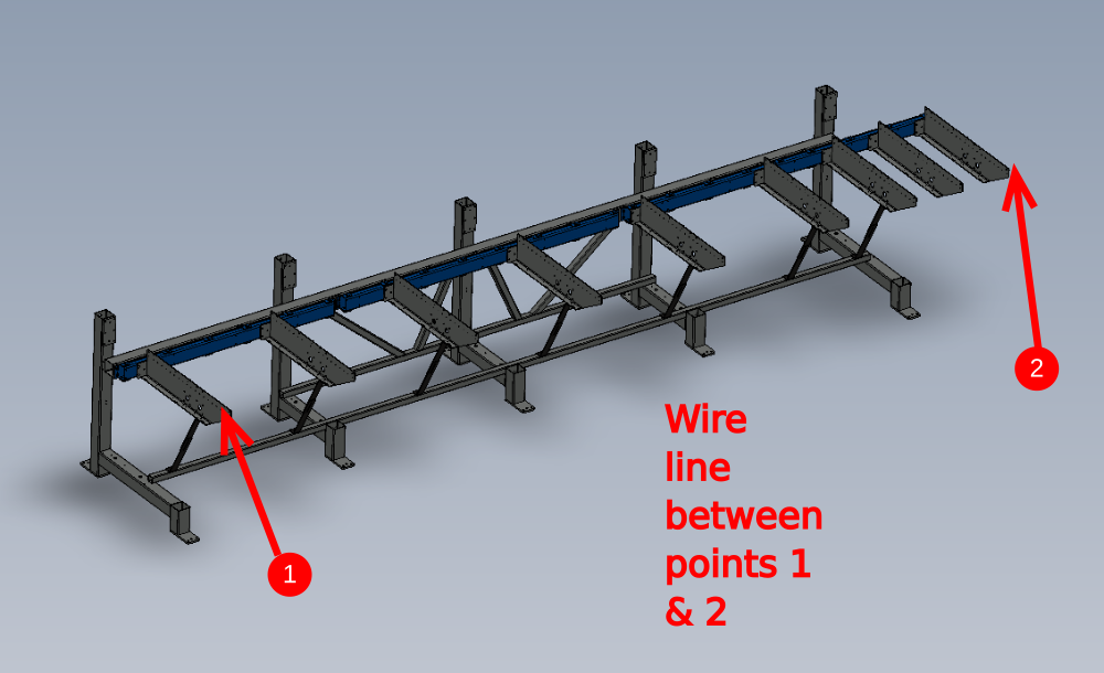
Firstly, identify the two datums that are required to set the wire line to.
A wire line should be pulled tight and then anchored to give a wire line from the first and last component

Étape 2 - Add components
1 Add additional components that require aligning to datum components.

Étape 3 - Adjust components
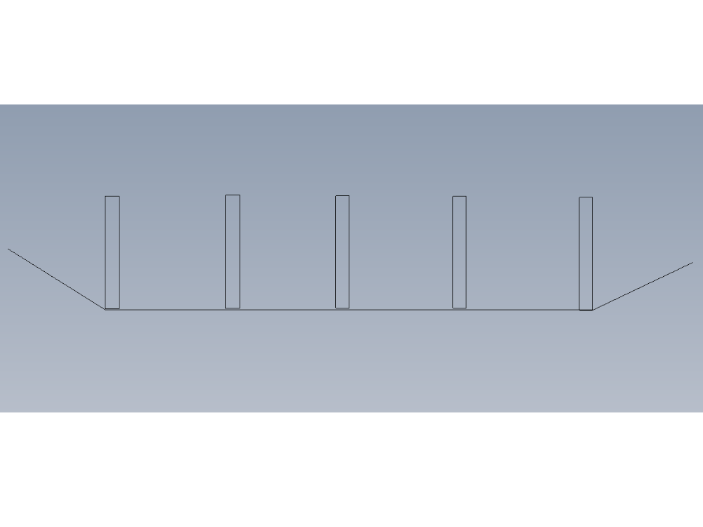
Move non datum components forwards towards the wire line.
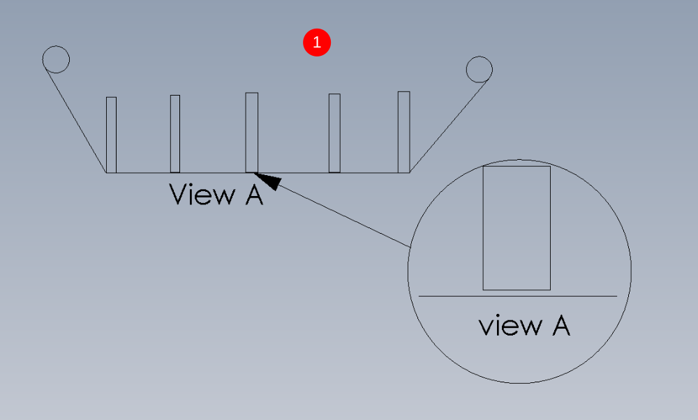
It is imperative that none of these components contact the wire line, as this will give a false reading. The goal is to get the components being added as close to the wire line as possible, without actually physically touching the wire line
this is an example of incorrect use and the exaggerated affect of touching the wire line
Étape 4 - Example of incorrect setting
This is an example of incorrect use and the exaggerated affect of touching the wire line

Étape 5 - Quality check
Once the alignment has been completed, all added parts should be double checked on wire line clearance, to ensure all of the above criteria has been achieved
Draft
 Français
 English
 Deutsch
 Español
 Italiano
 Português