On site upgrade of Flowline Mk3 with Beckhoff AX8000 drives, EtherCAT IO slices and TwinCAT 3 IPC. - Update additional data for a ZX3 or 4


Difficulté
Très difficile
Durée
5 jour(s)
Sommaire
- 1 Introduction
- 2 Étape 1 - Familiarisation
- 3 Étape 2 - Pre-Delivery Checks
- 4 Étape 3 - Pre-Delivery Assembly
- 5 Étape 4 - Parts Identification and Rectification
- 6 Étape 5 - Health and Safety
- 7 Étape 6 - Removal of Components (MH Cabinet)
- 8 Étape 7 - Removal of Components (Saw Console)
- 9 Étape 8 - Removal of Components (Transfer Cabinet)
- 10 Étape 9 - Removal of Components (Motors and Gearboxes)
- 11 Étape 10 - Removal of Components (General)
- 12 Étape 11 - Adding New Components (MH Cabinet)
- 13 Étape 12 - Adding New Components (MH Cabinet) continued.
- 14 Étape 13 - Adding New Components (Saw Console)
- 15 Étape 14 - Adding New Components (Saw Power Panel)
- 16 Étape 15 - Adding New Components (Transfer Cabinet)
- 17 Étape 16 - ZX Machine Y axis Motor to Energy Chain Bracket Interference
- 18 Étape 17 - Adding New Components (Motors and Gearboxes)
- 19 Étape 18 - Adding New Components (General)
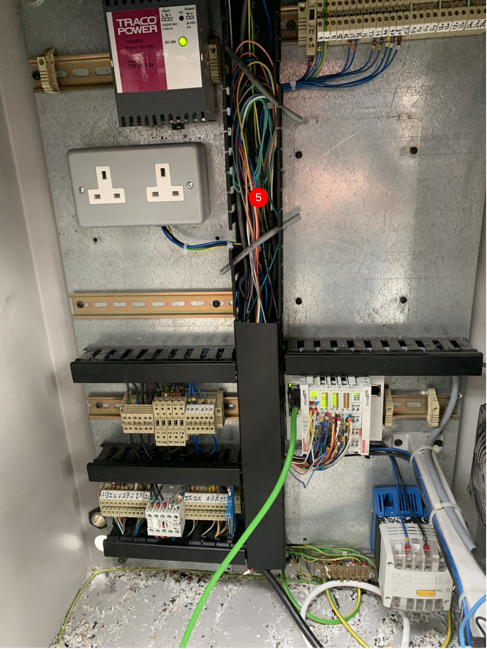
- 20 Étape 19 - Adding New Cabling (EtherCAT and Display)
- 21 Étape 20 - Adding New Cabling (Servo)
- 22 Étape 21 - Adding New Cabling (Servo) continued
- 23 Étape 22 - Adding Offcut Measuring*
- 24 Étape 23 - Fit Yaskawa Inverter
- 25 Étape 24 - IODef Checks
- 26 Étape 25 - Clamps.mul Checks
- 27 Commentaires
Introduction
The Flowline range (Mk3, ZX3, ZX4) are Stuga built and designed machines for prepping and cutting uPVC windows and doors. The Flowline is the first machine of the Stuga 'U' shaped machines which has prepping and cutting working in the same machine package. The Flowline is still a fantastic machine for the industry, however, due to the age of the machines and older control systems becoming obsolescent, we have had to find an upgrade route that does not only keep the machine going, but also provides improvements from the original model and up-to-date technology to future proof the machine.
The upgrade that we have developed for the Flowline is supplied from an automation supplier named Beckhoff. We also use Beckhoff on our new build machines. This gives us better lead times, more understanding of the products and better diagnostics/ support for our customers. The drive system that we use is called the AX8000 series. These drives are a compact multi axis servo system that use an EtherCAT interface and STO safety functions. These servo drives, coupled with Beckhoff AM8*** series OCT servo motors provide quicker installations and all round performance increases from any system we have previously used. To drive all of the new system, we are using a Beckhoff IPC controller that runs TwinCAT 3. This links into the system via EtherCAT. All of the machine can now link together via EtherCAT to provide quick and stable communications.
This tutorial will give you step by step guides on the physical upgrade requirements needed when upgrading a Flowline Mk3 to a Flowline Mk3 with Beckhoff AX8000 Control. Each step will provide you with written information and pictures to guide you through the upgrade. Each step will contain necessary information which will also provide you with rationale for the design and an idea of the benefits over using different methods.
- Fichiers
Attention
Consulter le manuel d'instructions
Porter des lunettes de protection
Utiliser des chaussures de protection
Pour l'entretien, débranchez l'appareil du secteur
Haute Tension
Étape 1 - Familiarisation
The first step does not involve being on site or carrying out any physical tasks. However, trying to gain some familiarisation before carrying out the upgrade can save time and confusion down the line.
Please read through this tutorial before upgrading the machine. The attached files and steps will walk you through the upgrade that somebody else has already experienced. This will give you a free look at any issues or learnings that have already been made.
Étape 2 - Pre-Delivery Checks
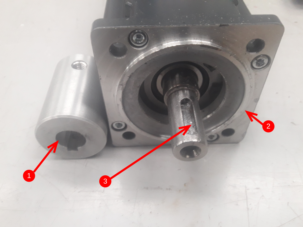
There have been quality issues with bore diameters and concentricity in the past, therefore it is vital to carry out quality checks before the parts are sent to site, as problems and mistakes are very difficult, time consuming and expensive to remedy on-site
- Check bore size of couplings by sliding on the relevant motors
- Check the quantity of motors,
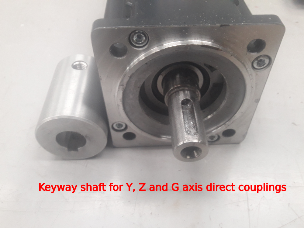
- Check the keywayed motors, it is important that two of the smaller motors are keywayed
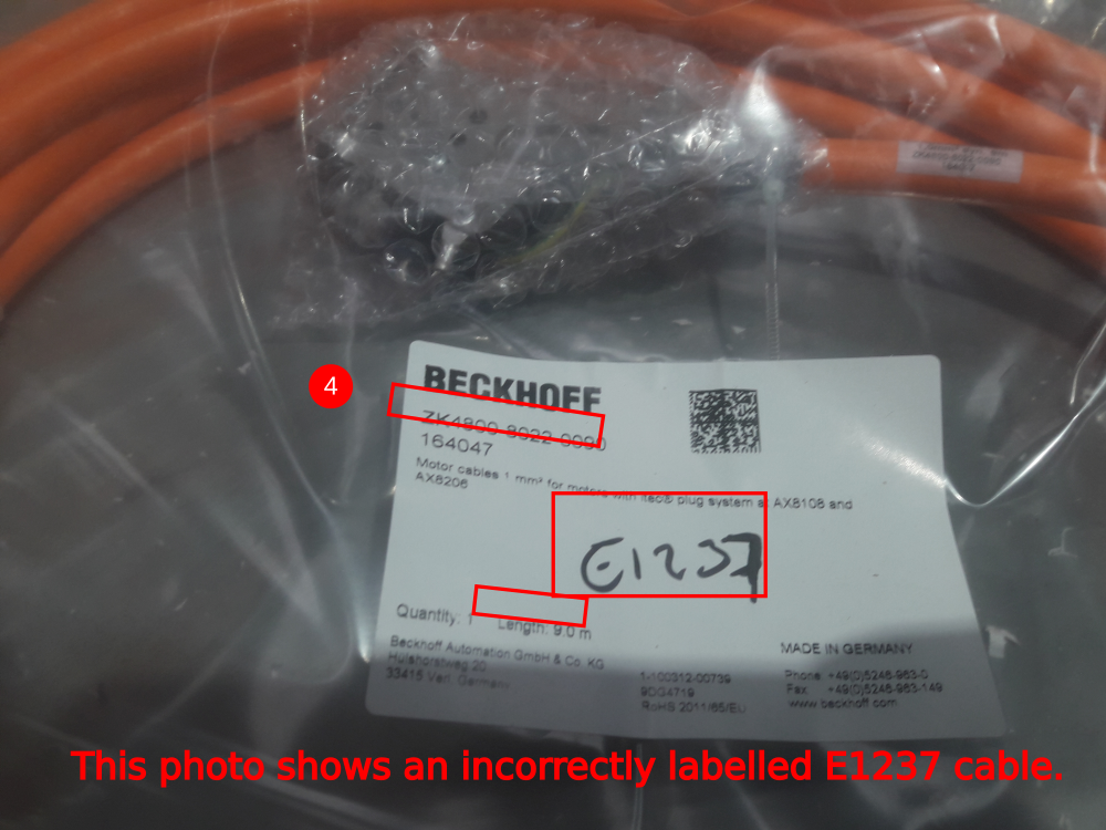
- Check the Beckhoff servo cable lengths carefully - there has been an issue where they have been labelled incorrectly with the Stuga part number
Étape 3 - Pre-Delivery Assembly
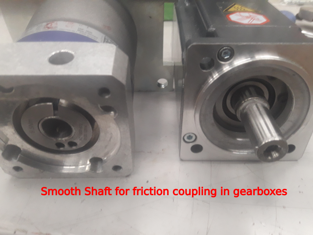
- Assemble the SX, R and X axis motor and gearbox combination. They have a friction fit coupling, so a keyway is not required. Check the friction coupling for the torque setting and ensure it is tightened to this with a torque wrench.
- Note the 10:1 gearbox is for the R axis
- Ensure the keyways, motors and couplings fit together easily for the Y, Z and G axes
Étape 4 - Parts Identification and Rectification
This upgrade is covered by BoM R0010201D. This BoM contains all of the parts necessary to complete the upgrade on the machine. This BoM has been created from previous upgrades and from the knowledge of Stuga engineers.
If any extra parts were identified at the time of ordering, they will appear on a seperate BoM for the specific machine build.
Parts will have been picked and checked at Stuga before despatch. However, the first step when arriving on site is to check that all of the parts have arrived and no parts have been damaged or misplaced. The BoM sheets for the parts will be in the boxes with the parts and should be used to cross reference what has been sent.
If all parts have been cross referenced, move on to step 3. However, if some parts are missing or damaged, please report them to stugaparts@stuga.co.uk and send across the necessary information/ evidence so we can get parts to you. Once this has been sent, move onto step 3.
Étape 5 - Health and Safety
Before any work can be carried out on the machine. You must first ensure that you and the area that you are working in are safe.
Make sure that you ask the customer for their health and safety instructions including first aid and fire safety. Follow all of the health and safety instructions given to you by the customer and Stuga.
Before carrying out any work, ensure the machine is turned off, unplugged and locked off. DO NOT WORK ON LIVE ELECTRICS.
Étape 6 - Removal of Components (MH Cabinet)
List of components to be removed and unwired from the MH cabinet:
- Nextmove E100 - Remove the unit but keep the IO wiring in place as this is where the new IO slices will be wired.
- Nextmove cards (orange IO cards) - Remove the unit but keep the IO wiring in place as this is where the new IO slices will be wired.
- Samsung servo drives - Remove the drives, resistors and wiring.
- Baldor servo drives - Remove the drives, resistors and wiring.
- SA14 unit - Remove the drive and wiring.
- APC - Remove PC, unplug all serial devices, unplug VGA cable and RJ45 cable. The VGA cable will be reused so do not cut this.
- 4 off 10A single pole breakers - There will be 5 breakers in total but we keep 1 breaker in as spare to save time on rewiring the link wires at the top. We will add a 3 pole breaker (10A E0000291) and another single pole breaker further into the upgrade.
- Timer unit - This can be removed completely.
- Ethernet switch - This will be replaced with a newer model.
- Telephone modem - The can be removed completely.
All of the servo and stepper wiring can be removed from the cabinet. The glands that the servo cables enter the cabinet via can also be removed as the new servo cables are bigger.
Étape 7 - Removal of Components (Saw Console)
List of components to be removed and unwired from the Saw console cabinet:
- AcePC - Remove the PC and any wiring that is NOT on a 12 core cable that goes across to the Saw module. The wires that are part of a multicore cable need to be unwired ready for installation into the new IO slices.
- Nextmove ESB - Remove unit and wiring.
- Samsung servo drive - Remove unit and wiring.
- Baldor servo drive - Remove unit and wiring.
- Single pole 10A breaker - Remove wiring and take breaker out.
- Interface relays - All outputs will be +24Vdc switching. If valve bank polarity is incorrect, use an attached TB from Stuga.
- Serial cable for printer - The printer will now run on EtherNET straight from MH cabinet.
The servo drive cables can be removed at this stage. Cut them in half in the Transfer cabinet and pull the remainder through the conduit. These will not be reused. The new Saw Pusher cable terminats in the MH so does not need to be pulled through the conduit.
Étape 8 - Removal of Components (Transfer Cabinet)
List of components to remove from the Transfer cabinet:
- BandR PLC - Remove the unit but keep the wiring for the new IO slices.
- Omron PLC - Remove the unit but keep the wiring for the new IO slices.
- Interface Relays - Interface relays no longer needed so relays that interface 'saw and transfer' and 'transfer and multi' can be removed.
Étape 9 - Removal of Components (Motors and Gearboxes)
List of Motors and Gearboxes to remove:
- X and SX Axis - Remove motors, gearboxes and Gearbox mounting plates (Pinion gears to also be removed).
- R Axis - Remove motor, gearbox and gearbox mounting plate (Pinion gear assembly and belt to also be removed).
- Y and Z Axis - Remove motors, mounting plates and motor couplings.
- G Axis - Remove motor, mounting plate and motor coupling.
Étape 10 - Removal of Components (General)
List of general components to be removed:
- Monitor on MH side - This will be replaced with a touchscreen.
- Monitor on Saw side - This will be replaced with a screen (not touch).
- Keyboard from Saw side - This will be replaced with a bluetooth keyboard.
- Keyboard from MH side - This will be replaced with a keyboard and mouse combination.
- Mouse from MH side - Remove mouse. Will now be integrated into keyboard.
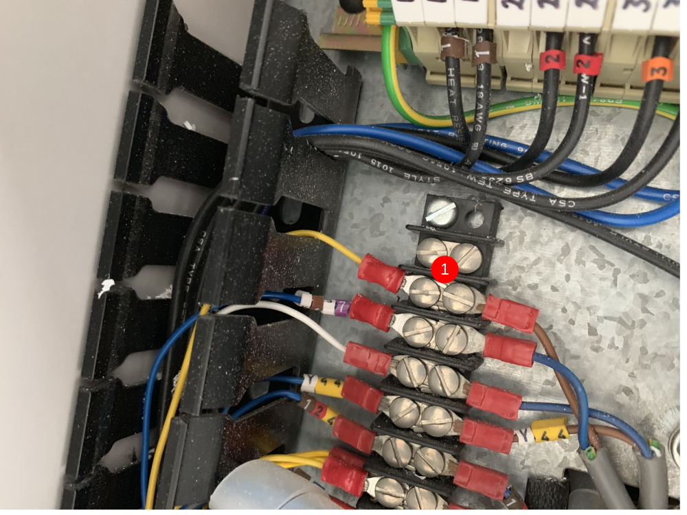
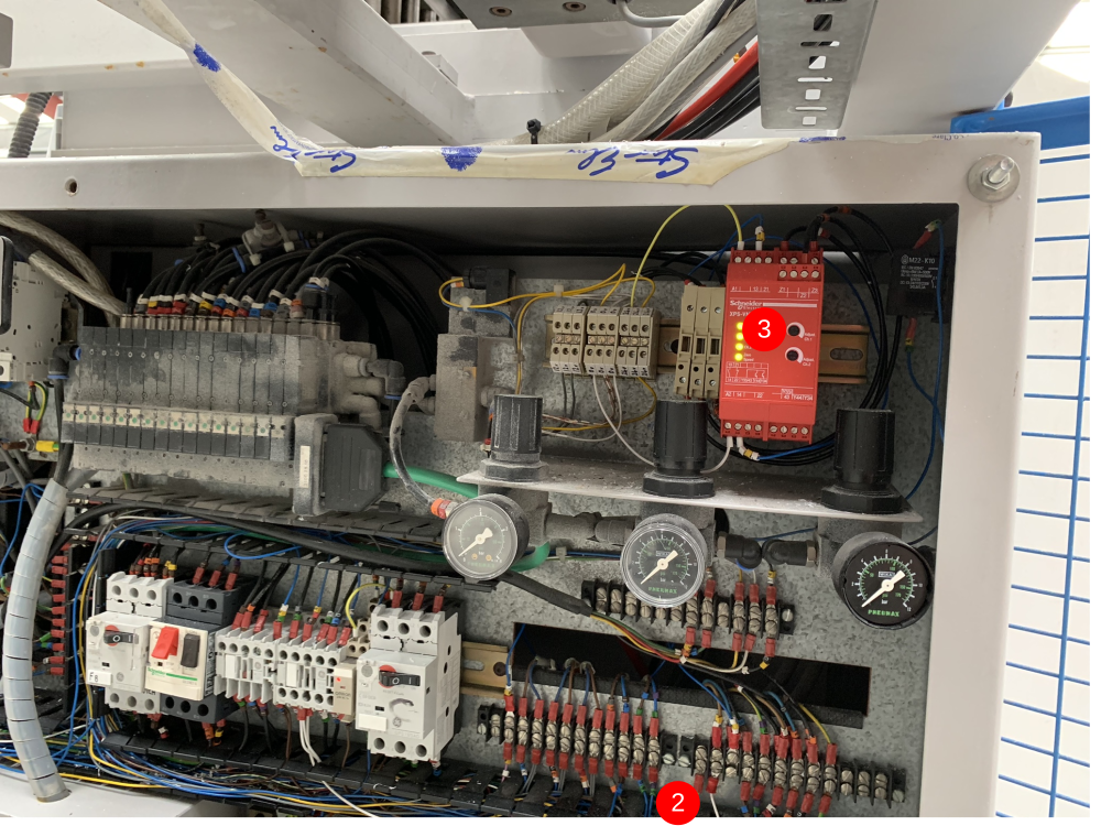
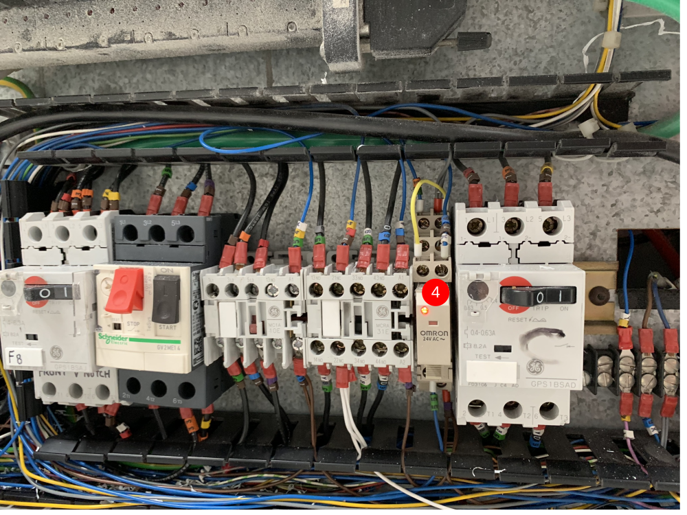
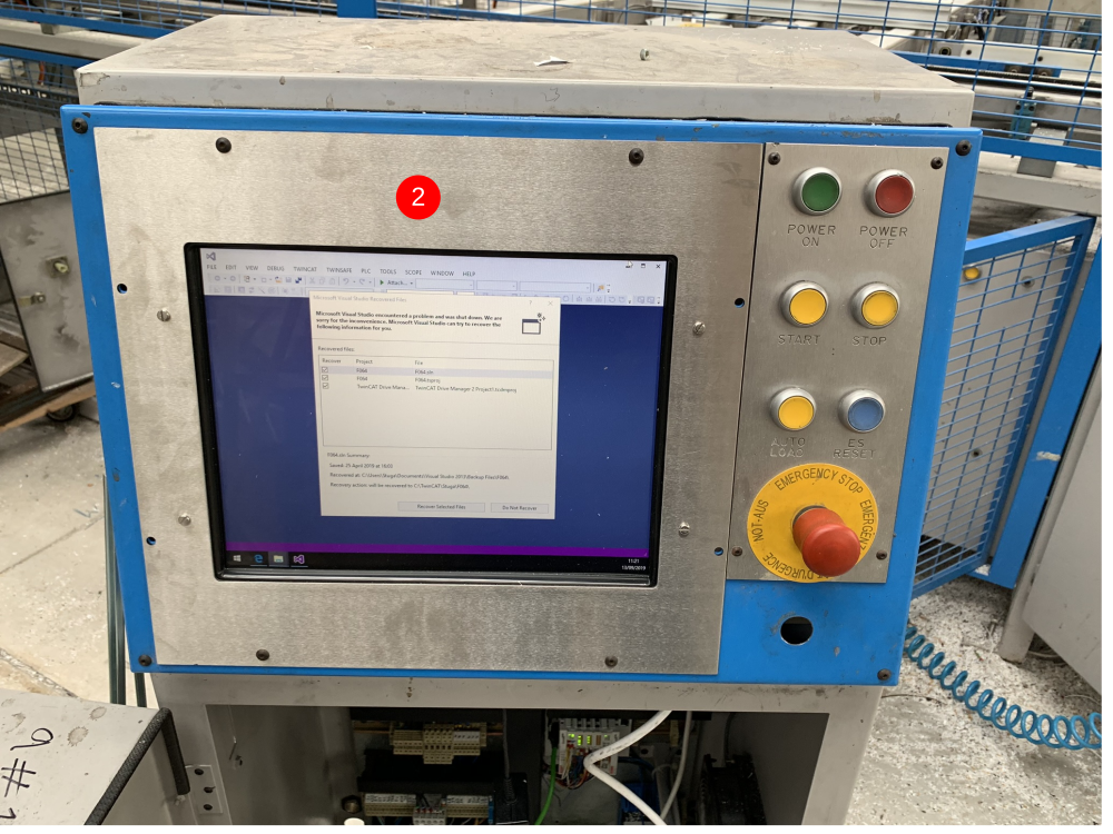
Étape 11 - Adding New Components (MH Cabinet)
List of new components to be added into MH cabinet:
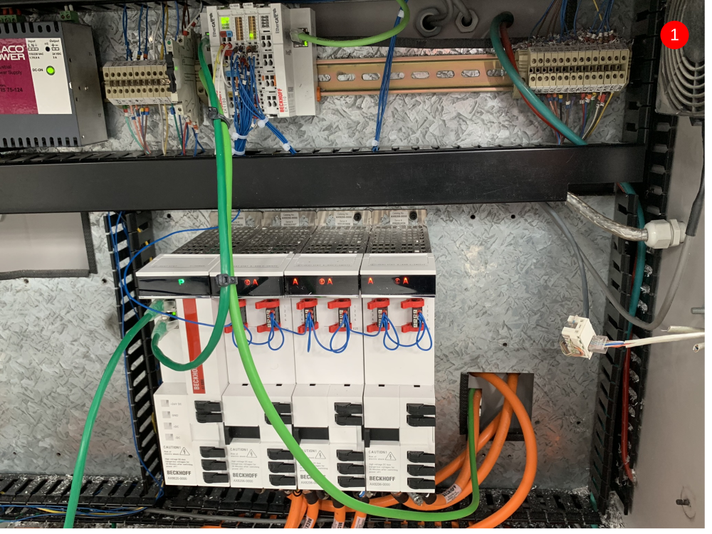
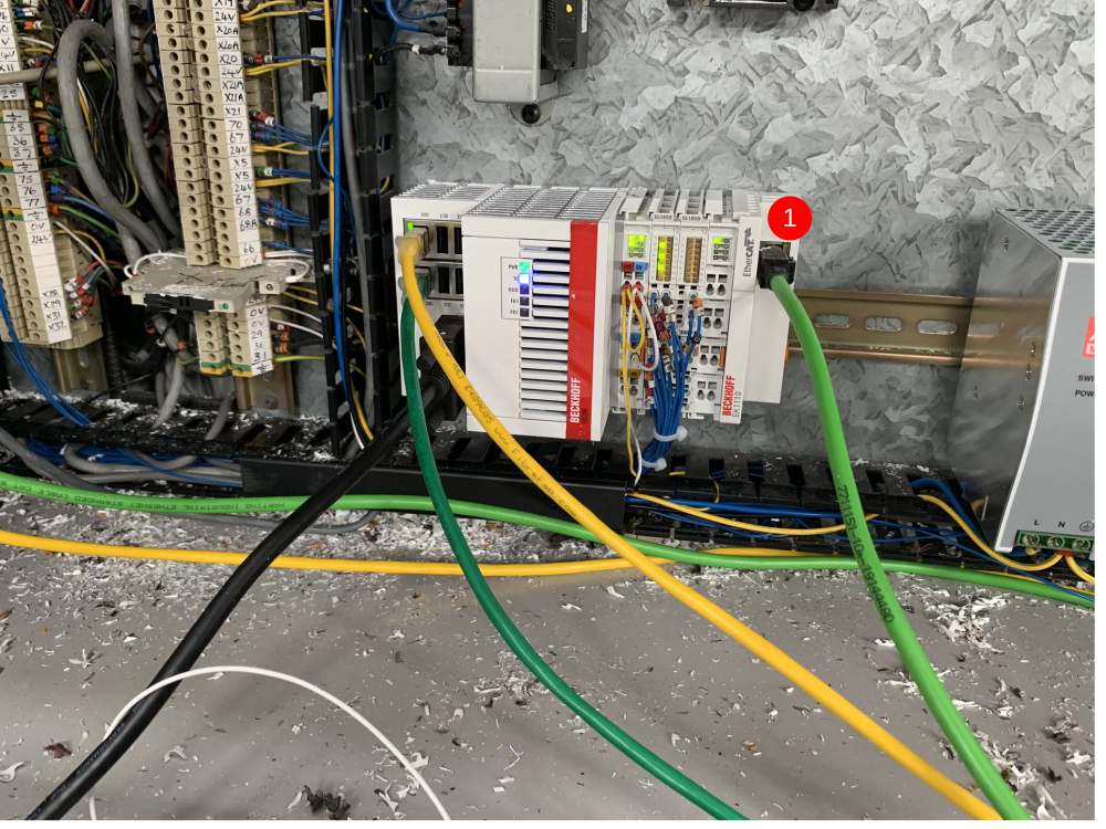
- Beckhoff AX8000 series drives. The drive block (item 1) consist of 4 different devices that all connect together. The first device is the PSU module. It is labelled AX8620. The other 3 devices are all AX8206 drives. These are dual channel servo drives and this is where the motor cables will wire into. Drill the PSU module onto the cabinet back plate and then connect each AX8206 drive individually to each other and drill them off. To connect the drives electrically, you simply push them into each other and slide across the middle connector and pop down the black plastic caps on the previous drive to lock them in place.
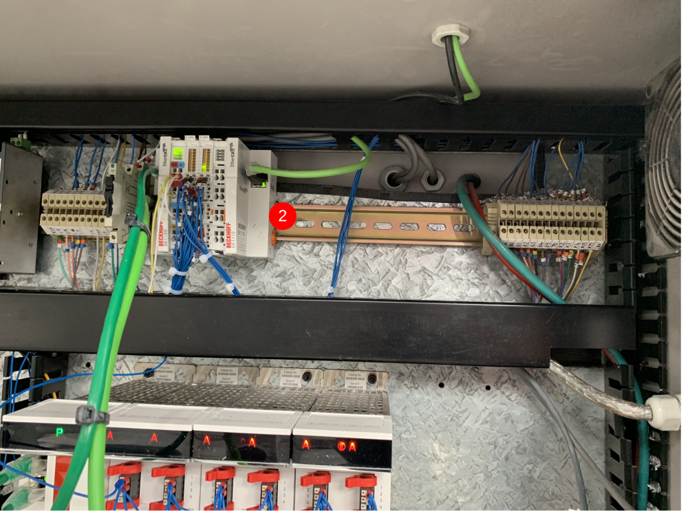
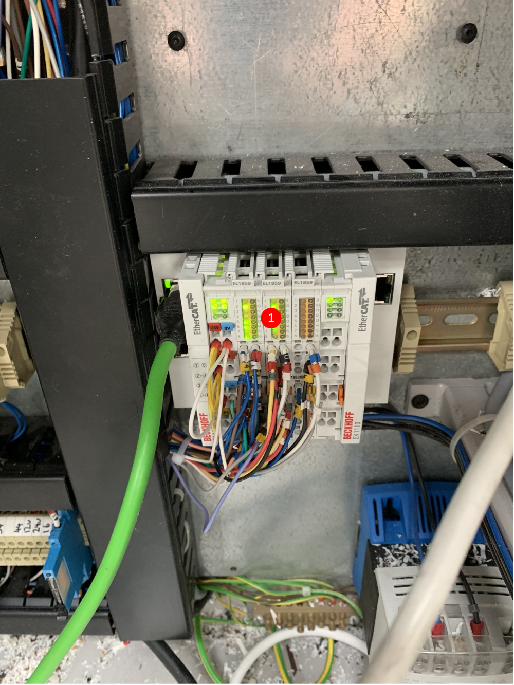
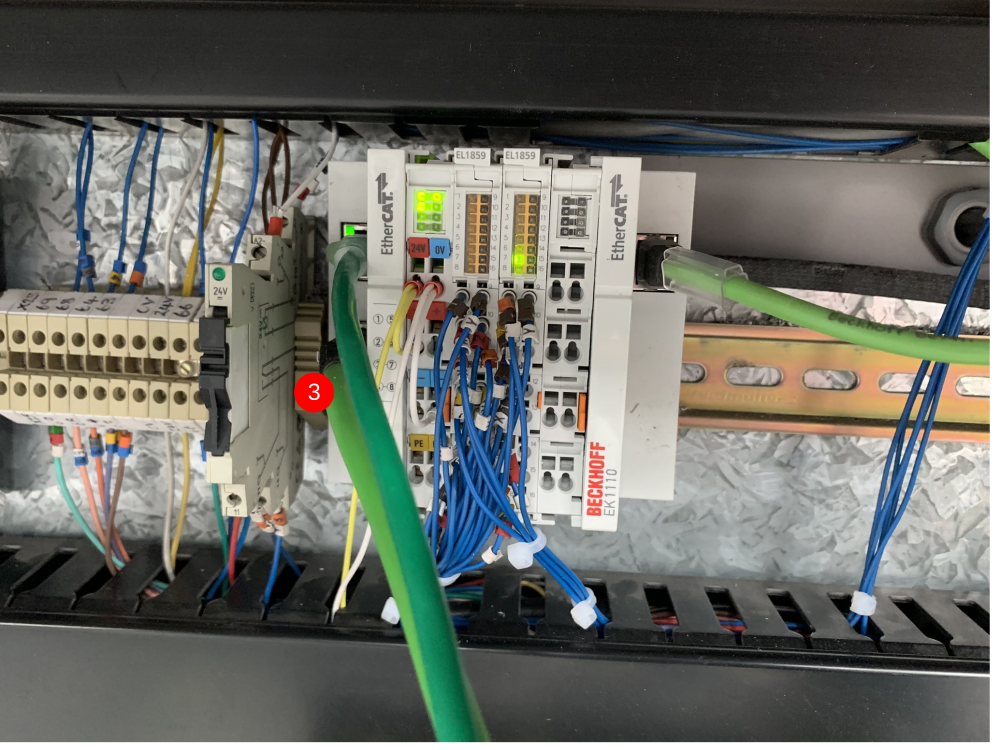
- Beckhoff EK series IO slices (item 2). These IO slices are labelled in the electrical drawings as 'Top Left of Cabinet'. The IO bank consists of 1 off EK1100 bus connector, 2 off EL1859 HDIO slices and 1 off EK1110 bus terminator. This bank of IO replaces all the IO wiring from the old Nextmove controller.
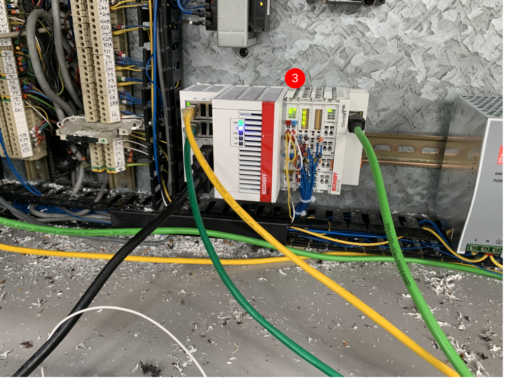
- Beckhoff IPC Machine Controller and IO (item 3). The IPC that controls the machine situates in the bottom left of the cabinet replacing the IO modules from the previous control system. Attached to the IPC is 2 off EL1859 HDIO slices and 1 off EK1110 bus terminator.
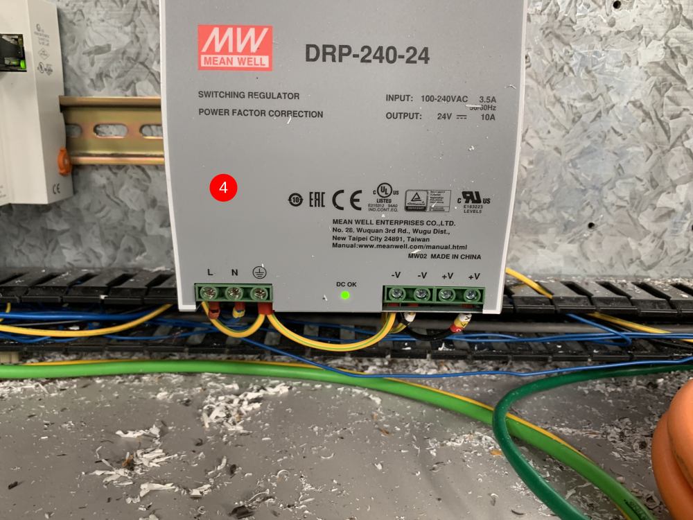
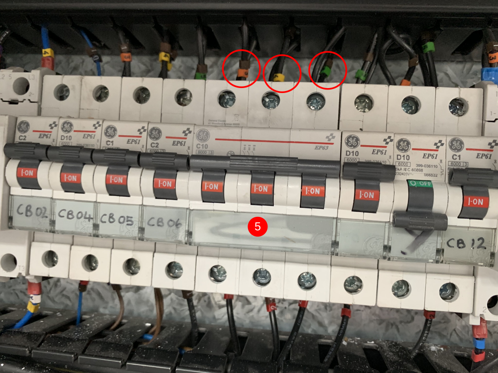
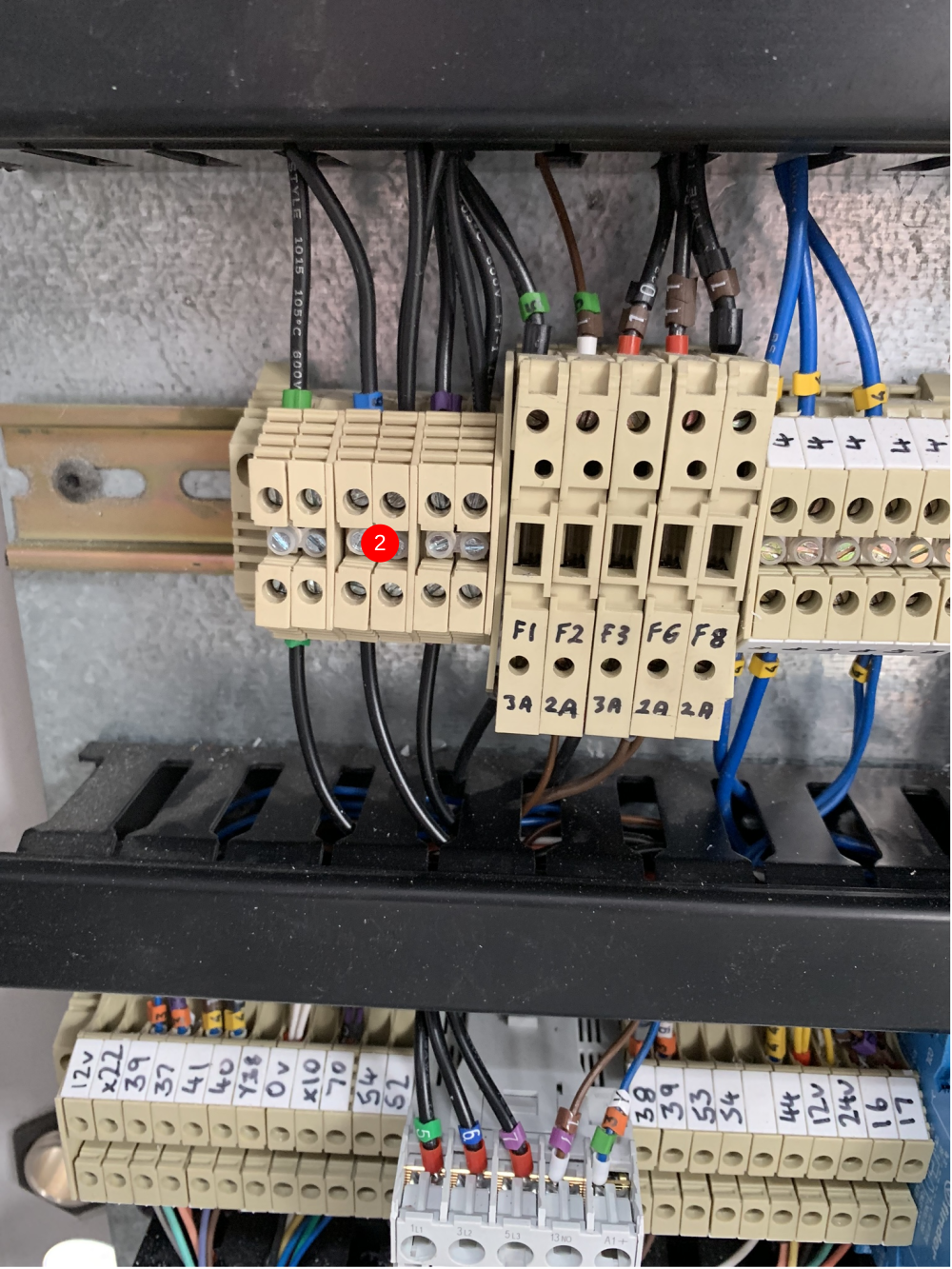
- Additional 24Vdc power supply for the AX8000 drives (item 4). This mounts on the DIN rail next to the 'bottom left' IO and IPC. This then wires into a new 3A 1pole breaker which needs to go in place of one of the breakers removed when the servo drives were removed.
- 10A 3pole breaker for the AX8000 servo drives (item 5). This goes in place of 3 of the old servo single pole breakers. It is important to make sure the wires at the top are 3 individually phases (13,14 and 15).
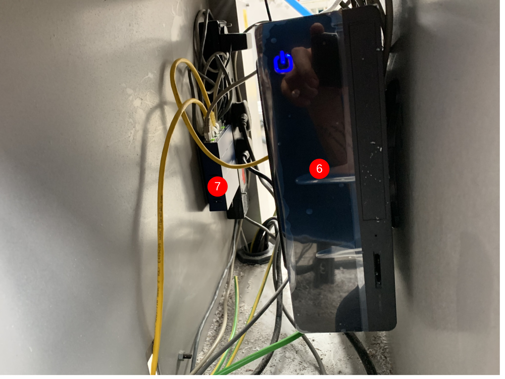
- New front end PC (item 6) needs to be drilled off into the inside of the AcePC enclosure. A new ethernet switch (item 7) needs to be fitted near the PC just using Velcro (this is supplied).
Étape 12 - Adding New Components (MH Cabinet) continued.
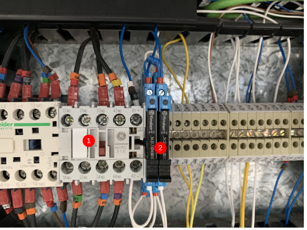
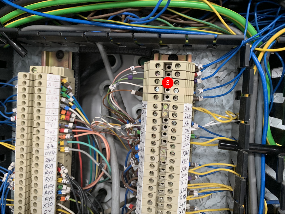
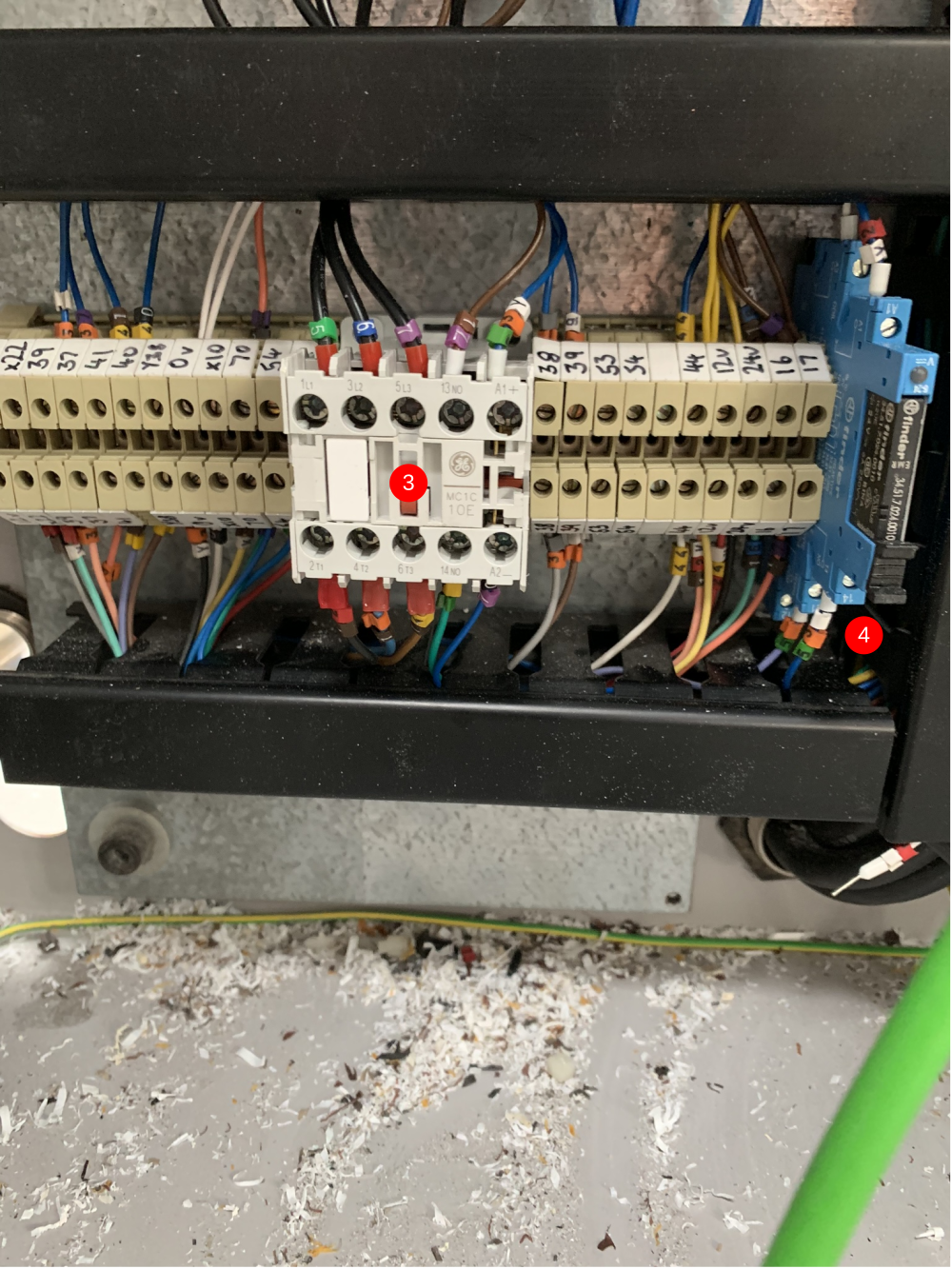
7. 2 24Vdc relays (item 2) need adding for the infeed motor and material load motor control. The 2 relays are activated by 0Vdv (A2) and 66 (A1). The switch side of both of the relays is 0Vdc (11) and Safe_0Vdc (14). The Safe_0Vdc wires go into A2 of the solid state relay and A2 of the new 24Vdc contactor (item 1). 8. The new 24Vdc contactor (item 1) replaces a 24Vac contactor. The original ac contactor had the same wiring in L1,L2,L3,T1,T2 and T3. However the coil was different. Remove the wiring from the old coil. It is no longer needed. Next to the old contactor is a 24Vdc relay which is controlled by Y10. Take the Y10 wire and but this in the new 24Vdc contactor A1. 9. Another new 24Vdc contactor needs adding inline with the 3 phase power for teh AX8000 drives. The contcator can be situated anywhere on the top DIN rail. The 3 wires that come out of the bottom of the 3pole breaker (point 5) need to go to L1,L2 and L3 of the new contactor. New 1mm black wires then need adding from T1,T2 and T3 that go to the AX8000 drives. The A1 of the contactor needs to be 66 and the A2 needs to be 0Vdc. 10. Any relays that are in the cabinet need to be checked for polarity and change where needed. On the old system, the relays were wired so the output from the PLC was in A2 and then A1 was 24Vdc. The outputs have now changed polarity so that the output from the PLC goes into A1 and then A2 is 0Vdc. Tip - if you look on the switch side of the relay and notice that the valve wire (for example) is switching across onto a 24Vdc wire, you can remove the relay completely and just use the output to drive the valve see (item 3).
All wiring details are in the electrical drawings for the machine. These can be found in the documents at the top of this page.
Étape 13 - Adding New Components (Saw Console)
- Beckhoff IO Slices need to be fitted (item 1). Where they are mounted in the cabinet is governed by the length of all of the 12 core cables that go across to the saw. The 12 core cables carry most of the IO that needs to be terminated in the slices. The other IO comes from the buttons and the Transfer cabinet 12 core.
- The 24Vac contactor that controls the On/Off circuit in the Saw is no longer required. The easiest way to remove this is to link L1 with T1 L2 with T2 and L3 with T3 using terminals. The other wires that were in the contactor can be removed. This means that the buttons will no longer have a function.
- Changing the Saw Motor contactor to 24Vdc. Remove the 24Vac contactor. The 3 phase wires can be directly replaced into the 24Vdc contactor. The A1 for the new 24Vdc contactor needs to be 70. 70 is a 0Vdc switched wire through the ES relay that means the contactor will be deenergized under Estop. The A1 of the contactor needs come from terminal 14 on the Y2 relay (item 4).
- The Y2 relay needs a light wiring change. First the Y2 wire needs to be in A1 and a 0Vdc wire in A2. On the switch side of the relay, wire number 53 needs to be in 11 and 53A needs to be in 14. Wire 53 is on a 12 core that oes across to the saw. It is energised when the guard circuit is healthy. This wiring change means that you no longer have to press the start button to latch in the Saw Motor contactor. This is required for the new programming logic.
- The Saw console cabinet has a lot of spare space (item 5) but that is because the PC and Drives are now being handles on the MH side.
Étape 14 - Adding New Components (Saw Power Panel)
- Wire X2 is no longer required for Beckhoff machine. This now means we can use it for something else. One of the inputs that the Beckhoff software does require is to say whether the blade is at 45deg or 135deg. This where the X2 wire comes in. There will be 2 cables that terminate into X14, these need to be seperated. One of the cables remains in X14 as this now becomes the Saw @ 45 input. The other cable needs to be moved and wired into X2 (renumbered to X197) this is now the Saw @ 135 input (item 1)
- The guard circuit requires a slight rewire to match the changes we made in the Saw console cabinet. The start of the guard circuit is the Atlas 5. The wiring for the Atlas 5 (item 2) starts as 16 and 57 (n/c switch) Y4 and 24Vdc (guard solenoid). The 24Vdc wire needs removing completely. The Y4 wire needs to be moved across so that it is not connected to anything yet (it will go to the zero speed). A 0Vdc wire needs to go where the Y4 wire was and a new wire labelled Y4A needs adding to where the 24Vdc wire was. This wire will then go to the Zero Speed detector (item 3). The original Y4 wire goes into terminal 13 on the zerop speed detector. The new Y4a wire goes into 14. The zero speed also needs a 24Vdc wire in A1 and a 0Vdc wire in A2. The zero speed detector works by monitoring the saw blade phases. To do this, attach 3 1mm black wires to the saw blade U,V and W phases and wire these into 3 fuse blocks (next to zero speed in picture) These fuse blocks need to have 500mA fuses fitted. Then add 3 1mm black wires from the bottom of the fuses to the zero speed. U goes to Z1, V goes to Z2 and W goes to Z3.
- The relay that is activated when all the guards are closed needs a slight change (item 4). The switches on the top are 24Vdc and X16 (PLC input) and 17 and 53 (Saw Motor Safety Connection). Wire number 17 needs to be removed and replaced with a 24Vdc wire (item 4). This is what eventually pulls in the Saw Motor contactor and this has been changed to 24Vdc.
- The HiLo pressure valve needs polarity changing. This is simple, the 24Vdc wire just needs to be changed to a 0Vdc wire.
Étape 15 - Adding New Components (Transfer Cabinet)
- Beckhoff IO slices go in place of the Omron or B&R PLC that was originally fitted. This needs to be situated so that the old IO wires will reach.
- The transfer On/Off button is now required to be in an input rather than a power switch for the PLC. The button needs to have 24Vdc supplied to it and on the switch side of the contact it needs to go into the IO slices. The IO slices need to have 24Vdc and 0Vdc to power them.
- As with the MH panel. The relays that are fitted need to be checked for polarity. The output should be A1 and A2 should be 0Vdc. In the case in the picture (item 2) the valves were activated by a 24Vdc signal and that allowed me to remove the relays and fire the valve straight from the output.
- The solid state relay needs to be switched off under Estop. To do this, use wire 24 (same as 70 in the saw) in A2.
![]()
![]()
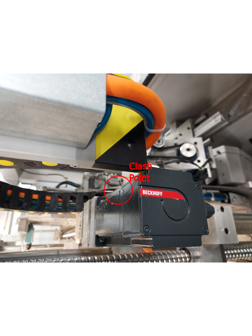
Étape 16 - ZX Machine Y axis Motor to Energy Chain Bracket Interference
On ZX3 and ZX4 machines, the Y axis energy chain bracket needs to be modified to allow the Y axis motor additional space.
An 8mm x 120mm section needs to be removed with an angle grinder and CUTTING disk.
- Remove the trunking lids
- Remove the securing screws from the rear of the welded bracket that secure the silver Y axis energy chain mounting bracket , tie the bracket, energy chain, etc. away from the area you are about to cut away.
- Take the airlines and cables from the small vertical, the 90 Degree bend and Horizontal Trunking sections and tie them out of the way (towards the infeed table)
- Remove the short vertical piece and the 90 Degree bend sections of the trunking completely including the securing screws
- Carefully remove the Black / Yellow warning tape and put it aside as you will need to refit this later
- Cover the area to protect it from metal sparks as these will be considerable
- Mark out a section 8mm x 120mm as per the photograph to allow the motor to pass the bracket without fouling it
- Using the correct PPE, cut away the marked out section as per the Photograph
- A metal file will be needed to remove any sharp burr's left behind during the cutting process. Ensure that there are no sharp edges left behind as this area is often a collision zone by Personnel when carrying out Maintenance on the machine
- Refit all the the removed parts in reverse order
- Check the full movement of the Z axis to ensure that you have removed enough material to allow the Y axis motor to pass the bracket unhindered
- Refit the Black / Yellow waring tape to the bracket again


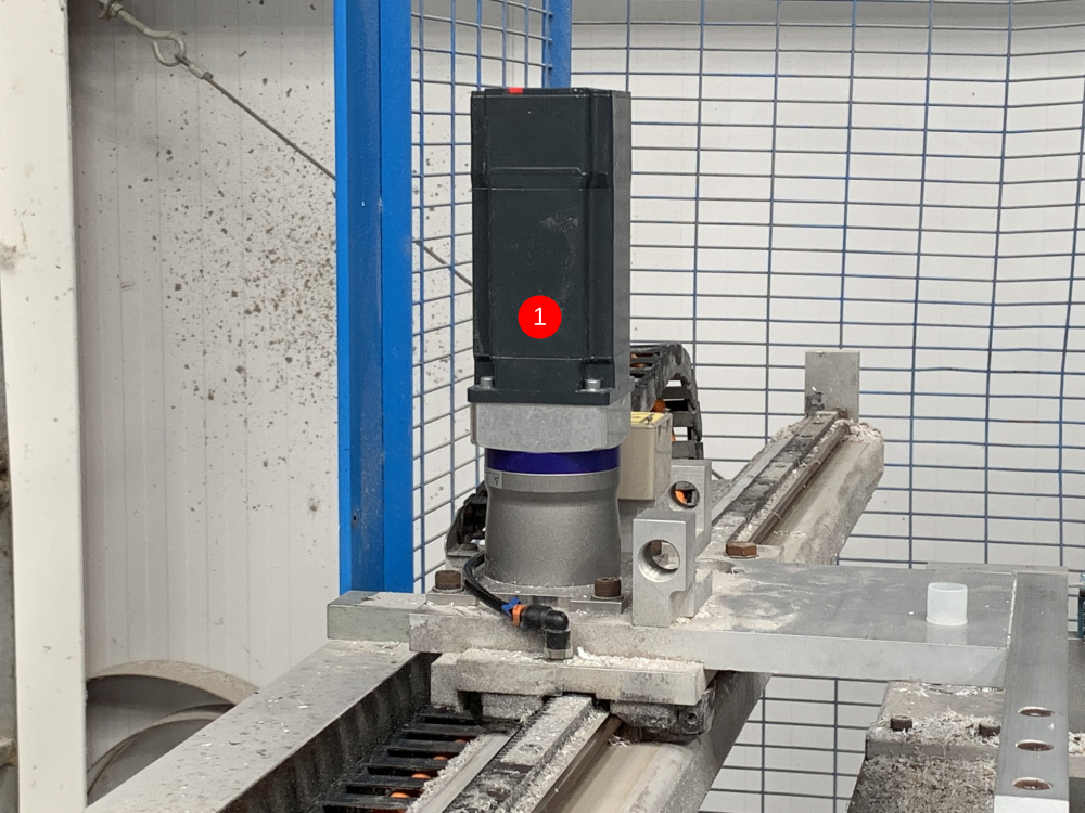
Étape 17 - Adding New Components (Motors and Gearboxes)
- X and SX Axis - Fit gearboxes to supplied mounting plates, The motors then fit onto the gearbox assemblies. New Pinion gears needs to be set at correct height on gearbox shafts so they dont bottom out on the hepco rails (Gears shouldn't fit tightly onto gearbox shafts - ideally a 'location fit' should be observed). Now Fit entire assembly onto carriages, meshing the pinions fully into the hepco rails (Item 1).
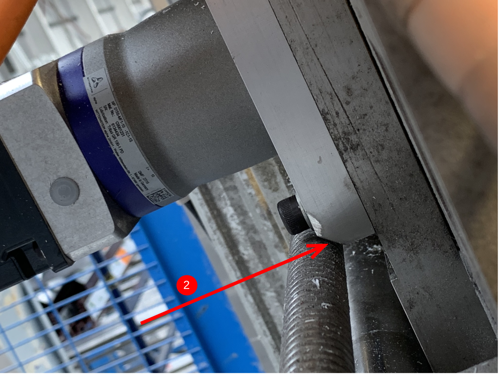
- R Axis - Fit Motor to Gearbox. Fit Pinion gear assembly to gearbox and adjust tension to belt (make sure belt runs parrallel between both pulleys). Fit assembly onto R axis, meshing pinion fully to hepco ring. (Clean /blow out hepco ring before new assembly is fitted). Note: Make sure bottom of mounting plate is clear of Y Axis leadscrew (Item 2).
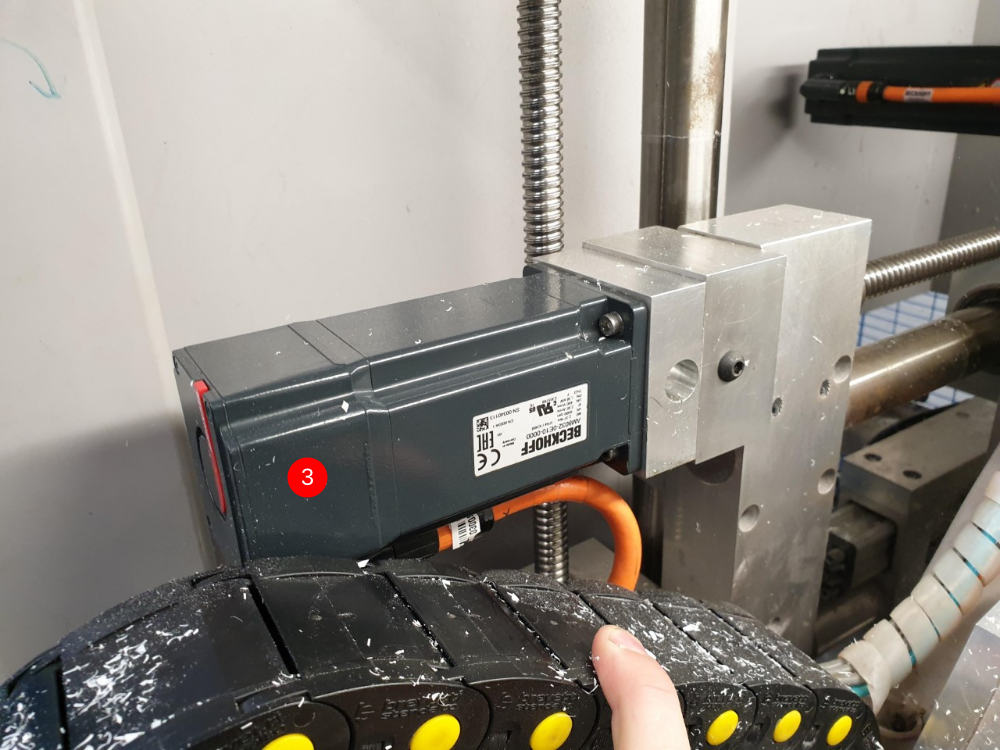
- Y and Z Axis - Fit mounting plates to leadscrew plates. Fit leadscrew couplings to motor shafts (Make sure the coupling are not tight on shafts - ideally a 'location fit'). Now fit motor assembly to mounting plate. (Item 3). Remember to tighten grubscrews on couplings.
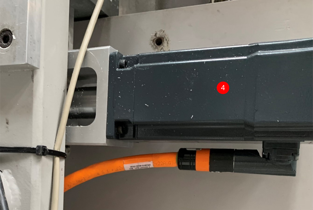
- G Axis - Fit mounting bracket to outfeed frame first. Fit leadscrew coupling to motor (Make sure the coupling are not tight on shafts - ideally a 'location fit'). Now fit motor to mounting bracket. (Item 4). Remember to tighten grubscrews on coupling.
Note - After each assembly is complete, manually check all axis movements.
Étape 18 - Adding New Components (General)
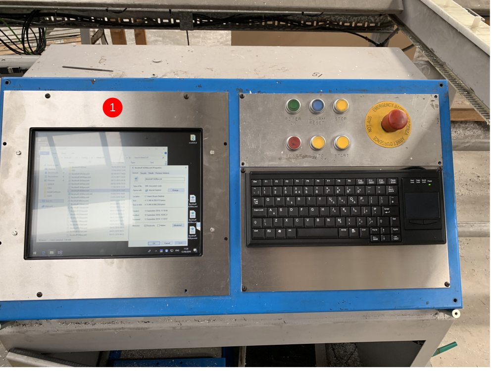
In the kit of parts, you will get 2 touchscreen bezels. 1 of these is for the MH side and 1 is for the Saw Console. The MH side also receives a keyboard bezel. MH side is item 1. Saw side is item 2.
Both monitors need power and display. The MH side has a terminal rail in the bottom that has LNE terminals. The PSU for the tocuhscreen is seperate. This needs to be found in the kit. One end of the PSU plugs into the back of the touchscreen , the other end has a plug for the wall on but this needs to be cut off and then terminated into LNE on the bottom termanil rail. The touchscreen also receives the original VGA cable. There is a USB cable that comes with the touchscreen which needs connecting. The keyboard also needs fitting. This will leave you with 2 USB2.0 cables that need connecting and these will be attached to a 5m USB extension cable that runs back to the MH side front end PC (items 3 and 4).
The old Saw side monitor had a kettle lead already terminated. This can plug into the PSU for the touchscreen. There will be a HDMI cable that runs from the MH front end PC to the Saw console which goes into the monitor. See; 'Adding New Cabling (EtherCAT and Display)' for more detail. There will also be a bluetooth keyboard in the kit which is for the Saw side. The dongle that comes with the keyboard needs to be plugged into the front end PC.

Étape 19 - Adding New Cabling (EtherCAT and Display)
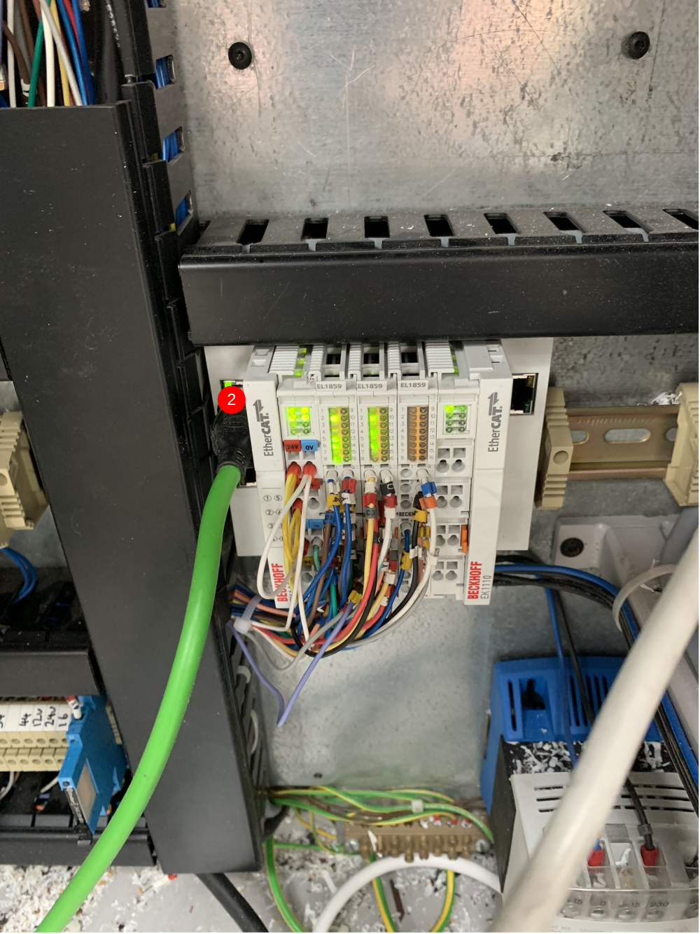
- A new 32mm conduit needs to be cut and made for the connections between the Saw console and the MH cabinet. The conduit needs to be 7.5m long and have the 15m HDMI cable and 1off 10m Green RJ45 cables going through it. The HDMI cable plugs into the front end PC on the MH side and the Saw monitor in the Saw console cabinet. The 10m Green RJ45 cable goes into the EK1110 slice at the bottom left of the MH cabinet (item 1). The othe end goes into the top port of the EK1100 in the Saw console cabinet (item 2).
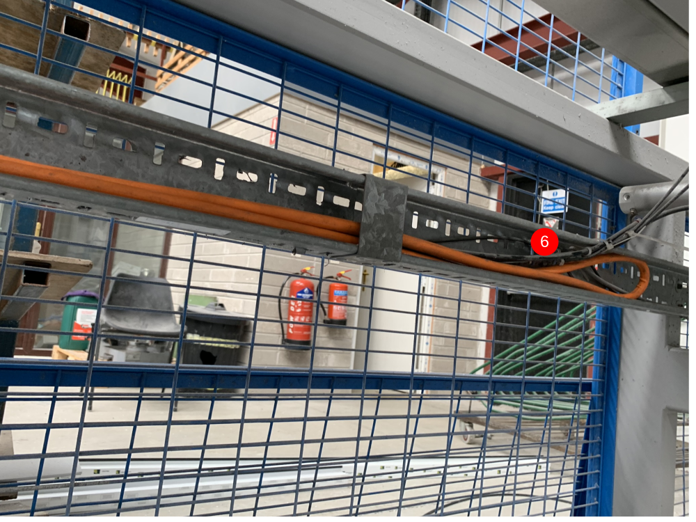
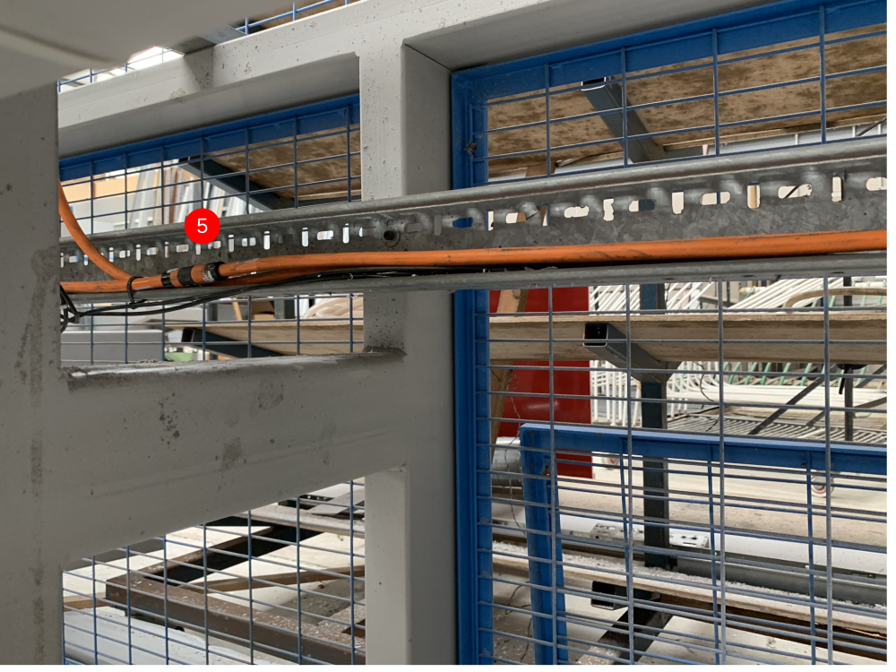
- The EtherCAT cable for the transfer IO comes from the bottom port of the EK1100 in the top right of the MH cabinet. The cable leaves the cabinet through the old X axis slot and runs around the frame with the servo cables (item 4). It then goes onto the MH outfeed cable tray and up with the SX servo cable and through the transfer beam (the one the already has cables going through (item 5). It then drops out of the beam and into the transfer cabinet EK1100 top port (item (6).
- The MH ethernet switch is where the printer needs to connect. To do this, another anaconda needs making up at 7.5m. You need to put 1off 10m Yellow RJ45 cable through. The MH end terminates in the ethernet switch. The other end plugs into the printer.
The anacondas need to be layed so that they are on the inside of the machine and not laying on the floor between the MH and Conveyor.
![]()
![]()
Étape 20 - Adding New Cabling (Servo)
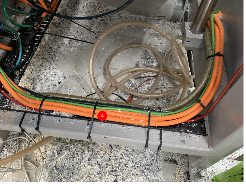
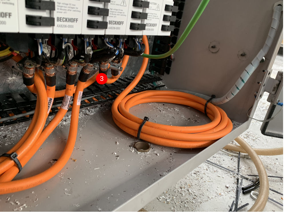
- All of the servo cables for the machine terminate in the MH cabinet AX8000 drives. The cables that are supplied have plugs on both end. This means that the motor end plug has to fed through the inside of the cabinet to go to the motor. The G, X and SX axes cables come out of the inside of the cabinet and the go around the rear of machine and out onto the MH outfeed table (item 1 and 2). These 3 cables need to be pulled all the way through the cabinet so there is no slack left (item 3). The G axis comes out of the rear of the MH and plugs straight into the motor. The SX axis runs across the MH outfeed cable tray and then through the transfer beam (item 4). The X and SX axes have an extension cable. The extension cables have a normal motor end plug but they also have a male version of the motor connection plug. The XExt and SXExt cables need to be run through their individual energy chains and plugged into the motor. The cable that comes from the MH cabinet then plugs into the Extension cable. The slack is then lost in the cable trays (item 5 and 6).

![]()
Étape 21 - Adding New Cabling (Servo) continued
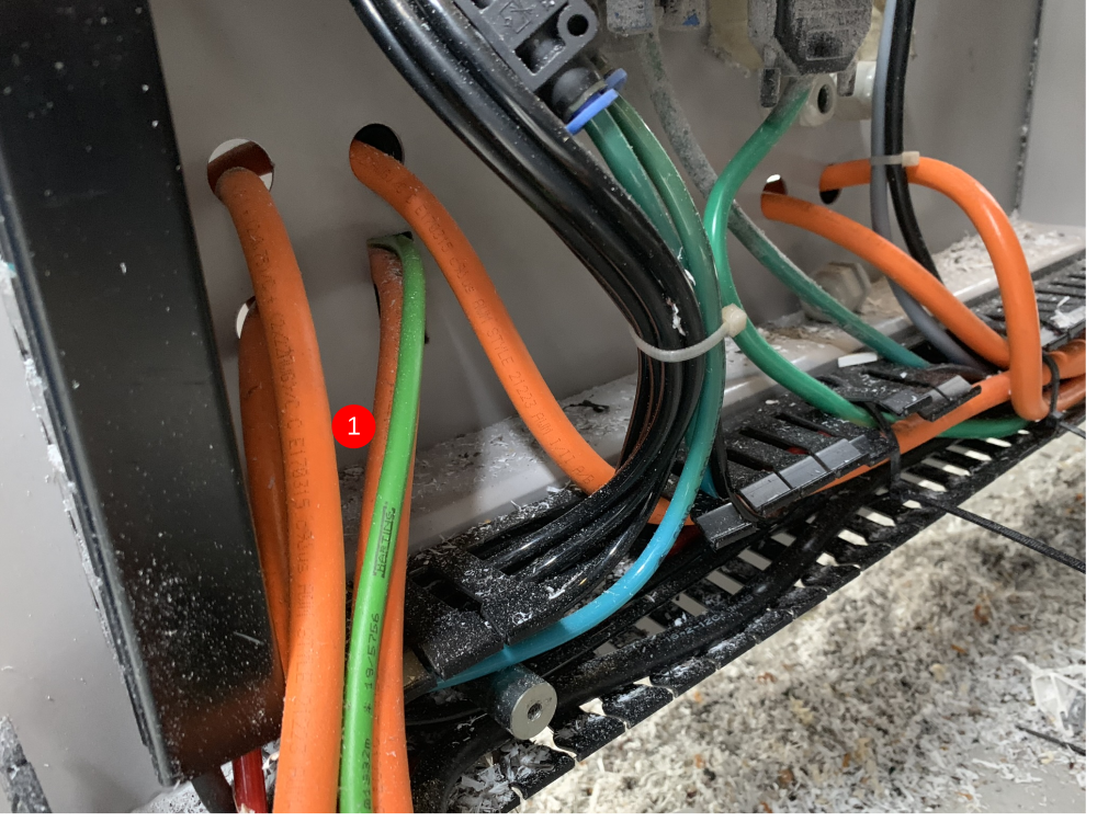
The Y,Z and R servos come out of the back of the cabinet and run in the same way the did previously. The difference with the Y,Z and R is that the slack on the cables needs to be inside the cabinet. This means you have to run the cable to the motor and then tidy it up in the trunking when you bring the slack back to the cabinet.


Étape 22 - Adding Offcut Measuring*
**This is only for machines that do not have the Autoqueue sensors fitted**
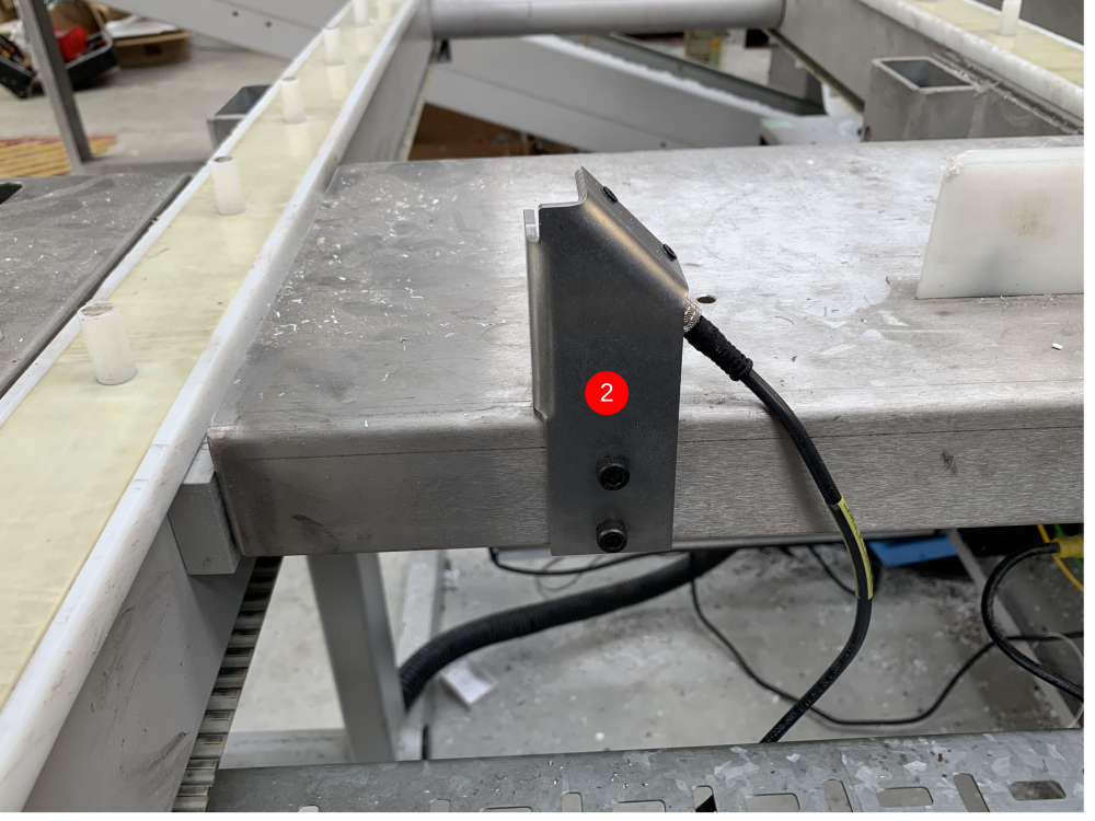
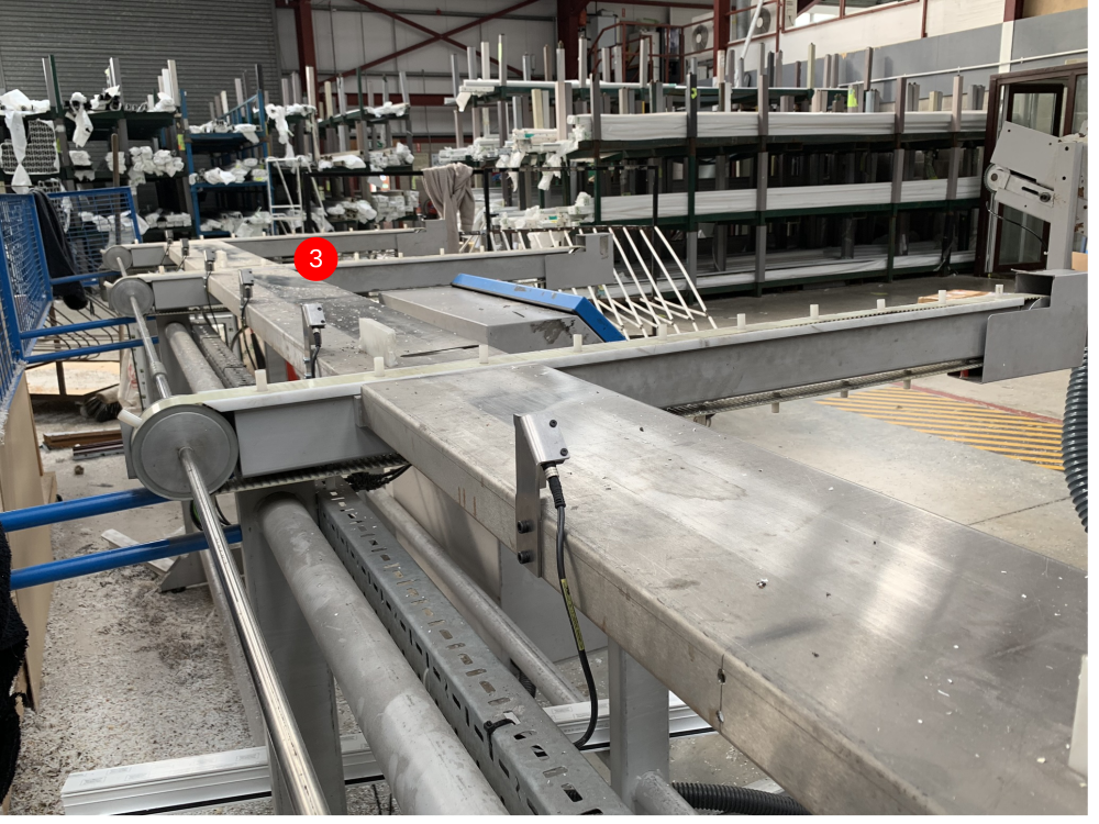
- You will find an EtherCAT box and mounting plate in the kit. There is also a 5m EtherCAT and Power cable. The box needs to be mounted 3.5m down the infeed frame (item 1).
- The sensors are mounted the same as they have always been. The measurements for where to mount the sensors is on R0000280 (attached). The sensor will look like item 2 when fitted and item 3 is a look down a frame with all sensors fitted.
- Each sensor has a m8 4pin 5m sensor cable. These are long enough to work on all the sensors. All of the sensors wire back to the EtherCAT box. The sensor closest to the MH goes into port 0 and then follows sequentially. To terminate the cable, you will need to fit m8 3pin plugs. The cables are 4 pin so you need to cut out the white wire. You then wire the cable and plug colour to colour.
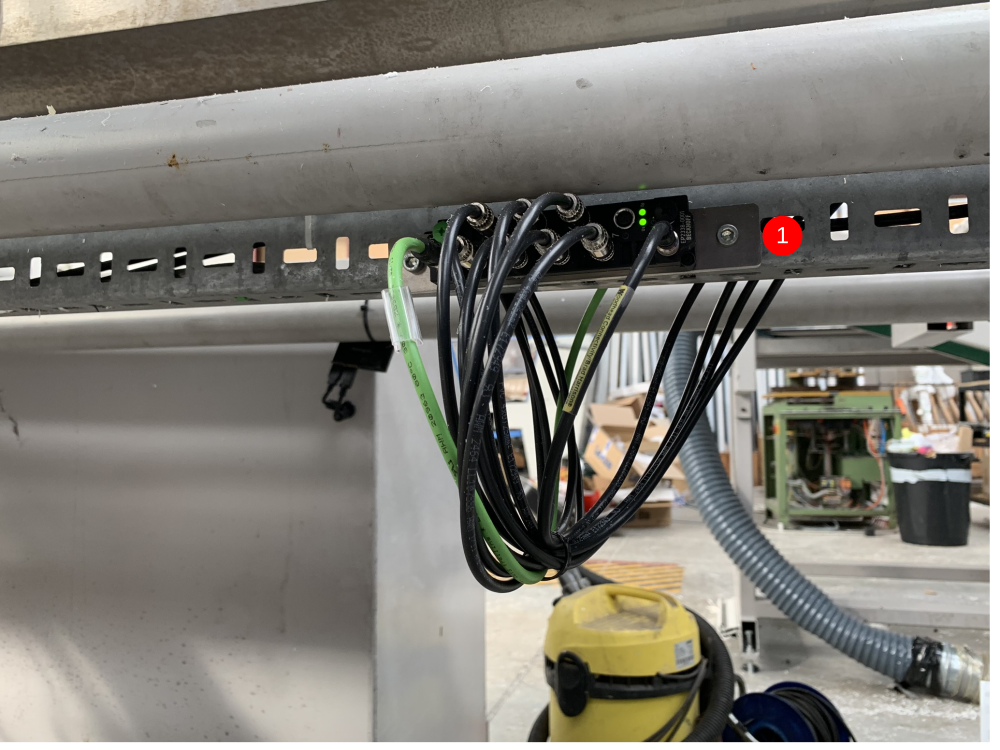
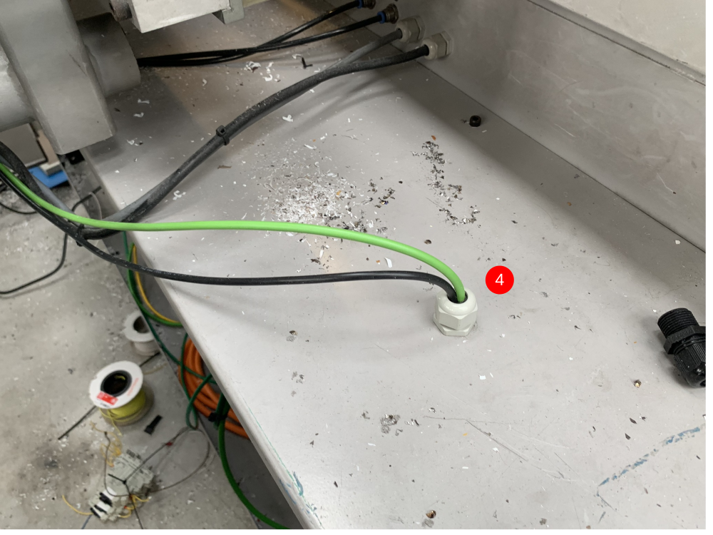
- The 5m EtherCAT cable then needs plugging into the In port (this port is green too) and the power cable is another m8 4pin 5m cable that plugs into the female port. These then run back to the MH cabinet. A gland is needed and the cables go into the top of the cabinet (item 4).
- When the cables are in the cabinet, the EtherCAT cable plugs into the EK1110 on the top right of the cabinet. The power cable needs to be stripped back and Brown + White go into 24Vdc and Blue + Black go into 0Vdc.
Étape 23 - Fit Yaskawa Inverter
Étape 24 - IODef Checks
The IODef file may need updating for the system
SMOT output needs to be IORef number 62
Étape 25 - Clamps.mul Checks
The Z support output needs to be inserted in clamps.mul file
Draft
 Français
 English
 Deutsch
 Español
 Italiano
 Português