Upgrade parts and procedure to replace obsolete load roller motor B0000082

Difficulté
Moyen
Durée
2 heure(s)
Introduction
To rectify the obsoletion of B0000082 drive motor, the following replacement kit has been designed to enable continued support of older assemblies within stuga machines .
The kit consists of a new motor and appropriate gearbox, adapter plate and new fasteners . Also details are included here for a small modification to enable the upgrade to function correctly
Following parts are required for this upgrade
B0000082b load motor and gearbox 1 off
D0008225b adapter plate
F0000189 M6 x 25 set bolts 4 off
F0000058 A form washer 4 off
F0000190 M8 x 40 set bolts 2 off
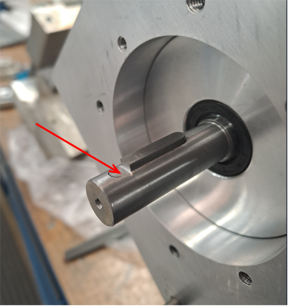
F0000007 M5 x 16 cap head bolt 4 offÉtape 1 - Motor drive key Modification
New motor B0000082b will need modification of drive key to function correctly.
5mm should be removed from key in situ as shown in photo
This will enable clutch plate to move to desired position on assembly
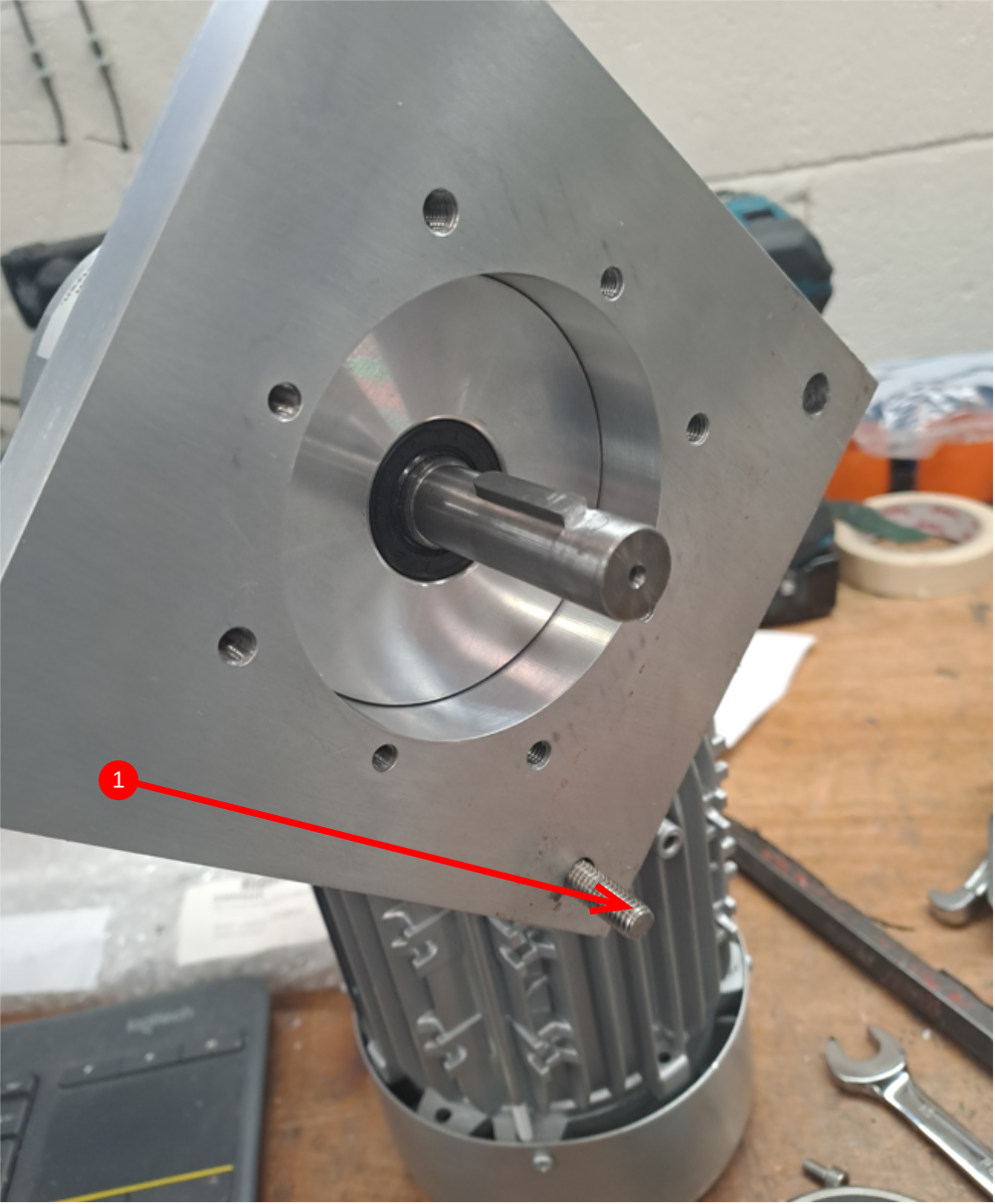
Étape 2 - Fit D0008225b adapter plate
1
2 Using 4 off m6 x 25 set bolts and A form washers , adapter plate should be mounted to Booooo82b motor in configuration as shown. Loctite 243 Adhesive should be applied to fasteners
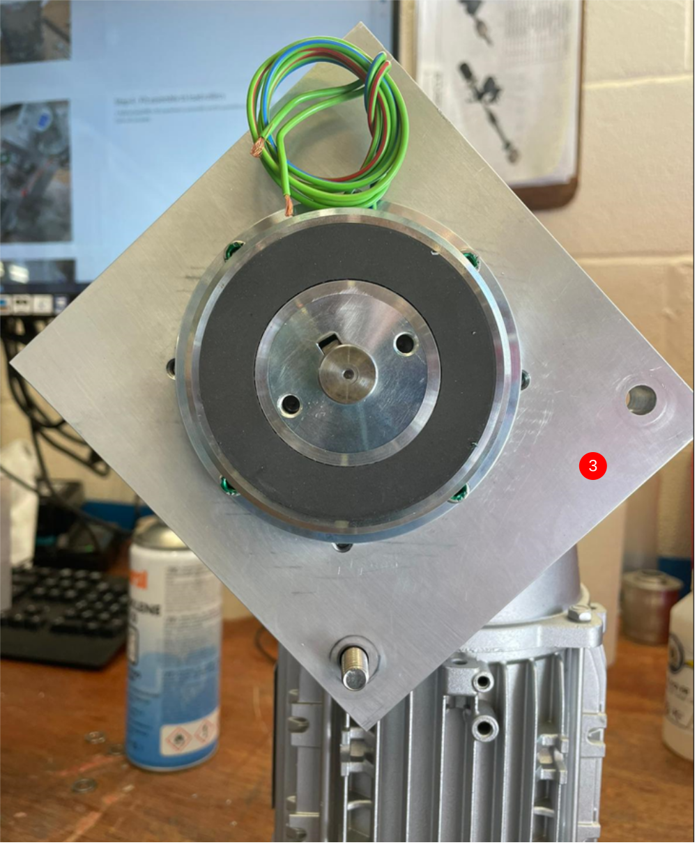
Étape 3 - Mount clutch plate
1 Mount electro clutch backplate to indicated holes using m5 x 16 socket caps 4 off with loctite adhesive 243
2 Slide on second part of clutch and use to align clutch backplate before tightening all 4 m5 bolts to secure back plate in position
3 Orientate electro clutch as shown in picture

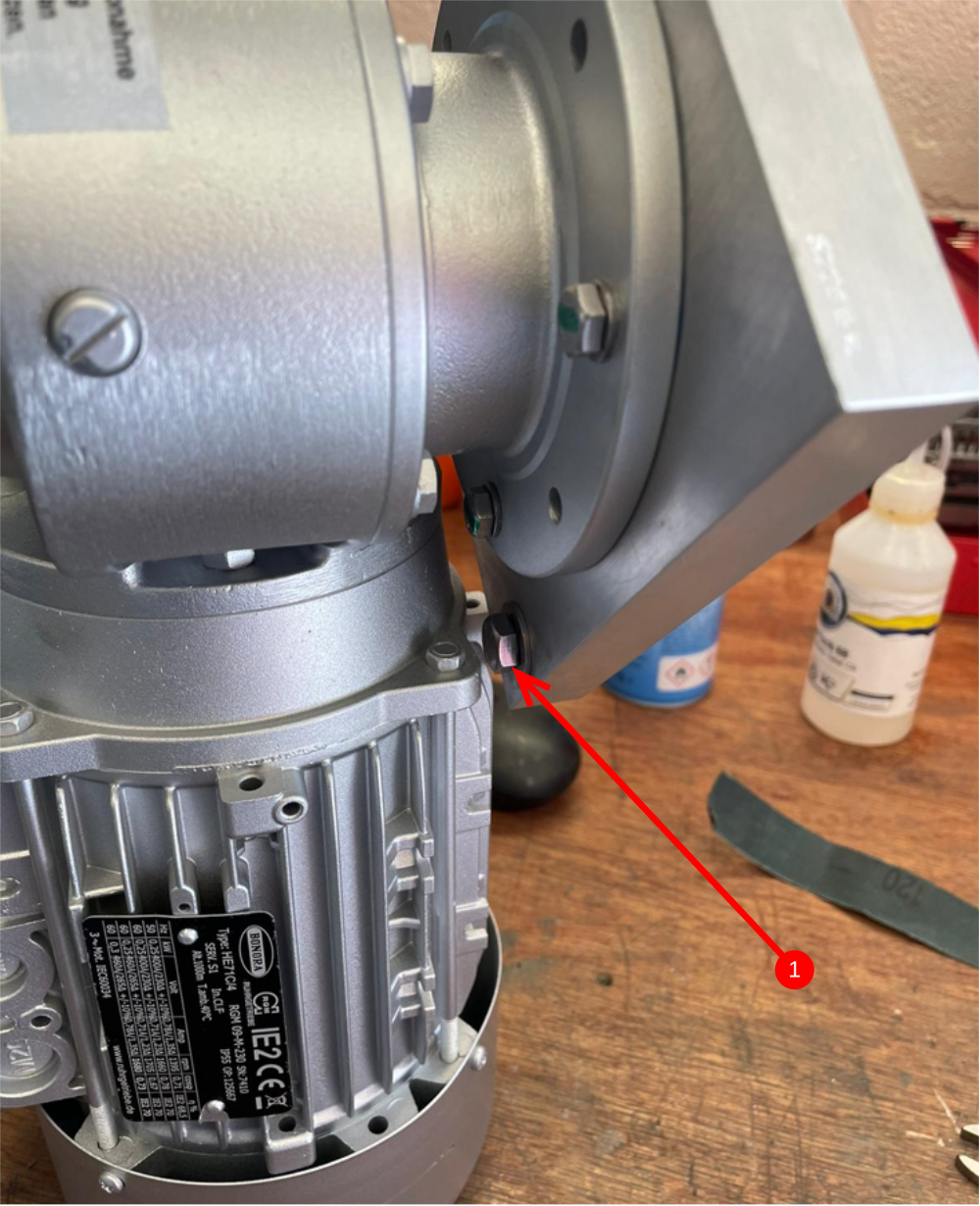
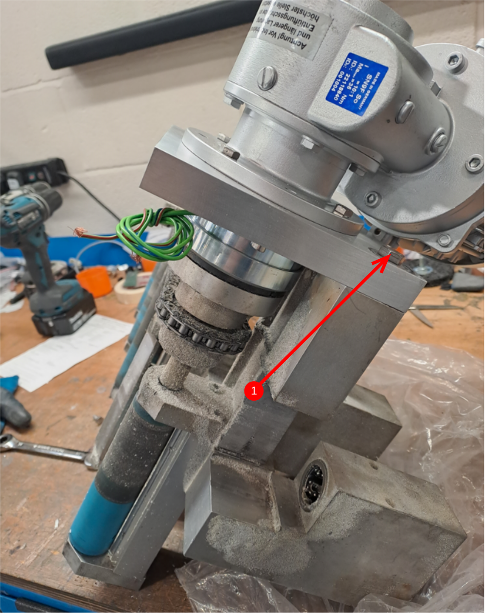
Étape 4 - Fit assembly to load rollers
1 Add second M8 x 40 cap head and A form washer to assembly and fit assembly as shown , then secure both m8 set bolts
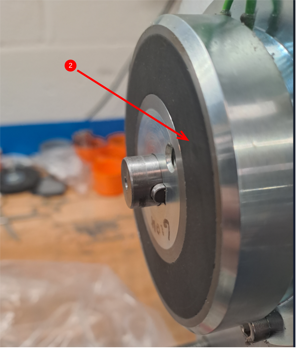
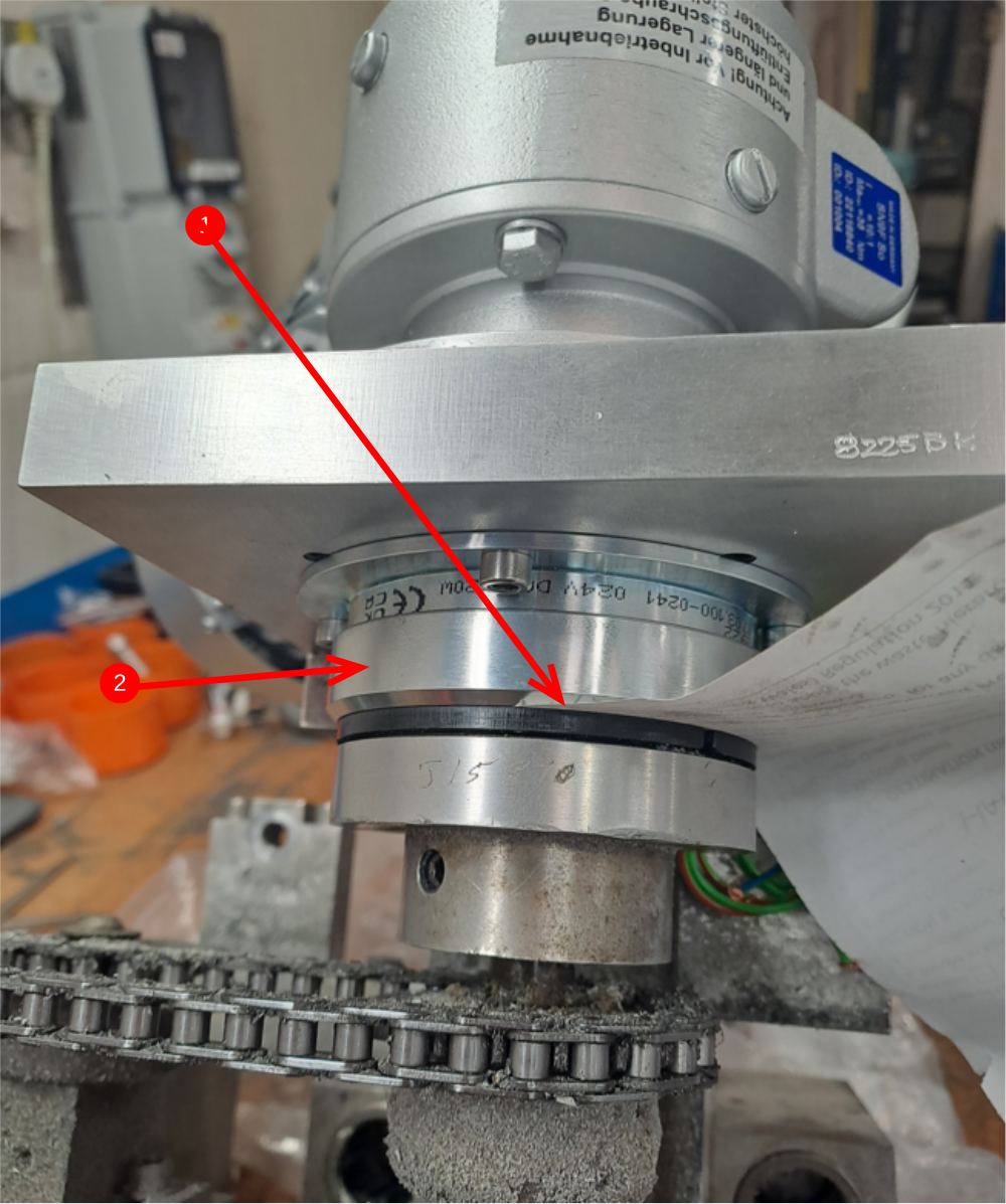
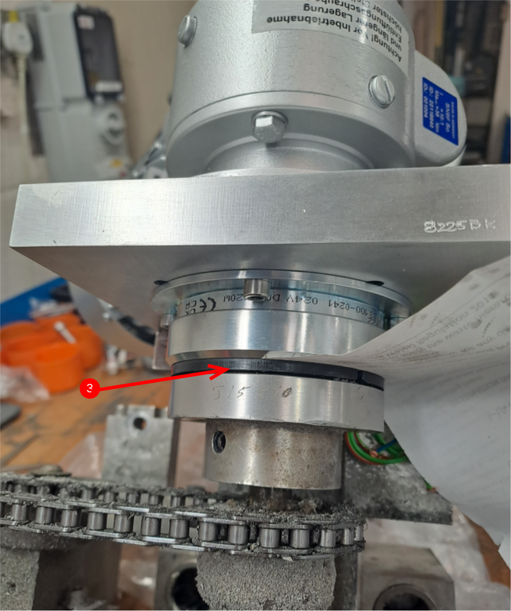
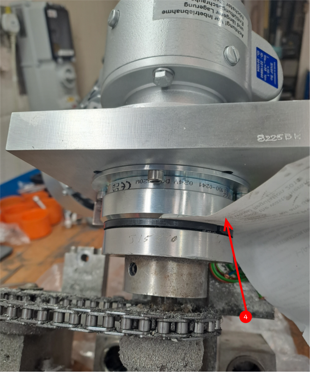
Étape 5 - Set clutch gap
1 Clutch gap should be set to allow correct operation of clutch
2 The part indicated (item 2) should move freely back and forwards onto the friction plate
3 Clutch friction plate (item 3) mounted to the load roller
4 Set the gap between these two parts to the thickness of a piece of paper
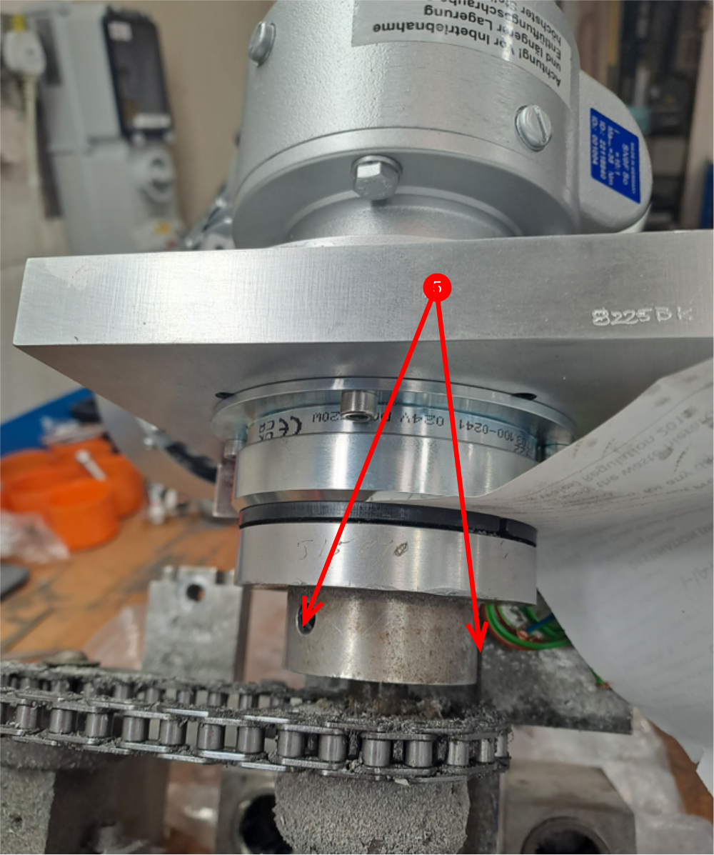
5 The adjustment is achieved by undoing item 5 and moving friction plate towards/away from clutch assembly
Étape 6 - Mechanical installation complete

Draft
 Français
 English
 Deutsch
 Español
 Italiano
 Português