How to check the parallelism of the Stuertz Infeed - GY axis position to backfence


Difficulté
Difficile
Durée
30 minute(s)
Sommaire
- 1 Introduction
- 2 Pièces et outils
- 3 Étape 1 - Ensure a zero GY position at datum
- 4 Étape 2 - Ensure infeed Datum roller aligns with backfence
- 5 Étape 3 - Find range of Adjustment
- 6 Étape 4 - Move the GX axis to a measure position
- 7 Étape 5 - Move GY axis to locate
- 8 Étape 6 - Log GX value vs the GY value in your table / spreadsheet
- 9 Étape 7 - Repeat for different GX axis positions
- 10 Étape 8 - PASS or FAIL
- 11 Commentaires
Introduction
It is important that the parallelism of the GY axis to the backfence is set and maintained along the length of the rack. This tutorial describes how to check this parallelism without the need for measuring equipment
General Procedure
- Find range of adjustment required
- Zero GY axis to ensure range adjustment can be met
- Move to straight edge resting points, Adjust rollers at these points
- Use straight edge between resting points to adjust the other rollers to a fixed datum
Potential Symptoms of a problem
- Gripper cannot pick up offcuts
- Gripper /profile end forced away from backfence
- Accuracy problems
- Gripper wobbles after it has released profile
Use the laptop to enable you to control the Service screen whilst inside the infeed table
The gripper setting jig is used to give an accurate and reliable zero to locate the gripper jaw to. Any piece of aluminium reinforcing box section will also work
- Pièces et outils
Pièces et outils
Gripper Setting Jig 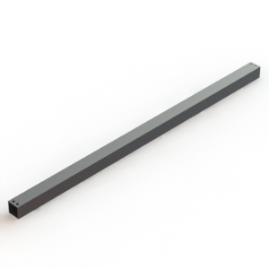

D00154543 Gripper Setting Jig
T0000448 2m Straight Edge 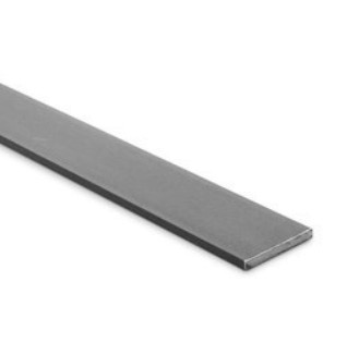

Straight Edge For Checking Alignment
Étape 1 - Ensure a zero GY position at datum
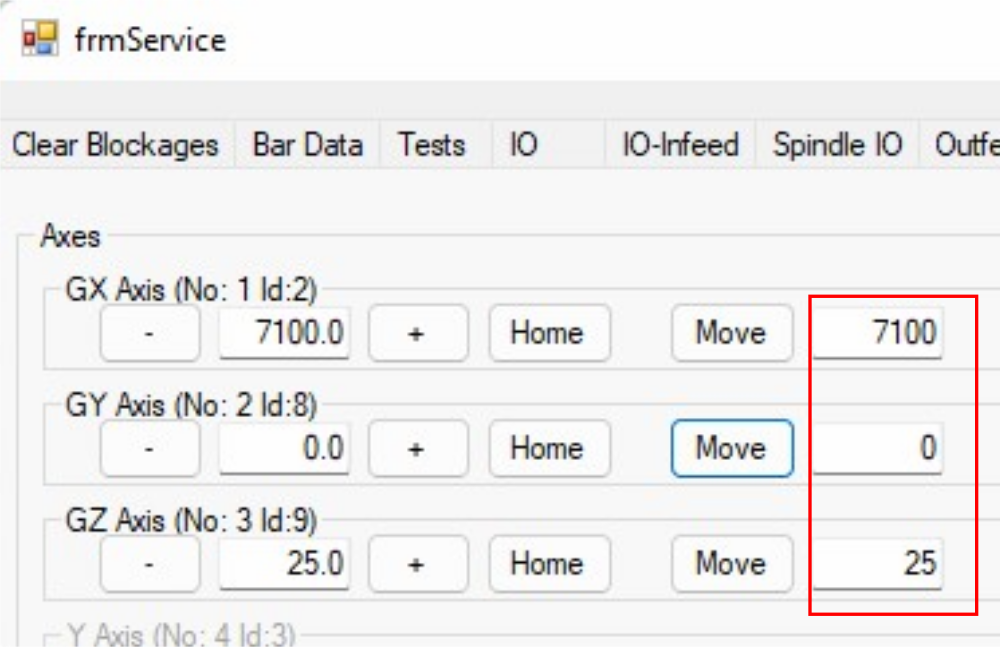
- Datum the machine and move GY axis to zero, GZ to 25
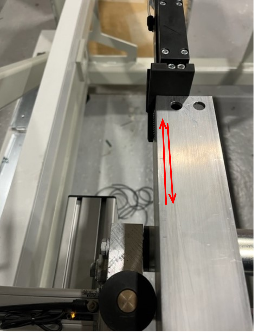
- Place the jig against the backfence and offer it up to the Gripper Jaw
- If the GY datum is set correctly, the rear outer face of the jig should be just in contact with the rear serrated jaw
- If this is not the case, set GY datum correctly
Étape 2 - Ensure infeed Datum roller aligns with backfence
Using the straight-edge, ensure the infeed rollers are 0-1mm behind the machining centre datum rollers .
Étape 3 - Find range of Adjustment
- With the GY at zero, move the GX axis to the last roller before machining centre
- Check the gripper position relative to backfence
- Check to see if this is within the adjustment range of the infeed roller
Étape 4 - Move the GX axis to a measure position
If you have the 2m straight
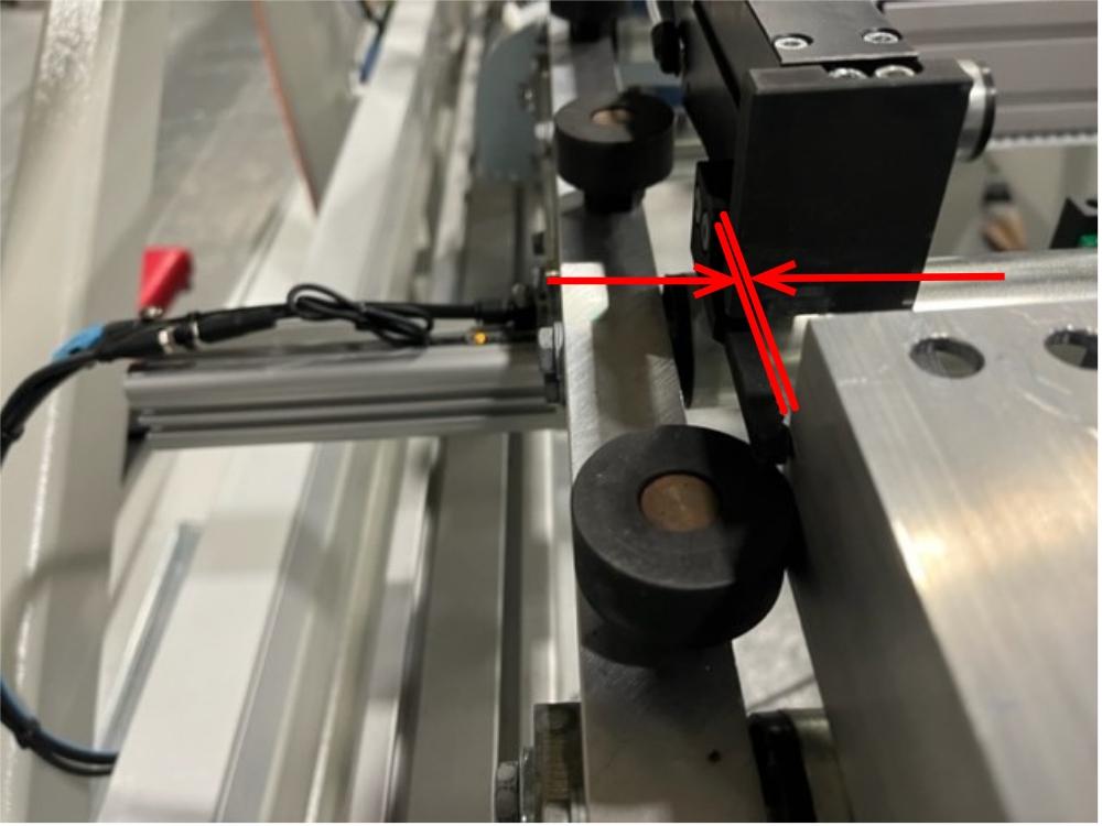
Étape 5 - Move GY axis to locate
If the backfence to gripper is different in this location, it will be visible by a gap or interference to the jig
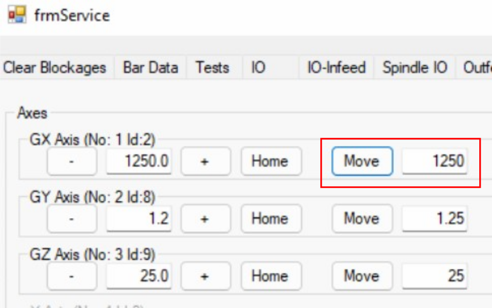
Move GY axis (in 0.25mm increments) to make it touch
Log GX value vs the GY value in your table / spreadsheet
Étape 6 - Log GX value vs the GY value in your table / spreadsheet

Étape 7 - Repeat for different GX axis positions
There may be areas where the offset changes more than others - these deserve more detailed inspection with closer GX axis increments
Étape 8 - PASS or FAIL
PASS
The error should be within +/- 1mm along the rack
In the given example of measurements, the overall range was 0 to +1.5mm
Therefor the GY axis datum should be adjusted by+0.75mm so the error range will then be -0.75mm to +0.75mm(within tolerance
FAIL
If the error variance is outside this range, the backfence will need to be rest to correct this
Draft
 Français
 English
 Deutsch
 Español
 Italiano
 Português