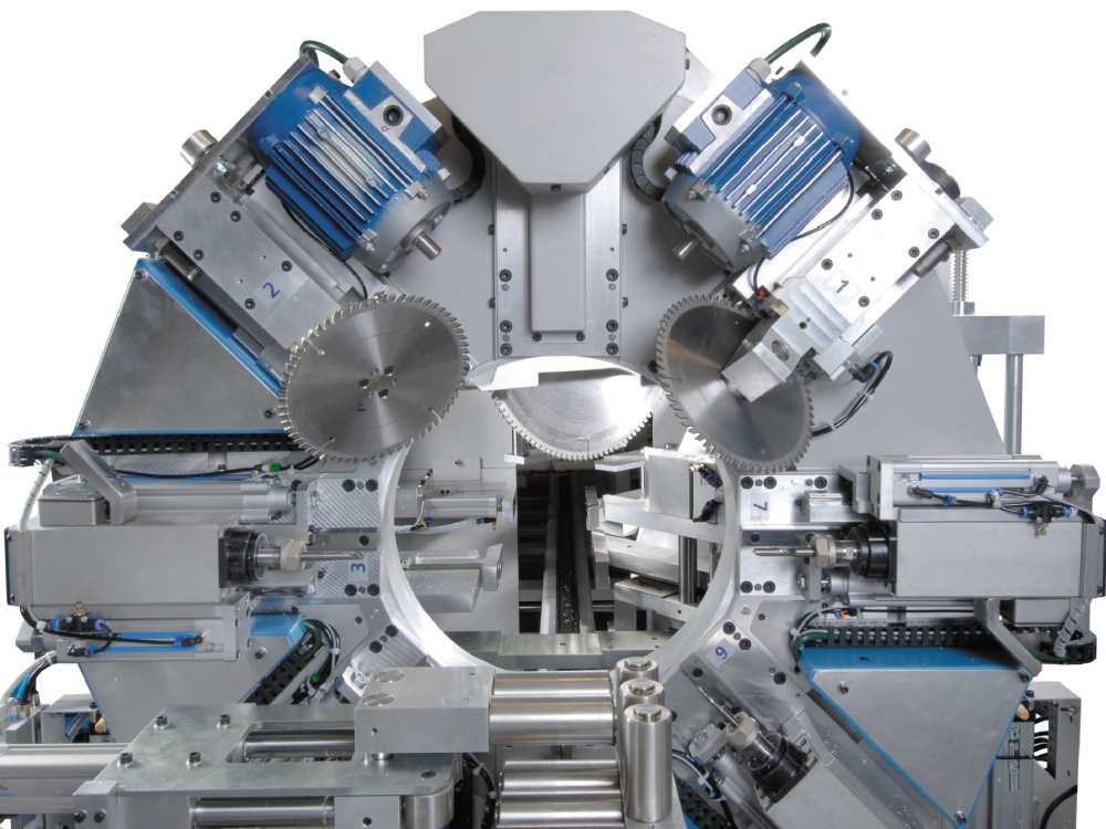
ZX3/Microline/Flowline ZX3 V Notch Blade Setup This module guides the engineer on how to correctly set the V notch blades

Difficulté
Difficile
Durée
30 minute(s)
Introduction
The engineer will need a reasonable mechanical knowledge, and a working knowledge of the operation of the machine.
You will need callipers (+/-0.05mm) and an accurate rule
The setting of the V notch blades on a ZX3 Ring revolves around the setting of two groups of parameters:
- V and W axis positions
- Blade offsets for each blade
The rough position of V and W axes is set first, then the individual blade offsets are set, and finally a test is run to tweak the accuracy to gain perfection.
There are two “tweaking” parameters for each blade. The two parameters are:
- Depth offset – how deep into the bar
- X axis offset – position of point of blade relative to the spindle centreline
- Pièces et outils
Pièces et outils
150mm Caliper 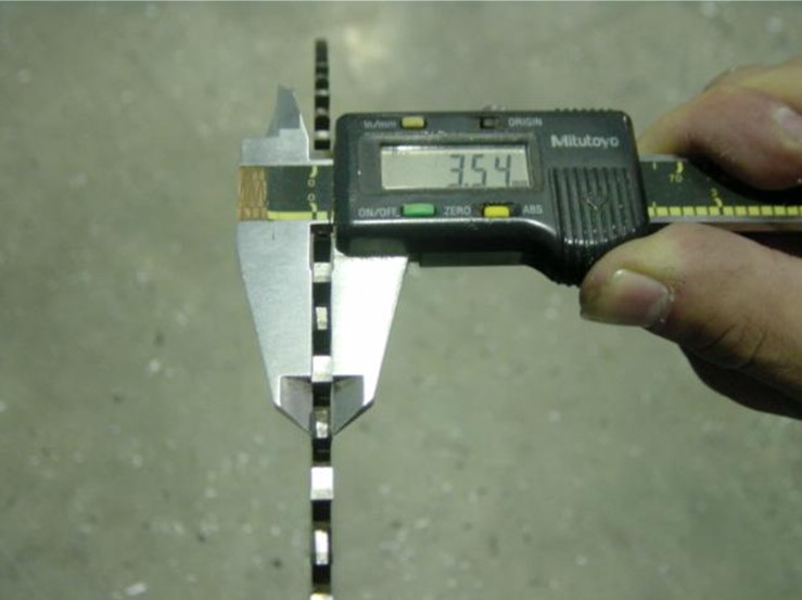

Digital or Analogue Calipers - Accurate to 0.01mm
150mm Rule 

150mm Rule
Étape 1 - Before You Start
- Make sure the Datum is correct first.
- V notch blades are not buckled.
- Check that the profile width is correct for the profile you are testing.
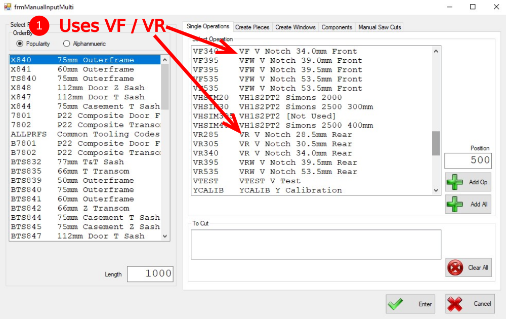
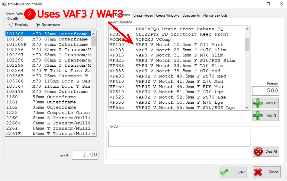
Find out which V Notch files the machine is using by checking the operation setup. A simple way of doing this is shown in the pictures by starting a "Manual Input".
Picture 1 - shows this machine uses VF / VR codes
Picture 2 - shows a different machine using VAF3 codes
Note this "mnd type" for later
Étape 2 - Run a VTest
A calibration mnd file has been written to help line up the x offsets called VTEST. This program creates the following pattern on the bottom of the profile using a 10mm spindle and the notching blades themselves:
Run the VTest operation on a length of large outer frame of at least 1m long. Put the operation at a position of 500mm.
The pattern allows you to measure the offsets required with calipers.

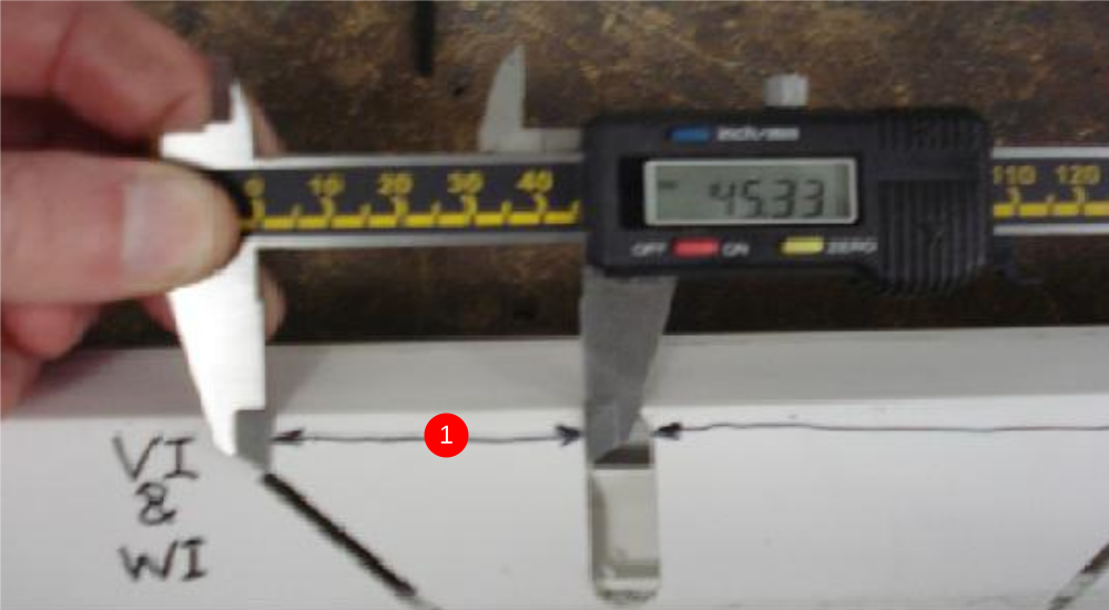
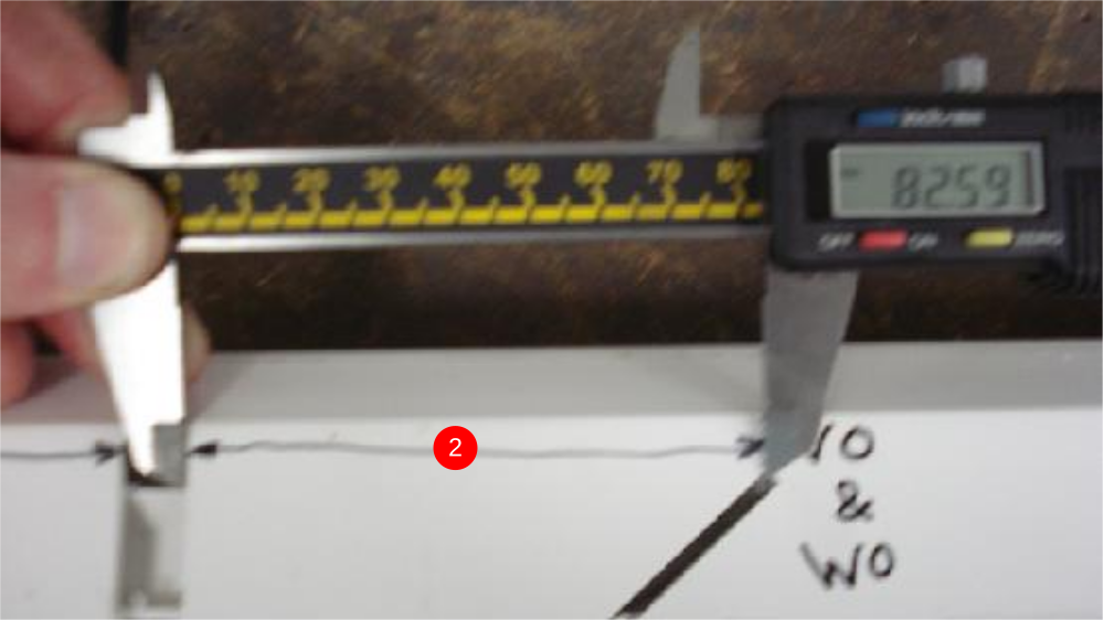
Étape 3 - Measure Results for x Offsets
- Measure between the VI blade and the edge of the 10mm slot – This value is the xoffsetVI (and also the xoffsetWI). (We need to add 5mm to the measured Value). 50.33mm
- Measure between the VO blade and the edge of the 10mm slot – This value is the xoffsetVO (and also the xoffsetWO). (We need to add 5mm to the measured Value) 87.59mm
Étape 4 - Update the Parameters for xOffsets
- Set the xOffsetVI and WI to the new value settings. THIS VALUE IS ALWAYS POSITIVE
- Set the xOffsetVO and WO to the new value in settings. THIS VALUE IS ALWAYS NEGATIVE
Depending on the software version, there are 4 places where these settings are stored / edited
Draft
 Français
 English
 Deutsch
 Español
 Italiano
 Português