Instructions to bench assemble gripper

Difficulté
Moyen
Durée
2 heure(s)
Sommaire
- 1 Introduction
- 2 Pièces et outils
- 3 Étape 1 - Unless otherwise stated
- 4 Étape 2 - ECR Check
- 5 Étape 3 - Fit bushes and bearings
- 6 Étape 4 - check for rework
- 7 Étape 5 - check fitment of D0015084 shafts
- 8 Étape 6 - Check strike plate position
- 9 Étape 7 - Quality check !!
- 10 Étape 8 - Caution
- 11 Étape 9 - Assemble load switch plate
- 12 Étape 10 - Quality Check
- 13 Étape 11 - Fit Sensor
- 14 Étape 12 - Fix X44 cable
- 15 Étape 13 - How to correctly assemble and fit reed switch to cylinder
- 16 Étape 14 - How to correctly assemble and fit reed switch to cylinder
- 17 Étape 15 - Assemble cylinder P0001120
- 18 Étape 16 - Assemble grip pin assembly
- 19 Étape 17 - Mount grip pin assembly to grip slide
- 20 Étape 18 - Quality instance !
- 21 Étape 19 - Assemble main frame of gripper assembly
- 22 Étape 20 - Fit link bars to assembly
- 23 Étape 21 - Fit Cylinder assembly
- 24 Étape 22 - Add mounting brackets
- 25 Commentaires
Introduction
Tools Required
External circlip pliers
Standard Hex key set
Standard spanner set
Reed switch setting box
Hammer
Standard screwdriver set
Rule
Parts Required
B0001106 x 20
D0015095 x 8
D0015096 x 2
D0015086 x 1
B0000034 x 2
D0015084 x 2
D0015083 x 1
D0015082 x 1
E0000366L x 1
B0001182 x 2
M0001182 x 2
D0015756 x 1
P0001013 x 1
P0001041 x 1
P0001128 x 1
P0001198 x 2
P0001120 x 1
D0015431 x 1
B0000437 x 1
D0015430 x 1
D0015090 x 2
D0015085 x 1
D0015102 x 2
D0015103 x 2
D0015104 x 2
D0015170 x 2
P0000049 x 1
D0015097 x 2
D0015100 x 2
D0015292 x 1
E0000336 x 1
E0001069 x 1
A0001044 x 4- Pièces et outils
Pièces et outils
[[Item:|]] A fatal error occurred in the #info parser function
Étape 1 - Unless otherwise stated
Use Loctite 243 on all fasteners
Pen mark all bolts,nuts and fasteners once finalised

Étape 2 - ECR Check
Ensure ecr change is present on D0015082
Indicated hole must be tapped tru as shown.
If hole is not tapped thru, please rework by hand and record as rework

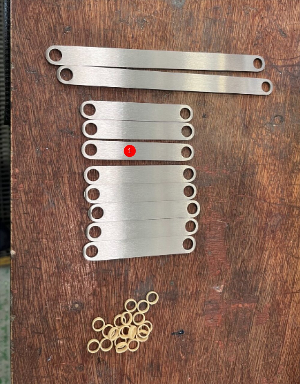
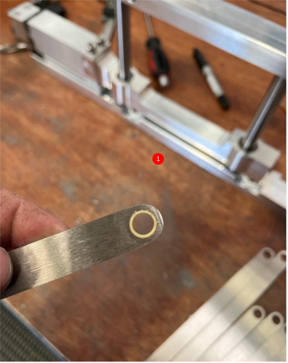
Étape 3 - Fit bushes and bearings
1 Fit bushes B0001106 (20 off) to
8 off D0015095 link bars
2 off D0015096 link bars
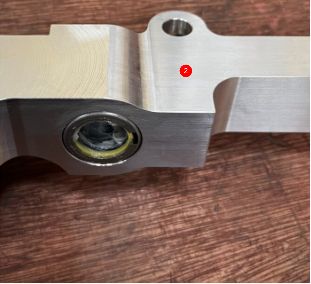
2 Fit bearings B0000034 x 2 into D00015086 grip slide body. Use grease to lubricate bearing before assembly
Étape 4 - check for rework
Check that part D0015082 has been manufactured to the listed details highlighted in drawing attached to this step. If M4 and M5 holes are not present, rework and record time

Étape 5 - check fitment of D0015084 shafts
Check shafts fit correctly into bores of D0015082 gripper bottom bar and D0015083 gripper upper bar

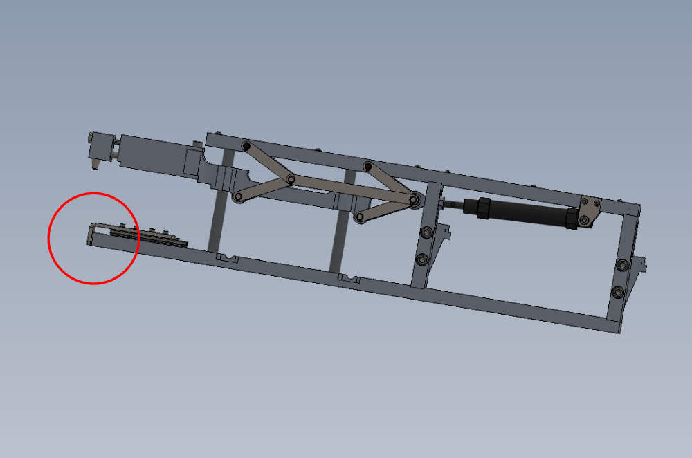
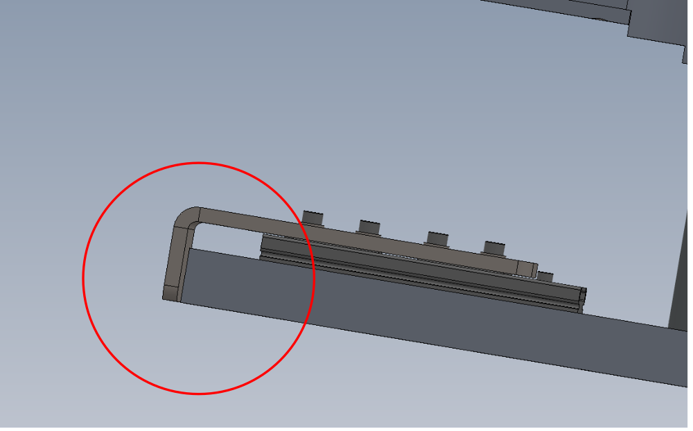
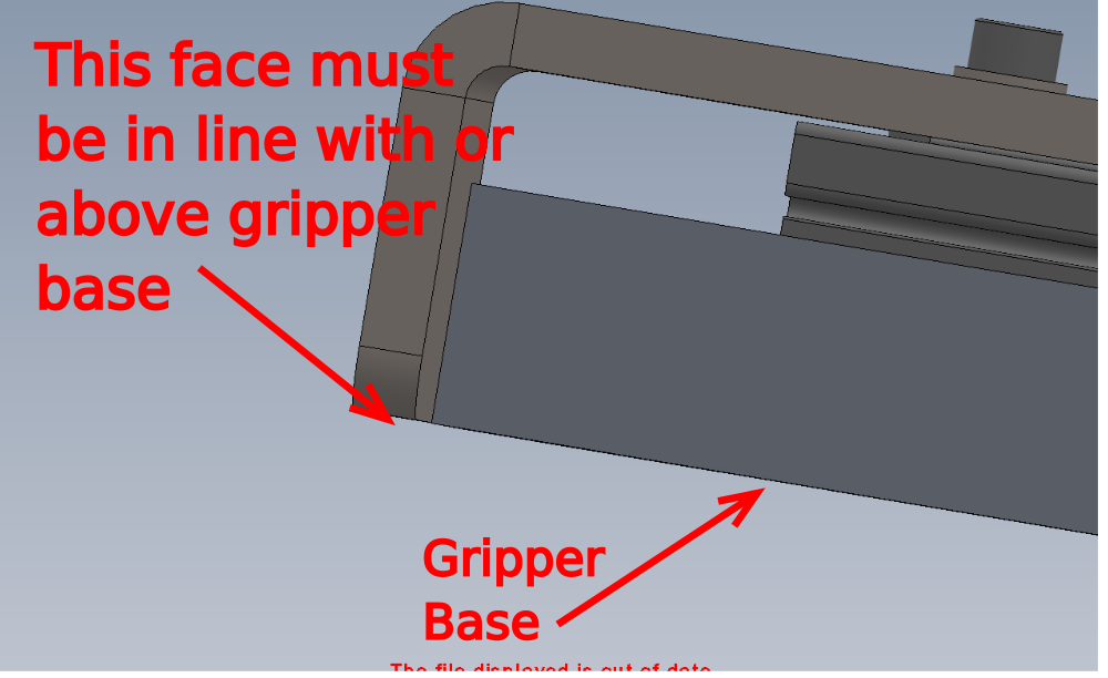
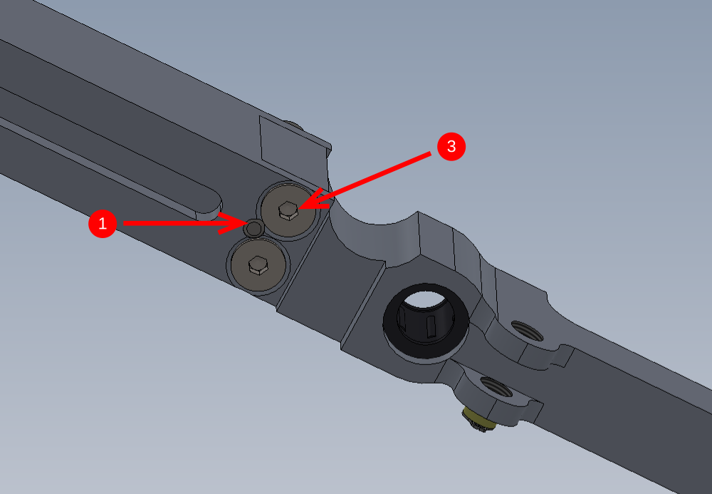
Étape 6 - Check strike plate position
When assembling next step, check position of strike plate at indicated point.
No overhang below bottom face of gripper base should be present.

Étape 7 - Quality check !!
Several instances of the following step have been encountered.
Please ensure all fixings are sufficiently tight and adequate Loctite 243 is used on ALL fasteners
Étape 8 - Caution
The load switch must be assembled that enables free running and not tight spots to be encountered when operated. Please ensure assembly guidance is followed and adhered to. If any issues arise please advise supervisor for correct action

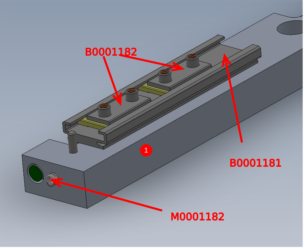
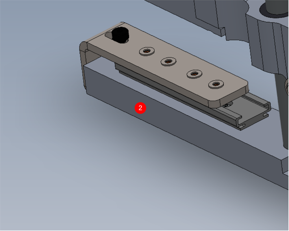
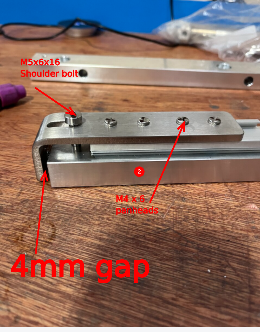
Étape 9 - Assemble load switch plate
1 Use M4 x 6 panhead to attach B0001181 rail to gripper base
Fit M0001182 spring to main base
2 Use M5x 6 x 16 shoulder bolt and M4 x 6 pan heads to attach D0015756 lever to assembly
Check gap indicated is 4mm
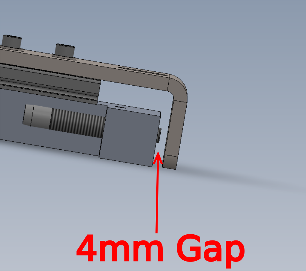
Étape 10 - Quality Check
It is vital the above fitted shoulder bolt is correct.
Bottom of shoulder bolt should meet face of gripper base as shown
No thread should be visible when fitted correctly

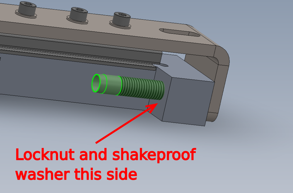
Étape 11 - Fit Sensor
1 Add cable markers to E0001069 cable , Mark as X44 both ends
2 Attach above cable to E0000336L and fit as shown with 1 off supplied lock nut and shakeproof washer on the indicated face
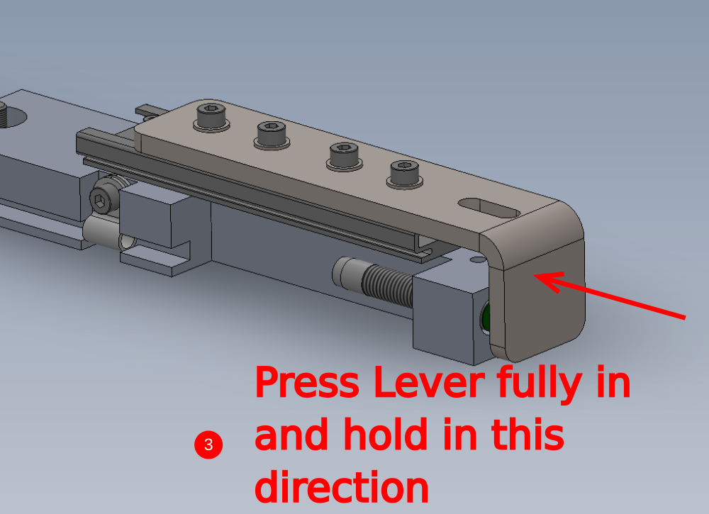
3 Set Sensor position as follows
Press lever fully in direction shown
Adjust sensor to touch rear of profile present lever
Adjust sensor back half a turn
Lock of lock nut to hold position ( Do not over tension )
Check, when lever is pressed fully back, the sensor should be close to the profile present lever but not touching
Étape 12 - Fix X44 cable
Use 4 off A0001044 p clips 4 off M4 x 12 socket caps and captivate X44 cable at points shown

Étape 13 - How to correctly assemble and fit reed switch to cylinder
Due to many quality instances of incorrect fitting, please ensure the following steps are strictly adhered to
1 Remove grubscrew from P0001013 reed switch and dispose
2 Use metal retainer clip from P0001041 kit
3 Fit metal clip to reed switch as P0001013 reed switch as shown
4 Inset clipped reed switch into P0001041 bracket as shown, noting correct orientation


Étape 14 - How to correctly assemble and fit reed switch to cylinder
- Remove screw and band from P0001128 kit
- Bend ends of metal band to 90 degrees by hand ensuring thick metal plate is orientated as show
- Fit screw through clearance hole and position reed switch assembly as shown
- Attach to cylinder and fix in position with screw


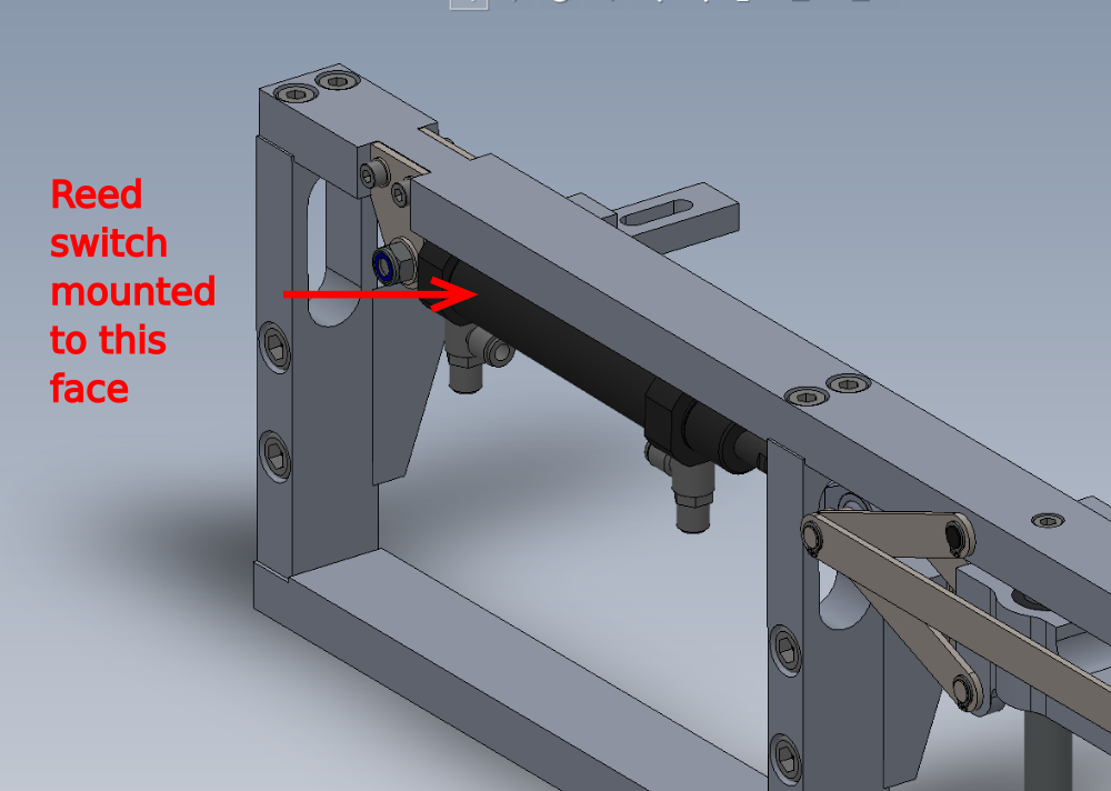
Étape 15 - Assemble cylinder P0001120
Fit air fitting P0001198 to cylinder
Remove 32mm nut from cylinder and discard
Mount reed switch and band (P0001041 x 1 P0001013 x 1 P0001128 x 1) to cylinder in piston retracted position , mark as X283. Orientate as shown , reed switch should face
Use switch testing box to set correct position of reed switch
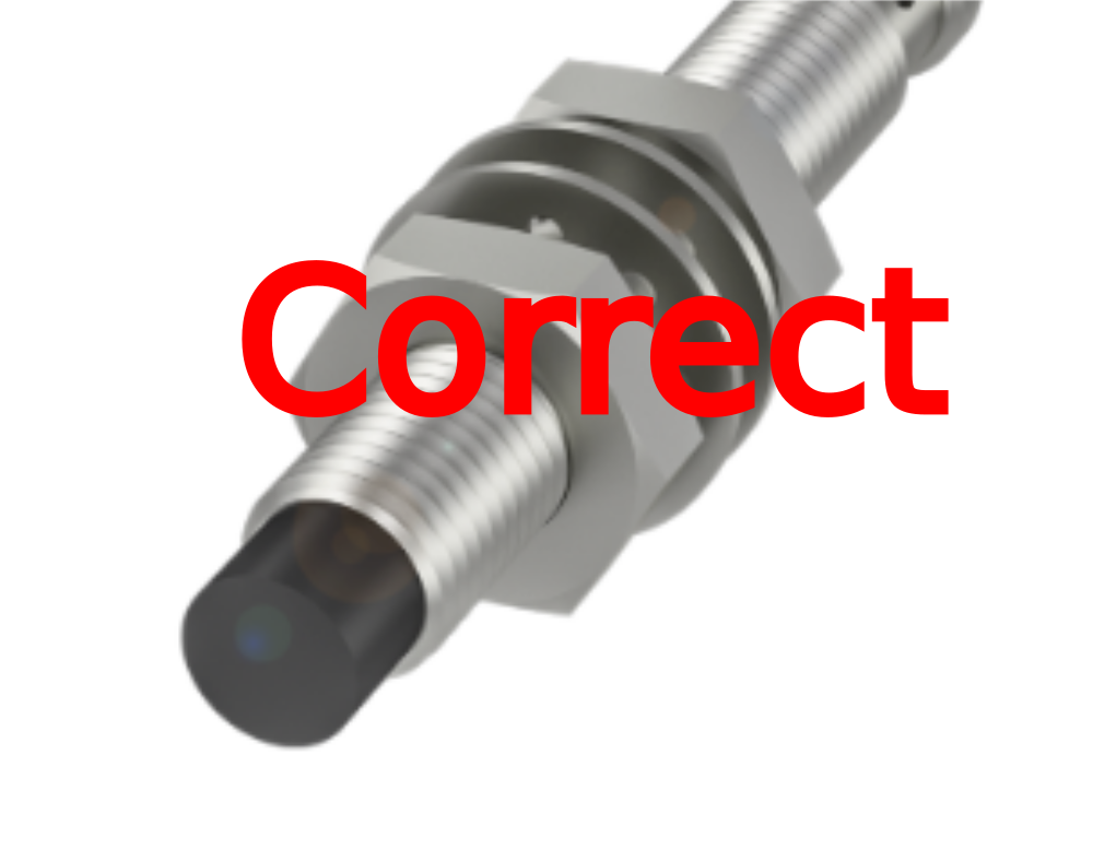
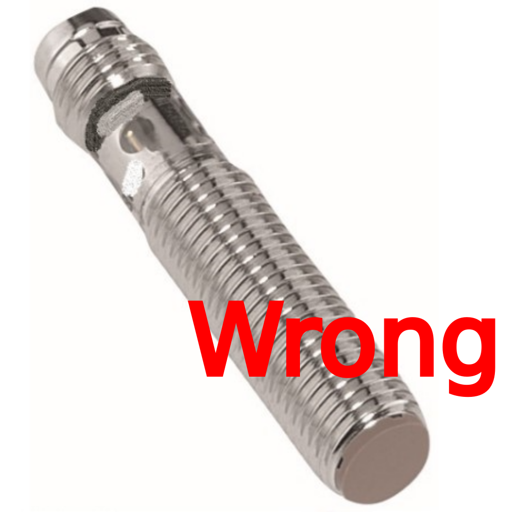
Ensure sensor is orientated the correct way, so adjustment screw can be accessed if needed. Sensor should be at 90 degrees position to top of cylinder , not as shown in example of wrong mounting


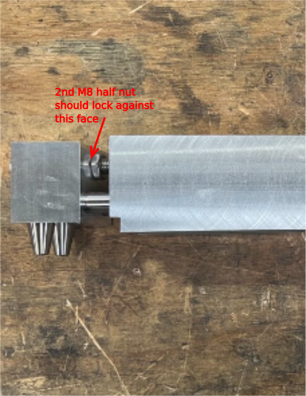
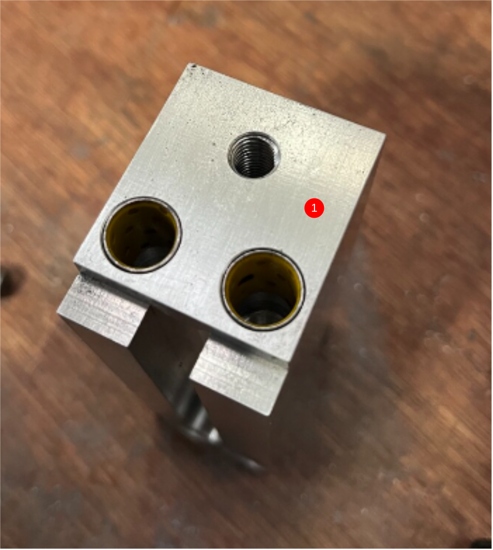
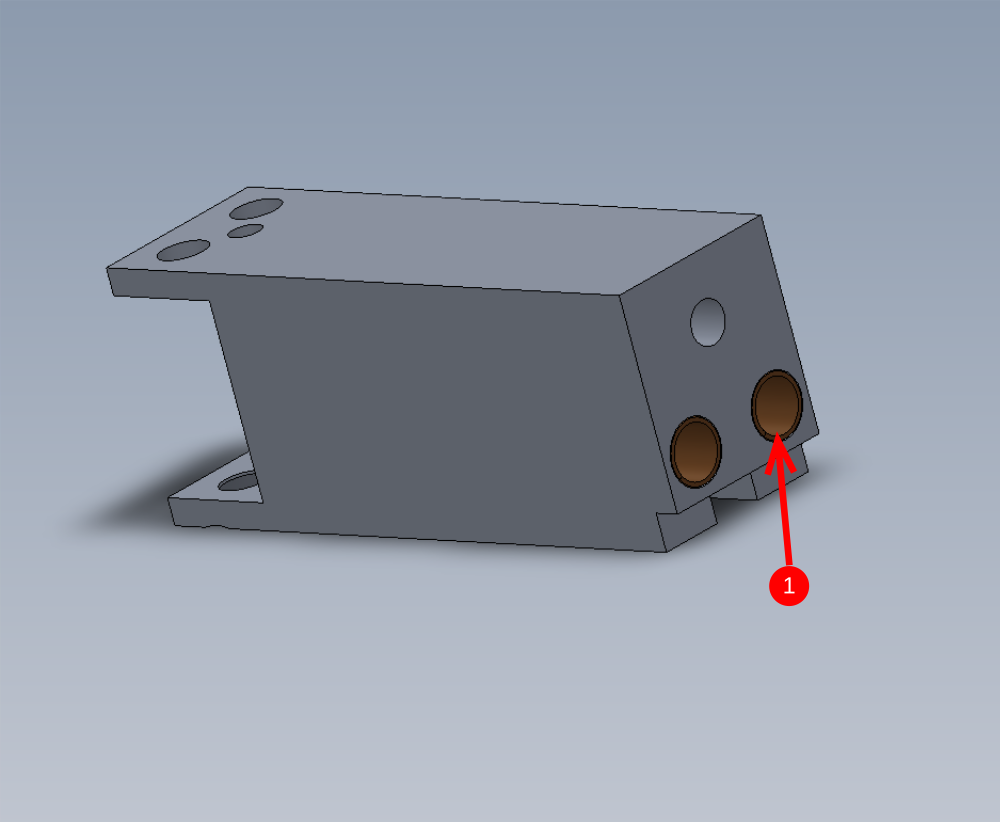
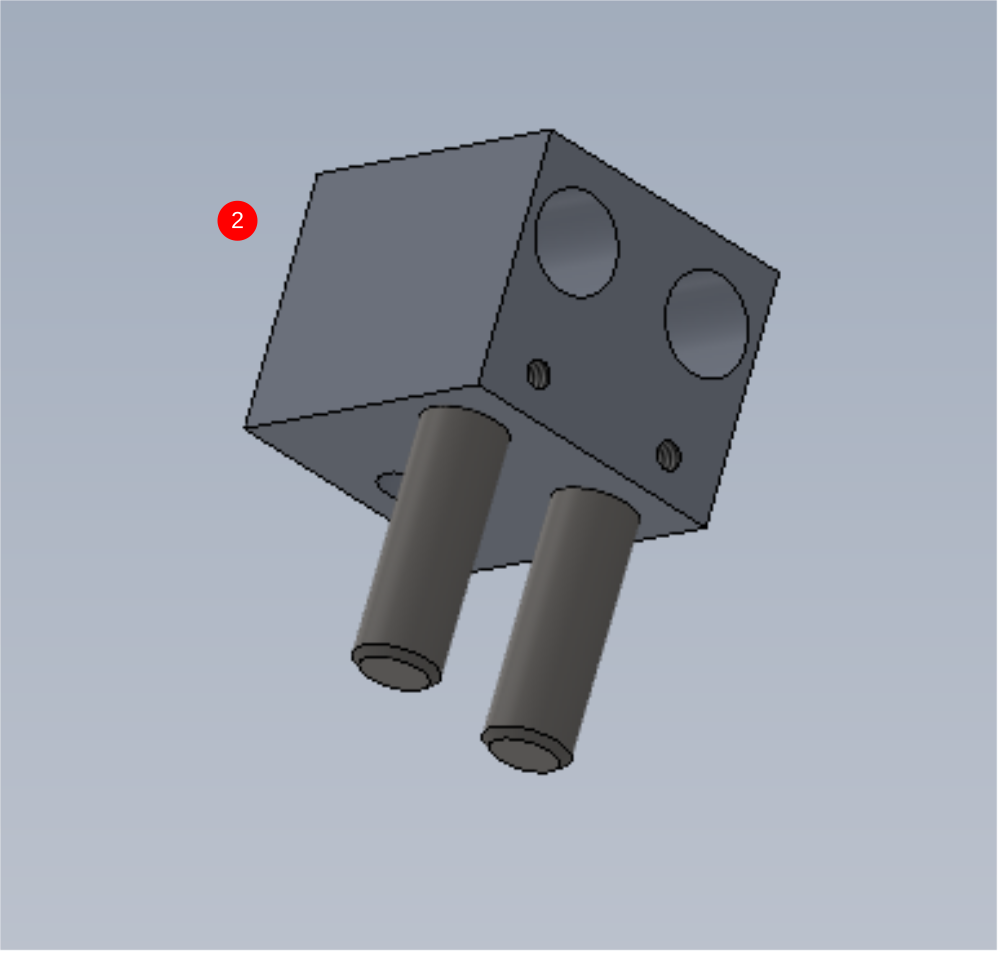
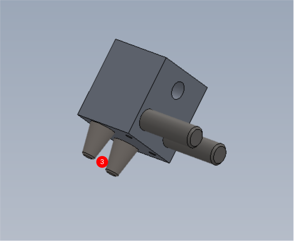
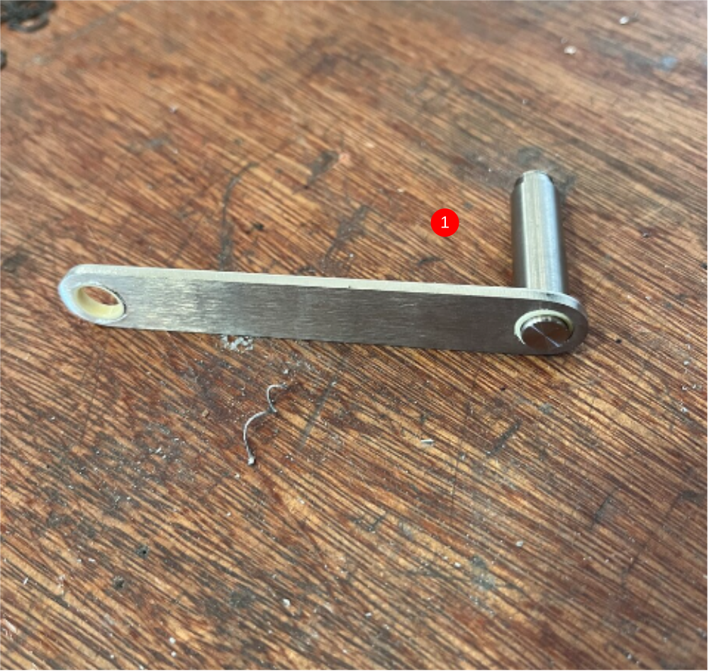
Étape 16 - Assemble grip pin assembly
1 Fit bushes B0000437 x2 to body D0015431
2 Use 2 off 10mm x 40mm dowel. Ensure dowels fit correctly in nose D0015430. Check dowels have pushed all the way to the bottom of the bore . Secure with 2 off M4 x 4 grubscrew
3 Fit D0015090 Grip pin x 2 and secure with M5x 16 socket cap
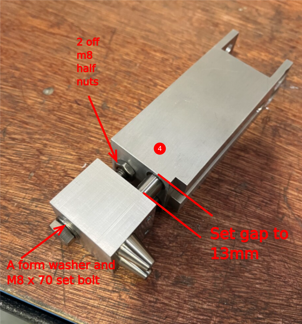
4 Combine together and use m8 x 70 set bolt, a form washer and 2 x m8 half nuts to secure. Set gap to 13mm and lock all fasteners. Recheck measurement. Tolerance +-0.1mm
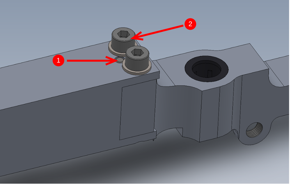
Étape 17 - Mount grip pin assembly to grip slide
Combine parts
1 Use 2 off 6mm x 20mm dowels to align ( 1 top and 1 bottom)
2 M8 x 16 socket cap and A form washer
3 M8 x 20 countersink

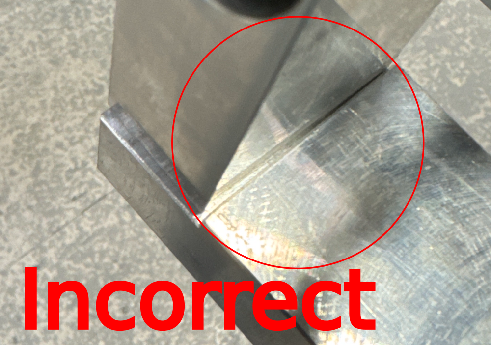
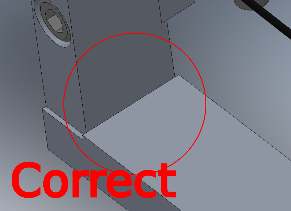
Étape 18 - Quality instance !
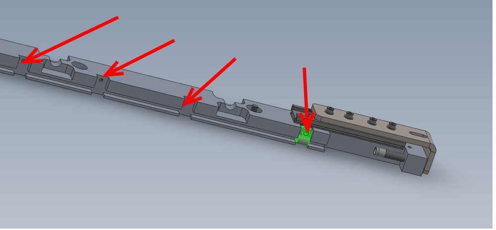
Please ensure when assembling components that attention is paid to mating faces and the correct alignment
These rebates are to aid assembly and ensure squareness when built
Faces must be butted to each other to be assembled correctly
Please see picture for an example of incorrectly assembled mating faces and also correctly assembled
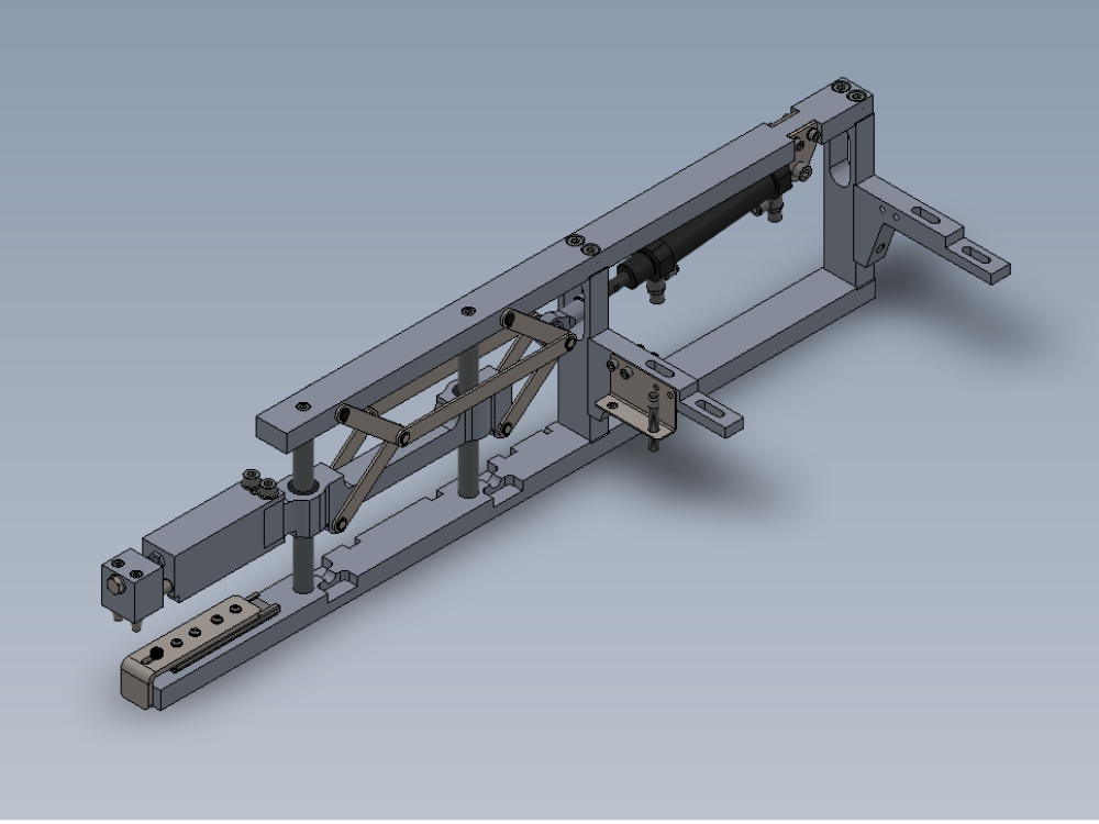
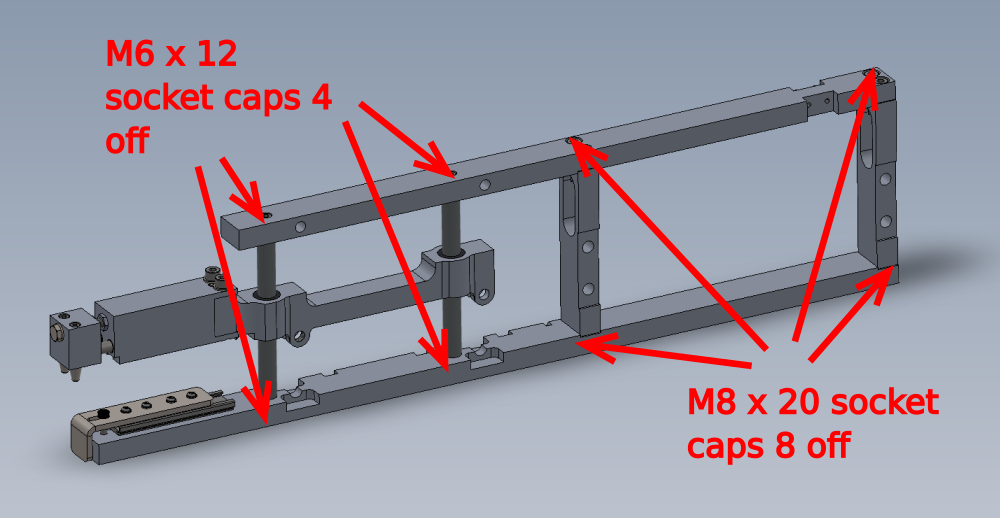
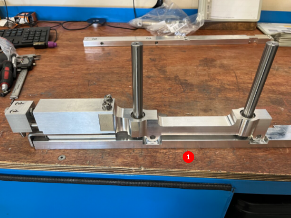
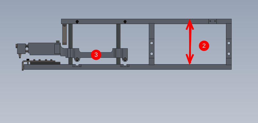
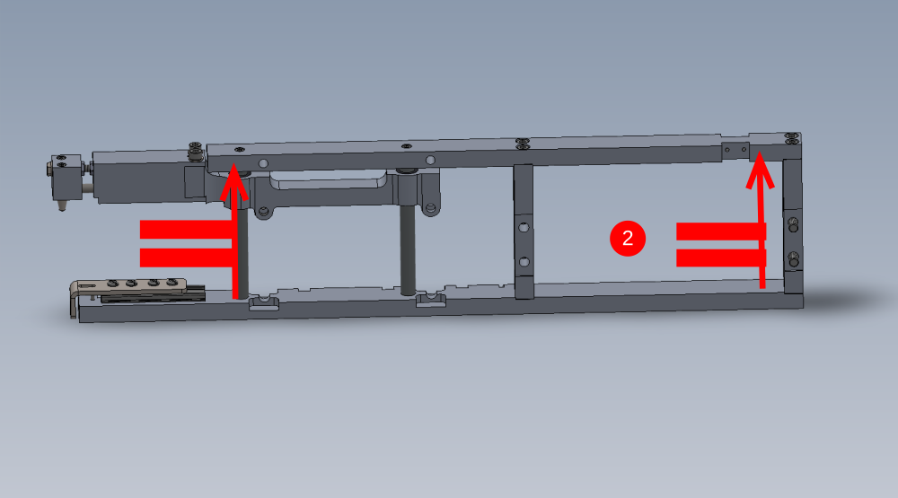
Étape 19 - Assemble main frame of gripper assembly
Use 2 off D0015085
1 Assemble as shown using 8 off M8 x 20 socket caps and 4 off M6 x 12 socket caps
2 Check top and bottom bars are parallel
3 Check grip slide moves freely up and down
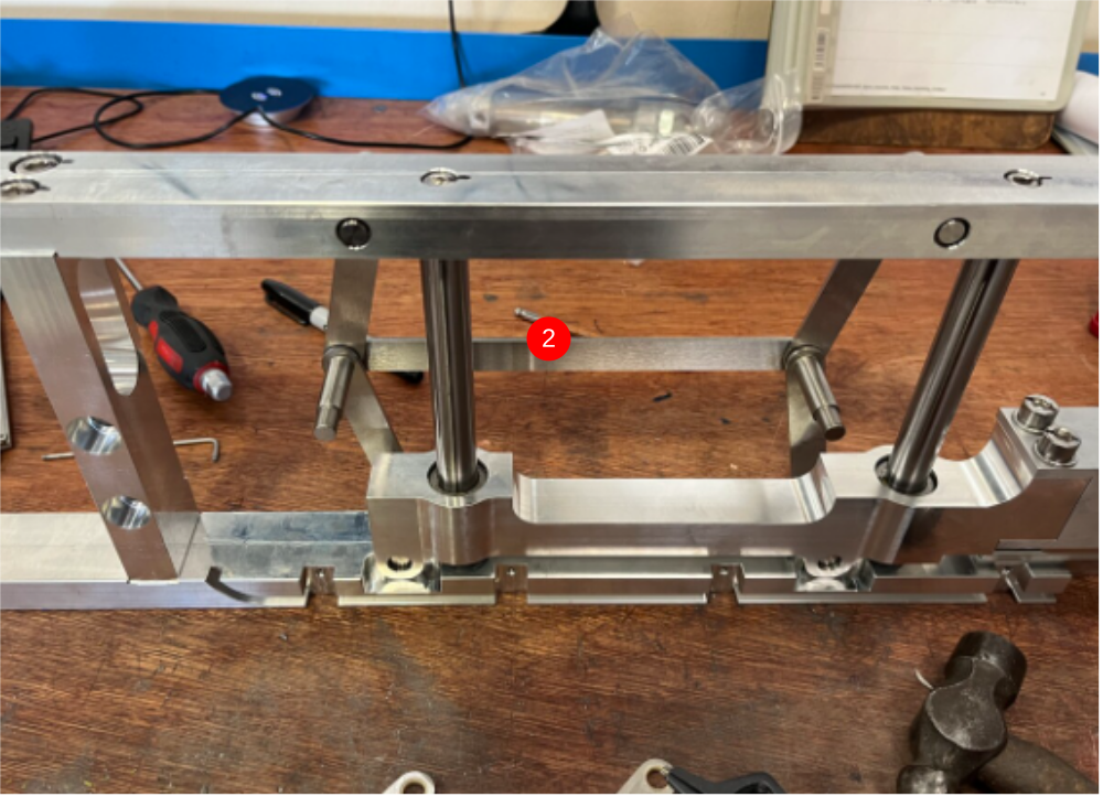
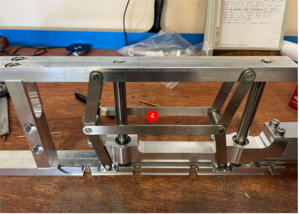
Étape 20 - Fit link bars to assembly
1 Use 2 off D0015103 and 8mm external circlips (B0000200) and assemble two off as shown
2 Use 2 off D0015102, 2 off D0015104 and assemble as shown with 8mm circlips
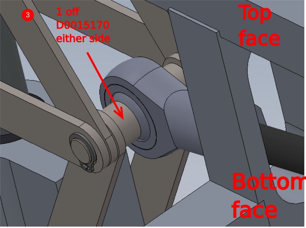
3 Use 2 off D0015170 gripper spacers and P0000049 spherical end and add as shown
4 Add remaining link shafts and circlips

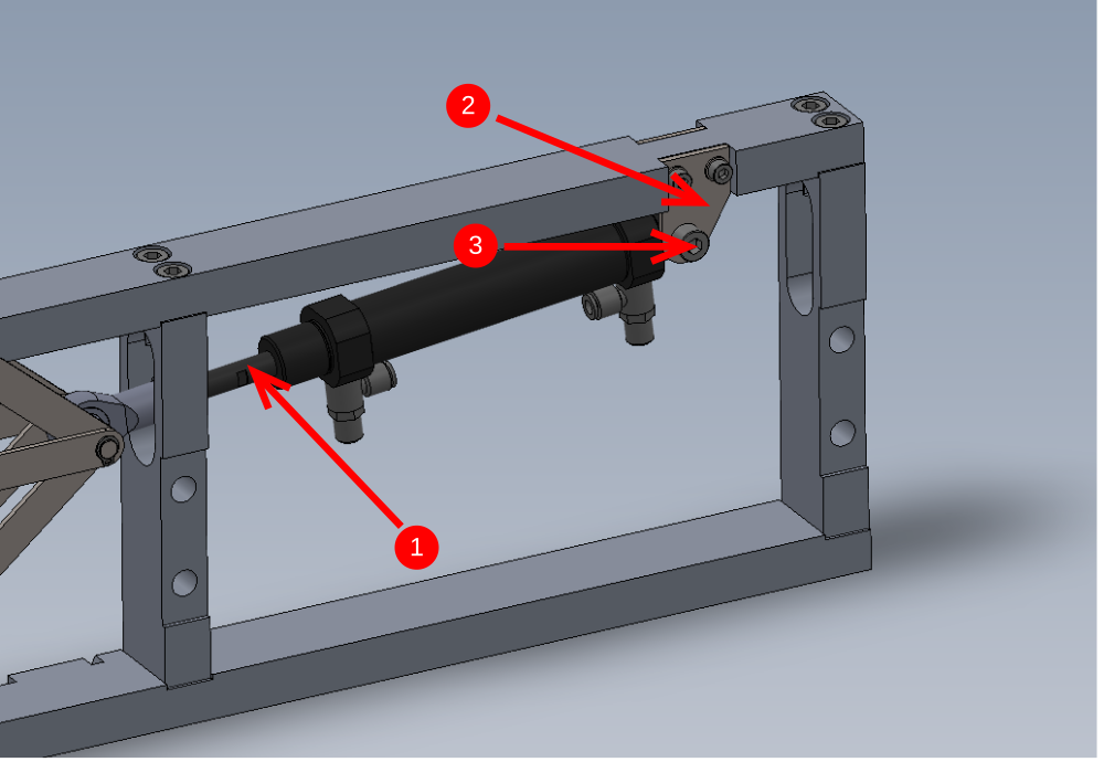
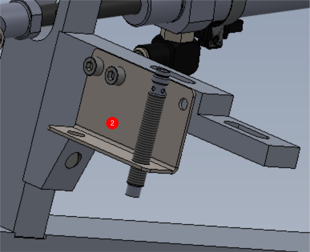
Étape 21 - Fit Cylinder assembly
Fit assembled cylinder unit to gripper frame
1 Wind cylinder thread into spherical bearing lock cylinder nut off with 1 thread of cylinder piston exposed behind lock nut
2 Use M5 x 10 with a form washer to secure D0015097 2 off mounting plates
3 Use M8 x 30 with M8 nyloc nut to secure cylinder to brackets
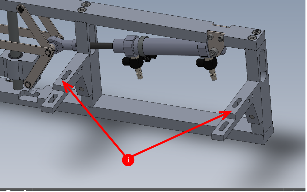
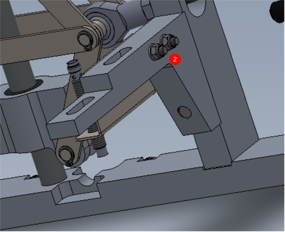
Étape 22 - Add mounting brackets
1 Fix as shown 2 off D0015100 brackets with 4 off M10 x 40 socket caps
Do not apply adhesive or final tension to these fasteners
2 Mount Sensor bracket D0015292 with 2 off M5 x 30 socket caps, A form washers and M5 Nyloc nuts. Mount E0000336 as shown using both lock nuts and shake proof washers provided with sensor
Draft
 Français
 English
 Deutsch
 Español
 Italiano
 Português