Cette page fournit une simple interface de navigation pour trouver des entités décrites par une propriété et une valeur nommée. D’autres interfaces de recherche disponibles comprennent la page recherche de propriété, et le constructeur de requêtes ask.
Liste de résultats
- Autocut Taking A Backup + (Backing up is vital to ensure your data is safe in case there is a failure of the PC or Hard Disk Drive)
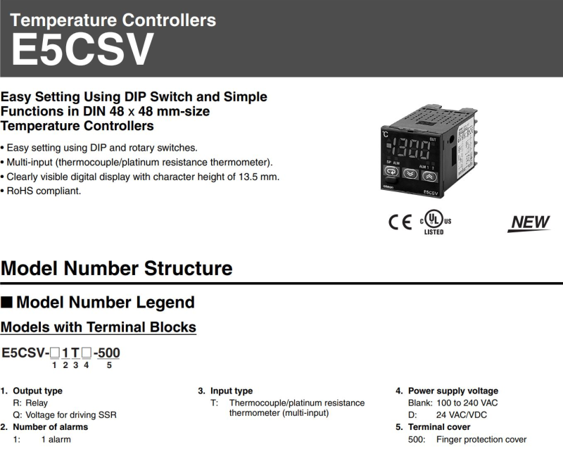
- Omron E5CVS PV Shift + (<div class="annotatedImageDiv" typeof=" …
) - Upgrading Autoflow TwinCAT2 to Win10 and TwinCAT3 + (<div class="annotatedImageDiv" typeof=" … Autoflows from A2001 to A2015 were initially produced with TwinCAT2 software. This has now been superseded with TwinCAT3 which then has the benefit of compatibility with version 6 front end software.

The original PC cannot be used because
*It is not powerful enough to run v6 front end
*The operating system cannot be upgraded to Windows 10
*It cannot be upgraded to TwinCAT3
The Beckhoff C6015 PC has been chosen to be the replacement PC. It is compact, yet powerful enough to run the v6 front end and TwinCAT in the same
. It has an upgrade to 1.9Ghz 4 core processor.
Because it has a limited 40Gb SSD memory, a compact 64Gb memory stick is inserted into the USB 3.0 port. This acts as a separate drive for the DDRIVE dynamic storage for all machine setup. The internat drive is for the Operating System only. This mimics the current Autoflow setup of a remote Camera PC, hence the camera PC can be retired after the upgrade
era PC, hence the camera PC can be retired after the upgrade<br/>) - R0015342 Bench Assemble Outfeed Parts + (<nowiki>'''<u>Tools Required&l …
'''Tools Required''' gt;<br />P0001068 Valve Base: Type 41 2 Position Ø6 x 1<br /><br />P0001085 Fitting: SMC 1/4" to Ø8 Swivel Elbow x 1<br /><br />P0001163 1/4 bsp male silencer x 2<br /><br />P0001186 Valve/ 5/2 smc x 2 <br /><br />P0001198 1/8 bsp 6mm speed controller x 4<br /><br />P0000394 reed switch holder x 2<br /><br />P0000444 Reed switch pneumax x 2</nowiki>)
Standard Hex Key set
Standard spanner set
Standard screwdriver set
Bearing press
Test box for cylinder switch function
'''Parts Required'''
B0000034 Linear Bearing: Ø16 x 30 Compact (Metal Case Only) x 8
B0000236 90 Deg Grease Nipple M6 ST/ST x 4
D0004311 Side Eject Block x 2
D0004591 Side Eject Housing x 2
D0004592 Eject Housing Plate x 2
D0005200 Safety Dead Stop Block x 1
D0005201 Safety Dead Stop Backer (5357) x 1
D0005202 Safety Dead stop Yoke (5358) x 1
D0005203 Safety Slider Cap x 2
H0004626 Shaft 16mm: 275 Eject Push x 4
M0000101 Compression Spring 11 D 15 D 25 Long x 1
P0000035 Cylinder 25x160 x 2
P0000174 Fitting: Plug 1/4'' BSP (Grubscrew Type x 2
P0000201 Flow Controller 6mm x M5 Elbow x 2
P0000367 16mm bore X 125 stroke with rod end clevis x 1
P0000369 Clamp to suit P0000367 x 2
P0000327 Reed Switch: Pneumax 1580U (5.0m Lead) x 2
P0001068 Valve Base: Type 41 2 Position Ø6 x 1
P0001085 Fitting: SMC 1/4" to Ø8 Swivel Elbow x 1
P0001163 1/4 bsp male silencer x 2
P0001186 Valve/ 5/2 smc x 2
P0001198 1/8 bsp 6mm speed controller x 4
P0000394 reed switch holder x 2
P0000444 Reed switch pneumax x 2 - R0015316 V notch Final Assembly Part 2 + (15/09/2025 Moved to Confluance Click [https://stuga-ltd.atlassian.net/wiki/external/NTcwZDVkYWY1NWI0NGQwM2IyZTQ0ZTQ4NjQ3OWYzMDE Here])
- R0000963E Bench Assemble Z axis Components + (03/09/2025 Moved to Confluance Click [https://stuga-ltd.atlassian.net/wiki/external/NzA1MmFjYThjZTMxNGM4Zjg3MzkyZmUyZWE0YjlhNTQ Here]<br/>)
- R0002913E Install and Align Rotary head Subframe PART 2 + (04/09/2025 Moved to Confluance Click [https://stuga-ltd.atlassian.net/wiki/external/YmUzNjU5YzI3NzdmNDE2YmE0MTdjN2M3ZmNhZGY4NzY Here])
- R0015278 Mount Completed Assemblies + ('''<u>Tools Required</u>'''
… '''Tools Required'''
Standard Hex key set
Standard spanner set
300 mm rule
1000mm rule
'''Parts Required'''
D0008288 Takeup Pad Left (D7339) (Wet/P F Matt) x 1
D0015583 Take Up Beam Joiner x 1
D0015598 Datum Flag: Saw Infeed x 1
D0015717 Energy Chain Angle Bracket Lower x 5
D0015718 Energy Chain Angle Bracket Upper x 5
D0015720 Carriage Bracket x 1
D0015721 Energy Chain Tray Deep Long x 1
D0015723 Energy Chain Tray Shallow x 1
D0015724 Energy Chain Tray Deep x 1
D0015725 Energy Chain Tray Shallow Medium x 1
D0015742 Takeup Pad Right ZX5 x 1
E0000336 Sensor: M8; 2mm, PNP N/O, M8 conn x 1
R0015011 Bench Assemble Gripper
R0015063 Bench Assemble Roller Tables
R0015096 Bench Assemble Transfer Drive Assembly
R0015101 Bench assembly take up assembly
R0015286 Bench Assemble X axis components and energy chain
R0015286 Bench Assemble X axis components and energy chain <br/>) - R0015278 Mount Completed Assemblies Section two + ('''<u>Tools Required</u>''' … '''Tools Required''' Standard Hex key set Standard spanner set 300 mm rule 1000mm rule '''Parts Required''' D0008288 Takeup Pad Left (D7339) (Wet/P F Matt) x 1 D0015583 Take Up Beam Joiner x 1 D0015598 Datum Flag: Saw Infeed x 1 D0015717 Energy Chain Angle Bracket Lower x 5 D0015718 Energy Chain Angle Bracket Upper x 2 D0015718B Energy Chain Angle Bracket Double Deck x 3 D0015720 Carriage Bracket x 1 D0015721 Energy Chain Tray Deep Long x 1 D0015723 Energy Chain Tray Shallow x 1 D0015724 Energy Chain Tray Deep x 2 D0015725 Energy Chain Tray Shallow Medium x 1 D0015742 Takeup Pad Right ZX5 x 1 D0015862 Energy Chain Tray Deep Long x 1 E0000336 Sensor: M8; 2mm, PNP N/O, M8 conn x 1 R0015011 Bench Assemble Gripper R0015063 Bench Assemble Roller Tables R0015096 Bench Assemble Transfer Drive Assembly R0015101 Bench assembly take up assembly R0015286 Bench Assemble X axis components and energy chainsembly R0015286 Bench Assemble X axis components and energy chain)
- R0000558E Bench Assemble Base and Turntable + ('''<u>Tools Required</u>'''
… '''Tools Required'''
Standard hex key set
Standard spanner set
Heat gun
Large Internal Circlip pliers
Standard circlip pliers
8mm hand reamer
Grease gun
Torque wrench
'''Parts Required'''
B0000028 Thrust Bearing 140 I/D 180 O/D 31 Long (FAG) x 1
B0000032 Linear Bearing: Ø30 x 50 Compact (Metal Case Only) x 4
B0001087 Angular Contact Bearing 70 I/D 125 O/D 24 Long x 1
B0001088 Circlip 125mm Internal x 1
C0001122K Servo Motor: Beckhoff AM8032-1E10 (Keyed) x 1
C0001179-100 Gearbox NPTO 100-1 x 1
D0004019E Turntable Mk5 (5334E) x 1
D0004033E Alignment Disc Mk5 x 1
D0004147E Turntable Shaft Mk5 x 1
D0004320E Thrust Bearing Housing Mk5 x 1
D0004336 Stay Bar x 2
D0004514E Turntable Base Mk5 x 1
D0004516 Front Bearing Block (5294) x 2
D0010778 Turntable Stop Arm x 1
D0010796 Turntable Housing Cover x 1
H0004631 Shaft 30mm: Base Slide x 2
M0001176 M6 Stainless lock washer x 4
D0015663 SR Axis Motor Guard x 1
ainless lock washer x 4 D0015663 SR Axis Motor Guard x 1 <br/>) - R0000558E Bench Assemble Base and Turntable Part 2 + ('''<u>Tools Required</u>''' … '''Tools Required''' Standard hex key set Standard spanner set Heat gun Large Internal Circlip pliers Standard circlip pliers 8mm hand reamer Grease gun Torque wrench '''Parts Required''' B0000028 Thrust Bearing 140 I/D 180 O/D 31 Long (FAG) x 1 B0000032 Linear Bearing: Ø30 x 50 Compact (Metal Case Only) x 4 B0001087 Angular Contact Bearing 70 I/D 125 O/D 24 Long x 1 B0001088 Circlip 125mm Internal x 1 C0001122K Servo Motor: Beckhoff AM8032-1E10 (Keyed) x 1 C0001179-100 Gearbox NPTO 100-1 x 1 D0004019E Turntable Mk5 (5334E) x 1 D0004033E Alignment Disc Mk5 x 1 D0004147E Turntable Shaft Mk5 x 1 D0004320E Thrust Bearing Housing Mk5 x 1 D0004336 Stay Bar x 2 D0004514E Turntable Base Mk5 x 1 D0004516 Front Bearing Block (5294) x 2 D0010778 Turntable Stop Arm x 1 D0010796 Turntable Housing Cover x 1 H0004631 Shaft 30mm: Base Slide x 2 M0001176 M6 Stainless lock washer x 4 D0015663 SR Axis Motor Guard x 1176 M6 Stainless lock washer x 4 D0015663 SR Axis Motor Guard x 1)
- R0000570B Bench Assemble 1st stage Ejector + ('''<u>Tools Required</u>'''
… '''Tools Required'''
Standard hex key set
'''Parts Required'''
B0000033 Linear Bearing: Ø20 x 30 Compact (Metal Case Only) x 6
D0004015 Front Slider (5301) x 1
D0004016 Rear Slider x 1
D0004329 Rod End Plate (5304) x 1
D0004420 Extension Linear Block x 2
H0004630 Shaft 20mm: 345 Ejector Crossx 1
Linear Block x 2 H0004630 Shaft 20mm: 345 Ejector Crossx 1 <br/>) - R0000574 Fit Motor and Swarf Chute + ('''<u>Tools Required</u>''' … '''Tools Required''' standard hex keys Standard spanner set 1 meter steel rule Copper slip Chute flap template jig Standard Hss drills Standard taps Ratchet 3/8 drive and 13mm socket Copper/hide hammer '''Parts Required''' B0000048 Taperlock Set SPZ 80-2 1210-24 x 1 B0001175 Saw V-belt (special size 987mm) for 500mm blade x 2 D0005628 Saw chute infill panel x 1 H0004637 Offcut Chute (H0005333) x 1 H0004660 Chute Bracket x 1 P0000609 Reed Switch Mount (Tie Bar) x 3004660 Chute Bracket x 1 P0000609 Reed Switch Mount (Tie Bar) x 3)
- R0015064 Bench Assemble Clamp Assembly Part 2 + ('''<u>Tools Required</u>''' S … '''Tools Required''' Standard hex key set Standard spanner set External circlip pliers 20mm bearing dolly Reduced shank 5mm hex key '''Parts Required''' B0000033 Linear Bearing: Ø20 x 30 Compact (Metal Case Only) x 8 B0000034 Linear Bearing: Ø16 x 30 Compact (Metal Case Only) x 8 B0000200 Circlip 8mm External x 12 B0000346 Ball Bearing 8 D 22 D 7 Long + seals x 6 D0004331 Clamp Head (D7450) x 1 D0004332 Clamp Mount Block (D7449) x 1 D0004333 Pillar x 2 D0004358 Clamp Head Bracket (D7447) x 1 D0004359 Clamp Head Cylinder Bar (D7446) x 2 D0004550 Clamp Insert x 2 D0004808 Slide Stop x 2 D0005191 Bearing Protective Washer x 4 D0005425 Clamp block Right (5625) x 1 D0005566 Clamp block left - Roller style (5567) x 1 D0005568 Clamp block left roller shaft x 3 D0007447 Clamp Head Bracket OH (D4358) x 1 D0007449 Clamp Mount Block OH (D4332) x 1 D0007450 Clamp Head OH (D4331) x 1 D0015266 Shaft 38.7mm: 440mm ZX Saw Top Clamp BZP x 2 D0015299 Shaft 16mm: 320mm Chip Deflector ZX5 x 1 D0015446B Chip Deflector Mounting Plate (Tapped) x 1 D0015447B Chip Deflector Probe Ø50 (Tapped) x 2 D0015454 Chip Deflector Rod (M16) x 2 H0004625 Shaft 16mm: 150 Saw Clamp x 2 H0004626 Shaft 16mm: 275 Eject Push x 1 H0004627 Shaft 20mm: 210 Saw Inner Clamp x 2 H0004628 Shaft 20mm: 245 Saw Outer clampx 2 M0001194 Kipp clamp handle x 2 P0000007 Straight Adaptor 6mm - 1/8 BSP tapered thread x 1 P0000054 Cylinder Ø32 x 50 (PIS32A50) x 1 P0000064 Pneumax microcylinder 25bore x 80stroke x 2 P0000295 Elbow Adaptor 6mm - 1/8 BSPT (Metal type) x 3 P0001143 cylinder 32 x 175mm stroke ISO x 1BSPT (Metal type) x 3 P0001143 cylinder 32 x 175mm stroke ISO x 1)
- R0000971E Bench Assemble R Axis Gearbox + (03/09/2025 Moved to Confluance Click [https://stuga-ltd.atlassian.net/wiki/external/NDE2NGQzYjdiNzhlNDBiOTg2ZGUyMzg0MWMyNWM0MzU Here] <br/>)
- R0015255 Mount Assemblies to Main Frame + (17/09/2025 Moved to Confluance Click [https://stuga-ltd.atlassian.net/wiki/external/MzUxNGRlOWVlMGI4NGU5MzhkYmI2MTk5ZmRlZWI0YTk Here])
- R0015064 Bench Assemble Clamp Assembly + ('''<u>Tools Required</u>'''
… '''Tools Required'''
Standard hex key set
Standard spanner set
External circlip pliers
20mm bearing dolly
Reduced shank 5mm hex key
'''Parts Required'''
B0000033 Linear Bearing: Ø20 x 30 Compact (Metal Case Only) x 8
B0000034 Linear Bearing: Ø16 x 30 Compact (Metal Case Only) x 8
B0000200 Circlip 8mm External x 12
B0000346 Ball Bearing 8 D 22 D 7 Long + seals x 6
D0004331 Clamp Head (D7450) x 1
D0004332 Clamp Mount Block (D7449) x 1
D0004333 Pillar x 2
D0004358 Clamp Head Bracket (D7447) x 1
D0004359 Clamp Head Cylinder Bar (D7446) x 2
D0004550 Clamp Insert x 2
D0004808 Slide Stop x 2
D0005191 Bearing Protective Washer x 4
D0005425 Clamp block Right (5625) x 1
D0005566 Clamp block left - Roller style (5567) x 1
D0005568 Clamp block left roller shaft x 3
D0007447 Clamp Head Bracket OH (D4358) x 1
D0007449 Clamp Mount Block OH (D4332) x 1
D0007450 Clamp Head OH (D4331) x 1
D0015266 Shaft 38.7mm: 440mm ZX Saw Top Clamp BZP x 2
D0015299 Shaft 16mm: 320mm Chip Deflector ZX5 x 1
D0015446B Chip Deflector Mounting Plate (Tapped) x 1
D0015447B Chip Deflector Probe Ø50 (Tapped) x 2
D0015454 Chip Deflector Rod (M16) x 2
H0004625 Shaft 16mm: 150 Saw Clamp x 2
H0004626 Shaft 16mm: 275 Eject Push x 1
H0004627 Shaft 20mm: 210 Saw Inner Clamp x 2
H0004628 Shaft 20mm: 245 Saw Outer clampx 2
M0001194 Kipp clamp handle x 2
P0000007 Straight Adaptor 6mm - 1/8 BSP tapered thread x 1
P0000054 Cylinder Ø32 x 50 (PIS32A50) x 1
P0000064 Pneumax microcylinder 25bore x 80stroke x 2
P0000295 Elbow Adaptor 6mm - 1/8 BSPT (Metal type) x 3
P0001143 cylinder 32 x 175mm stroke ISO x 1
etal type) x 3 P0001143 cylinder 32 x 175mm stroke ISO x 1 <br/>) - R000569E Bench Assemble Head Spindle Posts + ('''<u>Tools Required</u>'''
… '''Tools Required'''
Standard Hex key set
Standard spanner set
Internal circlip pliers
Consumable 4mm yellow grease line
Pneumatic pipe cutters
'''Parts Required'''
B0000002 Bearing: 12/28dia x 8mm Sheilded x 2
B0000032 Linear Bearing: Ø30 x 50 Compact (Metal Case Only) x 4
B0001061 Grease fitting x 6
D0004001 Head Bearing Block x 3
D0004021 Upstroke Plate x 1
D0004078 Motor Plate (5311) x 1
D0004099 Cylinder Bearing Block x 1
D0004256 Cylinder rod bar x 1
D0004343 Lower Damper Bracket (5313) x 1
D0004445 Semi circular slit strip (5533) 500mm x 1
D0004634 Chute Sawblade Strip 500mm (5532) x 1
D0004733 Belt Adjuster Pulley x 1
D0004734 Belt Adjusting Bar x 1
D0004735 Belt Adjuster Pin x 1
D0010780 Grease Manifold x 1
H0004444 Semi-circular Guard (5332) x1
P0000009 Fitting: 1/4 BSPT - 6mm Elbow x 2
P0000037 Magnetic Cylinder 40 x 185 with 15mm rod extension x 1
P0000308 Flow Controller In Line 6mm x 1
rod extension x 1 P0000308 Flow Controller In Line 6mm x 1 <br/>) - R0000962E Bench assemble Y axis Components + (03/09/2025 Moved to Confluance Click [https://stuga-ltd.atlassian.net/wiki/external/YWVjMGU3NWE2YTA1NDgyNWI4YzExYjJiMjFmNGIxOWU Here])
- GY GZ axis setup with Jetter Motors + ('''WARNING:''' '''The Jetter motor on th … '''WARNING:''' '''The Jetter motor on the GZ axis has a brake. Releasing the brake without control could be harmful/dangerous.''' '''Use the Air Counterbalance rig to assist if necessary.''' This assumes that the motors are connected to the Beckhoff drive and are free to move.o the Beckhoff drive and are free to move.)
- TB0314 Updating Mint File in Workbench + ( * Updating software can be very complicat … * Updating software can be very complicated, so care must be taken and always ensure there is a route to retrace your steps in the event of a failure – with Baldor .mnt files this is easy because each version is a separate file and therefore easy to load the old one back in again * In general, the Baldor (.mnt) software has been designed to be backwards compatible, but there are a few steps that needed to be taken that made this impossible. In these cases, the front end software (winMulti or winSaw) also needs to be updated – you will get an error to tell you that this is the case * Version numbers have always followed a numerical order, so the higher the number, the later the version * Mnt files should always be stored in ** c:\multi on MH side – called Multi X.xxx.mnt ** c:\saw on Saws or Saw side of flowline – called IgSaw X.xx.mnt aw side of flowline – called IgSaw X.xx.mnt )
- Commissioning a Beckhoff Axis + (07/08/25 Moved to [https://stuga-ltd.atlas … 07/08/25 Moved to [https://stuga-ltd.atlassian.net/wiki/external/MDUwNjIyY2UyZDcxNGRjMjk1NTI3ZDFkMDE4NjRmMmY Confluence]er motor drives will need the EP7041 drive to be programmed first</div> </div>)
- OBSOLETE DM - Updating Resources + (<div class="icon-instructions caution-i …
All information provided to the service engineers on Device Magic can all be linked to a single Excel document. This document provides all customer names, machine numbers, emails and employee information. Linking this document with Device Magic provides fields that make it easier for engineers to fill out the form.
used internally at Stuga and not be sent to engineers or customers in coordination with Data Protection standards.</div> </div><br/>) - R0015274 Fit X Axis Gearbox and Motor + (<u>'''Tools Required'''</u> … '''Tools Required''' Feeler gauge set Standard hex key set Standard Tap set Torque wrench (0-50nm) Extended 4mm hex bit 1/8 drive '''Parts Require''' D0015073B x 1 C0001212 x 1 H0008301 x 1 C0001122K x 1 D0015290 x 2 M0001087 x 201212 x 1 H0008301 x 1 C0001122K x 1 D0015290 x 2 M0001087 x 2)
- R0015338 Bench Assemble Serial Plate + (<u>'''Tools Required'''</u> Serial plate stamping jig Large Alphabetic and Numerical stamps Correct machine build data <u>'''Parts Required'''</u> D0000086B Universal Serial Number Plate (UKCA) x 1 <br/>)
- R000718E Stage 2 spindle assembly + (<u>'''Tools Required'''</u>
… '''Tools Required'''
0.05mm feeler gauge
Standard hex key set
Standard spanner set
Rule
6mm punch
Ball pien hammer
'''Parts Required'''
D0007990 cylinder anchor x 7
D0007648 end plate x 4
D0007649 Double slide end plate x 4
D0007686 single motor plate x 4
D0007723 Double slide motor mount x 4
D0007687 Motor mount x 4
D0007600 Cylinder anchor x 4
D0015856 hard stop x 4
t x 4 D0007600 Cylinder anchor x 4 D0015856 hard stop x 4 <br/>) - R0015101 Bench Assemble Take Up Assembly + (<u>'''Tools Required'''</u>
… '''Tools Required'''
Standard hex key set
Standard spanner set
'''Parts Required'''
D0008281 Takeup Boss Cap x 4
D0015581 Fixed Pivot Bracket x 4
D0015584 Cylinder Trunnion Plate x 1
D0015590 Takeup Arm ZX5 x4
D0015593 Takeup Arm Pin ZX5 x 4
D0015595 Takeup Arm Washer 4mm x 4
D0015596 Takeup Bearing Block Short x 4
D0015605 Fixed Pivot Bracket End Plate x 4
D0015736 Hard Stop Backplate x 1
D0015737 Hard Stop Shaft x 1
M0001077 Rubber bump stop M6 x 1
P0000010 Elbow Adaptor 6mm - 1/8 BSPT (Taper thread) x 1
P0000049 Cylinder Spherical Bearing M10 x 1.25 x 1
P0001075 Trunnion Pin for CG1 Cylinder x 1
P0001076 Trunnion Bracket for CG1 x 1
P0001112 Cylinder 32 x 125s Locking
P0001198 Fitting: Speed Controller 1/8" x 6mm Tube
Locking P0001198 Fitting: Speed Controller 1/8" x 6mm Tube <br/>) - R000560 Bench Assemble Spindle + (<u>'''Tools Required'''</u>
… '''Tools Required'''
Standard hex key set
Heat gun
Copper/Hide hammer
240 grit disc
Fe10 solvent
'''Parts Required'''
B0000027 Ball Bearing 30 I/D 62 O/D 16 Long + seals (Branded) x 3
B0000048 Taperlock Set SPZ 80-2 1210-24 x 1
B0000060 Double Angular Bearing 30 I/D 62 O/D 23.8 Long + seals x 1
D0004026 Bearing Housing x 1
D0004027 Saw Spindle x 1
D0004030 Lock Ring x 1
D0004031 Saw Washer x 1
D0004271 Front Saw Flange x 1
D0004272 Backing Saw Flange x 1
D0004771 Inner Bearing Spacerx 1
D0004772 Outer Bearing Spacer x 1
D0004852 Key for D4027x 1
0004772 Outer Bearing Spacer x 1 D0004852 Key for D4027x 1 <br/>) - R000562 Bench Assemble Centralise Top Table + (<u>'''Tools Required'''</u>
… '''Tools Required'''
Standard hex key set
Consumable M8 studding
Hacksaw and file
16mm hand reamer
1 meter straight edge
'''Parts Required'''
B0000034 Linear Bearing: Ø16 x 30 Compact (Metal Case Only) x 4
D0004138 Centralising Bearing Block x 4
D0004337 Slide Bar Holder x 1
D0004338 Slide Support Bar x 1
D0004545 Slide Support End x 2
D0005235 Support Post x 2
D0005236 Support Post x 2
H0004624 Shaft 16mm: 343 Centralise x 2
6 Support Post x 2 H0004624 Shaft 16mm: 343 Centralise x 2 <br/>) - TB0444 Renewing CF Card on TwinCAT2 Systems + (<u>Problem</u> These machines … Problem These machines use a CX5020 PC with a 2Gb CF card running TwinCAT2 PLC system. The CF card can fail, which is effectively the windows operating system. The CF card has a very small capacity, so needs to be created from an image. This TB outlines the steps in the process to ensure a successful conclusion. 1. Create a new CF card at stuga using the beckhoff imaging tool on a CX5020 2. Boot up with the CX5020 3. Ensure PLC is set to Enable on start-up (default is config mode) 4. Rename the PC 5. Install TeamViewer host v10 or less from a USB stick 6. If you have a copy of the version of winMulti it was running, copy this in to the c:\ multi folder. If not, a “'''''new version install'''''” will be needed so copy in data from the g:\builds\PC Installs\Autoflow\Multi folder 7. Set up and customer specific network parameters to ensure TeamViewer will work when it is plugged in on site 8. Send to customer Once on site, follow procedure A if the winMulti version is preserved, or B if it is a '''''new version install'''''eserved, or B if it is a '''''new version install''''')
- B0000025 B0001175 Belt Identification + (A Guide to correctly identify the variant of drive belt required for ZX5, ZX4 ,ZX3 S-65 and Flowline saw modules Belts will vary across blade sizes and Pully diameters Key indicator is pulley size, over blade size)
- Setting up TwinCAT Drive Manager for AX8000 Drives + (AX8000 drives require a Measurement projec … AX8000 drives require a Measurement project to be added which gives you a specialised drive manager screen for these drives This needs to be installed separately form a file that can be downloaded from Beckhoff or is in g:\design\TwinCAt3 TE5950-TC3-Drive-Manager-2.zipn\TwinCAt3 TE5950-TC3-Drive-Manager-2.zip)
- Correcting Linearity with Rack Offset File + (Accuracy problem on A2001 was traced to a … Accuracy problem on A2001 was traced to a non-linear rack. This tutorial demonstrates how to test the linearity of a rack and the systems in place to correct the linearity. machine in the 20 year history that has needed these alterations</div> </div>)
- ZX5 - ZX3 Hepco alignment Module E Saw Infeed + (Alignment and check procedure for mounting … Alignment and check procedure for mounting of hepco rail To main frame Parts required B0001102 hepco rail D0015492 5 off vertical adjustment plate D0015493 5 off Lateral adjustment plate D0015072 1 off Carriage Plate B0000184 journal wiper 4 off B0000185 journal 2 off B0000186 journal 2off Hepco Levelling Jig Hepco rail v block jigs Hepco rail Drive rack pitching jigk jigs Hepco rail Drive rack pitching jig)
- R0000728 R0000729 Stroke Assembly Dismantling + (Assemblies fitted to MK1 ZX4 will require … Assemblies fitted to MK1 ZX4 will require refurbishment at some point of life cycle.
The following instructions should be followed to ensure that correct assembly and setting are performed
'''Tools Required'''
Standard hex key set
Standard spanner set
Double pin saw flange spanner
Drifts and punches
Ballpein hammer
Soft hammer
Degreasing bath
pein hammer Soft hammer Degreasing bath <br/>) - Autocut Taking A Backup +
- R0000711 Rotary Base Assembly REV2 + (Detailed steps to correctly install rotary … Detailed steps to correctly install rotary gear and journals Checks for correct installation of oil feed system Tolerance limits and requirements '''Tools Required''' Standard hex key set 0-25mm micrometer Ring support blocks for assembly Work Table Mag Base and D.T.I Hepco flat spanner 17mm socket Torque Wrench '''Parts required''' D0006423-2mod Drive ring x 1 D0007651 Face plate x 1 B0000185 journal x 6 B0000186journal x 2 D0006503 Journal washer x 8 D00007692 wiper x 4 D0006521 x2 D0007693 x 2 D0007713 rotary ring cap x 1iper x 4 D0006521 x2 D0007693 x 2 D0007713 rotary ring cap x 1)
- R0019264 Autoflow Mk 4,1 Infeed Safe moving equipment + (Due to unbalanced nature of Autoflow 4.1 infeed frame, The following Guidance is for use of supplied parts within Assembly R0019264 for allowing safe movement of Infeed frame)
- Placing a TwinCAT3 Machine Under Source Control + (<div class="icon-instructions caution-i … Click [https://stuga.dokit.app/wiki/Changing_Version_Control_to_Visual_Studio here] for the latest procedure For many years, the source code for the PLCs has resided on the G:\drive and then a copy on each and every one of the PCs used to edit the code, so at least one on each machine. This is a recipe for disaster because maintaining all the copies and version numbers is incredibly difficult and adds a lot of time overhead to fixes and changes. This has worked because there has been only one developer, but this is set to change in future as more programmers will be trained and tracking versions becomes more difficult From 2020, the PLC code version control has been improved by using an industry standard source control system called "Git" along with "BitBucket" to store the PLC code in the cloud. The program "SourceTree" is used to commit, push and pull the changes [https://www.atlassian.com/git/tutorials/what-is-version-control Click here] for an introduction to version control using Git This tutorial is a step by step guide to setting up an existing machine or diagnostic PC to a standard uses on all Stuga machines to enable quick, easy and stress free version control.standard uses on all Stuga machines to enable quick, easy and stress free version control.)
- Setting Ultrasonic Sensor - Vertical + (Move to Confluence 15/12/2025 [https://stuga-ltd.atlassian.net/wiki/spaces/~5570585b7bb5d1bc31430e886883cbc774c182/pages/87162885/Setting+Ultrasonic+Sensor+-+Vertical Setting Ultra Sonic Sensor - Vertical]<br/>)
- Full Version Upgrade TwinCAT3 WinMulti + (If a PC fails on a machine in the field an … If a PC fails on a machine in the field and the hard drive data cannot be recovered, it is necessary to replace the PC. This may create a version conflict, as the new PC will have later versions of twinCAT installed than the original
This tutorial outlines the steps required to bring all the machine systems up to the latest level to ensure compatibility
ions-text">...This is a one-way process that cannot be reversed</div> </div><br/>) - Ecoline - Disabling V axis To Swap Faulty Drive + (If a drive fails on an Ecoline, the V axis … If a drive fails on an Ecoline, the V axis can be utilised to enable the Ecoline to still run as a machining centre, albeit with V notching now disabled. This is a better situation than no machining at all, as all factories have V notching capability in addition to an Ecolineching capability in addition to an Ecoline)
- Disabling a Tool Home or Tool Out Sensor + (If there is a failure of a tool out or too … If there is a failure of a tool out or tool home sensor on the Stuga spindle ring, it is important to be able to quickly disable the input so the machine can continue production until the problem can be properly resolved. The software has an inbuilt functionality to do this - this tutorial takes you through the necessary stepsrial takes you through the necessary steps)
- Create a TwinCAT Project from Existing Project + (If you are confident and proficient in usi … If you are confident and proficient in using the Visual Studio editor to create TwinCAT projects, you can shortcut a lot of the data inputting by copying and modifying an existing project. This will keep the naming conventions and links exactly the same
ne has exactly the same EtherCAT box, drive and module setup</div> </div><br/>) - TB450 - CMOS Battery replacement + (Internal CMOS batteries are used in PCs to … Internal CMOS batteries are used in PCs to keep a constant power supply to BIOS memory while the main power supply is switched off. These batteries should last up to 5 years when a PC has been left idle. Sometimes these batteries can fall flat before this time either due to being low when sent out or extended use on older machines. The main symptom of a CMOS battery faulting on a Stuga machine is the PC not booting up when mains power is switched on which will be indicated by a “No Signal Detected” message being displayed on the screen. This is due to the BIOS setting “Restore AC Power Loss” going back to its default value of OFF due to the battery faulting. Restoring the BIOS to its original settings is a temporary fix in this situation as it is most likely this will happen again a couple of months down the line (See TB 376 or 213). The battery required is a '''CR2032'''. In the case of the Antec PC, and most commonly, the battery is held in an open housing that can be pushed to release and easily replaced. In PCs such as the Acer Revo the battery needs to be pre-wired with a plug but still easily unclipped and replacedug but still easily unclipped and replaced)
- Stuertz Infeed - Check GY Position Parallelism + (It is important that the parallelism of th … It is important that the parallelism of the GY axis to the backfence is set and maintained along the length of the rack. This tutorial describes how to check this parallelism without the need for measuring equipment
'''General Procedure'''
#Find range of adjustment required
#Zero GY axis to ensure range adjustment can be met
#Move to straight edge resting points, Adjust rollers at these points
#Use straight edge between resting points to adjust the other rollers to a fixed datum
'''Potential Symptoms of a problem'''
*Gripper cannot pick up offcuts
*Gripper /profile end forced away from backfence
*Accuracy problems
*Gripper wobbles after it has released profile
Use the laptop to enable you to control the Service screen whilst inside the infeed table
The gripper setting jig is used to give an accurate and reliable zero to locate the gripper jaw to. Any piece of aluminium reinforcing box section will also work
the gripper jaw to. Any piece of aluminium reinforcing box section will also work <br/>) - Setting Gripper Nose + (It is very important to ensure the gripper nose and heel is correctly set up. This assembly is subject to a lot of wear and tear and maintenance is very important. Incorrect setting or play in this assembly is a major cause of accuracy issues)
- ZX5 Installation Procedure 2023 + (Key data for installation of ZX5 Dokit to generate consistency of installation Quality checks for installation Manufacturing data supply)
- ZX5 Installation Procedure 2023 Part 2 + (Key data for installation of ZX5 Dokit to generate consistency of installation Quality checks for installation Manufacturing data supply)
- ZX5 Installation Procedure 2023 Part 3 Guarding Conformity checks + (Key data for installation of ZX5 Dokit to generate consistency of installation Quality checks for installation Manufacturing data supply)
- Autocut Piece Jammed + (Let's say a small piece has become wedged … Let's say a small piece has become wedged between the eject table and the outfeed table frame.
ach into the machine until it is safe to do so - Press ESTOP</div> </div><br/>) - Monday - Emails to Updates + (Mondays has changed the way it deals with … Mondays has changed the way it deals with the way it writes updates via email, in a very useful way for us. This will save a lot of time cutting and pasting information from emails. Simply put, * when you send an email, cc: the unique email address for the item in your email you are sending. This is standard practice to get your email into Mondays. * When your contact replies (with reply all) * their reply will now magically appear in the Monday update for the item. * It even strips out the email trail, leaving just the important reply It used to be the case that only members of Stuga.co.uk could send an email directly to an update, but this has now changed…ly to an update, but this has now changed…)
- Move SR Datum Sensor to Higher Level R0019217 + (On a Mk4 Autoflow, The SR axis daum sensor … On a Mk4 Autoflow, The SR axis daum sensor is originally located at the rear and to the base of the SR axis. This area is prone to offcuts, so a new location has been designed at the top, with the following design parameters
*Easy to retrofit
*Sensor is protected in a case
*Short distance to connection box
*Uses existing mounting holes
*Easy to adjust and maintain
*Sensing end location should be vertical onto a plate, not horizontal on to a radiused surface
*Can use E0000336 2mm range sensor reliably
*Incorporate a front fence to help deflect offcuts down the chute and to protect the sensor
The parts are supplied in Kit R0019217B
illustrated here are from a Right to Left feed machine. Parts are unhanded so can be fitted to either hand machine</div> </div><br/>) - StuertzCloud - Creating Local SQL Database + (See [[StuertzCloud - Setup Overview]] … See [[StuertzCloud - Setup Overview]] for an overview of the setup.
This tutorial covers the setup of the Local SQL Express database instance and creating a "ProOpt" database structure on it.
*This database installed on the 'Location' local network. *The 'Machines' write their production data to it *The 'Gateway' software uploads this data to the StuertzCloud server See Also [https://stuga.dokit.app/wiki/StuertzCloud_-_Installing_Gateway StuertzCloud - Installing Gateway] [https://stuga.dokit.app/wiki/StuertzCloud_-_Setting_up_Stuga_Machine_to_Write_Production_Data StuertzCloud - Setting up Stuga Machine to Write Production Data] [https://stuga.dokit.app/wiki/StuertzCloud_-_Creating_a_Customer_Location StuertzCloud - Creating a Customer Location]
SQL Server Management Studio (SSMS) installed to manage the databases</div> </div> <br/>) - Setting Profile Detection Laser Sensor + (Setting the profile sensor correctly is im … Setting the profile sensor correctly is important as it will lead to incorrect offcut measurement.
ensure the sensor is set for the range of different colours</div> </div><br/>) - ZX5 Transfer Table Setup + (Sometimes the mesh between all the parts i … Sometimes the mesh between all the parts is too tight and left with no adjustment. This causes too much pressure on the moving parts, especially the delrin rollers which are not designed to take heavy loads. Any excess force on them leads to excessive wear and premature failure.s to excessive wear and premature failure.)
- Adding TwinSAFE projects to AMI Motors + (The AMI8xxx-3100 motor series is a TwinSAF … The AMI8xxx-3100 motor series is a TwinSAFE enabled motor. To enable this motor to work with a non-TwinSAFE system, a TWINSAFE project needs to be placed into the Safety Logic circuit on board the motor. This dokit describes this process.
====Prerequisites==== *TwinCAT machine project connected, scanned and debugged *Drive Manager 2 Project installed *AMI motors connected and powered up *Latest Device Description (ESI) updates - see Updating Device Description Tables *AMI Motor TwinSAFE Project from [https://stugaltd.monday.com/boards/4881973586 Software Versions Board] For instructions on how to create the AMI Motor twinSAFE project from scratch, see [[AMI TwinSAFE Workaround - Safety Project Creation]]
[[AMI TwinSAFE Workaround - Safety Project Creation]]<br/>) - Decommissioning - Autoflow Mk4 1 + (The Autoflow Mk4.1 machine has been design … The Autoflow Mk4.1 machine has been designed to separate into modules for safe transport
The '''infeed table''' gripper carriage and conveyor split into two sections
The '''machining head''' and '''saw''' split apart like a cam shell. They are joined with a dowel system in joining blocks at the base
The '''outfeed''' splits in to a rear bed and front tray
See Also [[Safe Moving of Top Heavy Machine Modules]]
[[Safe Moving of Top Heavy Machine Modules]]<br/>) - R0019228 Autoflow R Axis Ring Seal Protection + (The Autoflow R axis uses a slewing ring which has a seal that is subject to ingress of swarf. Over time, this seal can become dislodged, resulting in a major failure of the machine.)
- Replacing Baldor Microflex Drive with RS Automation + (The Baldor Microflex drive with Beckhoff m … The Baldor Microflex drive with Beckhoff motor was a drive system combination that has now been superseded with a better performance system using an RS Automation Drive and motor combination The Part number for the upgrade is R0019052X Kit: X Axis Replacement using RS Automationit: X Axis Replacement using RS Automation)
- Convert TC2 Project to TC3 + (The Beckhoff system provides a system for upgrading to TC3 from a TC2 project. This tutorial goes through the steps required to ensure the links and setup of the original TC2 project are copied through to TC3.)
- Beckhoff AX8000 Flowline Upgrade + (The Flowline range (Mk3, ZX3, ZX4) are Stu … The Flowline range (Mk3, ZX3, ZX4) are Stuga built and designed machines for prepping and cutting uPVC windows and doors. The Flowline is the first machine of the Stuga 'U' shaped machines which has prepping and cutting working in the same machine package. The Flowline is still a fantastic machine for the industry, however, due to the age of the machines and older control systems becoming obsolescent, we have had to find an upgrade route that does not only keep the machine going, but also provides improvements from the original model and up-to-date technology to future proof the machine. The upgrade that we have developed for the Flowline is supplied from an automation supplier named Beckhoff. We also use Beckhoff on our new build machines. This gives us better lead times, more understanding of the products and better diagnostics/ support for our customers. The drive system that we use is called the AX8000 series. These drives are a compact multi axis servo system that use an EtherCAT interface and STO safety functions. These servo drives, coupled with Beckhoff AM8*** series OCT servo motors provide quicker installations and all round performance increases from any system we have previously used. To drive all of the new system, we are using a Beckhoff IPC controller that runs TwinCAT 3. This links into the system via EtherCAT. All of the machine can now link together via EtherCAT to provide quick and stable communications. This tutorial will give you step by step guides on the physical upgrade requirements needed when upgrading a Flowline Mk3 to a Flowline Mk3 with Beckhoff AX8000 Control. Each step will provide you with written information and pictures to guide you through the upgrade. Each step will contain necessary information which will also provide you with rationale for the design and an idea of the benefits over using different methods. Please always feel free to provide Stuga with any feedback on this document or its contents.feedback on this document or its contents.)
- PC Recovery Process + (The PCs are now shipped with a memory stick that includes a full recovery image. If the system fails in future, this allows a full recovery of the initial setup of the entire drive. Mouse and Keyboard are required for recovery process.)
- Stuga Product Database - Edit Product Data + (The Stuga website has a parts database, much like a shop front for helping identify Stuga Machine parts. Keeping the data updated and logging nuggets of useful information is invaluable in helping identify parts on machines)
- ZX5 Alignment Check + (The ZX5 machine can be tricky to align as there are many adjustments designed into the table to offset manufacturing tolerances. This step by step guide follows the correct protocol to ensure the starting point and sequence of alignment is correct)
- R0000299 Stroke assembly rebuild Part 2 + (The following instructions should be follo … The following instructions should be followed to ensure that correct assembly and setting are performed '''Tools / consumables Required''' Standard hex key set Standard spanner set Large adjustable spanner Drifts and punches Ballpein hammer Soft hammer FE10 Solvent Hylomar Gasket '''Parts Required''' Kit R0000299 containing B0000043 Double Angular bearing 15 I?D 35 O?D 15.9 long rubber seal 3 x 2 B0000105 Double Angular Bearing 15 I/D 35 O/D 15.9 Long x 1 B0000335 3ph Brake motor 2 pole 3000rpm x 1 B0000380 Double Angular Bearing 25 I/D 52 O/D 20.6 Long + rubber seal x 2 D0000059 Damper Bridge x 1 D0000062 Damper Bridge Boss x 2 D0007730 ZX4 V Notch Mk1 Spindle Shaft x1 D0007867 Bevel Gear (Left) x 1 D0007868 Bevel Gear (Right ) x 1 D0007873 Motor Gear x 1 D0007874 Pinion Gear x 1 D0007875 Pinion Shaft x 1 P0000165 damper x 174 Pinion Gear x 1 D0007875 Pinion Shaft x 1 P0000165 damper x 1)
- Alignment guide using wire line + (This dokit is to help with the use of a wi … This dokit is to help with the use of a wire line to set alignment correctly on mechanical build up. Using a wire line correctly will ensure a very accurate straight line is achieved . Accuracy of + - 1 mm over any distance can be achieved using the following method. Using one incorrectly can also easily be done.! The steps shown can be applied to all types of alignment , when you have a vertical face on components that require aligning. face on components that require aligning.)
- Units of Measure modification CIM50 + (This guide is to show how to amend units o … This guide is to show how to amend units of measure of existing stock items. If a new product is created please ensure the Units of measure is always set up correctly from the beginning . The CIM50 guide for Units of Measure setup is [https://cimservices.sharepoint.com/:w:/s/Cim50PartnerMarketing/EZhA_HF6SFJLmkVO5WANYXIBZdMx4hbVnuY3cdIF78p7lg?rtime=FcNQz7GE2Ug here]4hbVnuY3cdIF78p7lg?rtime=FcNQz7GE2Ug here])
- Importing Picking List from Sage To Monday + (This procedure demonstrates how to use the … This procedure demonstrates how to use the "Sage Hooks" MS Access database to grab the data created in Sage and exort to a spreadsheet. The spreadsheet is then imported into a new Monday board, then copied across to the correct Picking List for the machine build.
Picking List for the machine build. <br/>) - ACEpc Installing netedit with NetSetGo disk + (This procedure will completely overwrite a … This procedure will completely overwrite any data on the hard drive of the ACEpc.
This is not a problem on a flowline where the data resides on the main MH hard drive in a shared directory c:\saw.
If this process is to be carried out on a standalone saw or router, make sure the data is backed up first.
e sure the data is backed up first. <br/>) - Setting Up C0000422-KIT - Full Hardware 2023 + (This process takes the components to creat … This process takes the components to create a standard "C000422-KIT". This kit can then be stored and pulled off the shelf when required. It will then need to be set up for the particular customer machine using [[Setting Up Windows PC C0000422-KIT 2023]] =Notes= *There are two PCs running on the same hardware, The Host PC and the Virtual machine. **'''Host PC''' (For support) ***The base Windows install running directly on the hardware installed to Dell NVME drive. ***Has its own OEM Windows license supplied by Dell linked directly to the hardware (no product code – stored in the Dell hardware) ***Imaged by Macrium reflect. **'''Virtual PC – Stuga VM''' ***Used for Stuga software - the VM can run on any PC without changing drivers, etc. Host OS version / hardware unimportant as long as it runs Hyper-V. ***A second install of Windows running on a virtual machine, hosted by the Host PC above. It has a dedicated SSD (the Kingston Drive) stored on [:Fichier:///D:/VMPC.vhdx D:\VMPC.vhdx], with 8GB RAM. ***Has its own dedicated Windows 11 PRO license present in the kit, product code stored on Monday and on the license. ***Copied to host and setup manually during install. There is a setup program for the specific client after this process has completed: '''P_Stuga_P… '''on the desktop of the host.'P_Stuga_P… '''on the desktop of the host.)
- Safety Circuit Principles + (Moved to Confluence 13/12/2025 [https://stuga-ltd.atlassian.net/wiki/spaces/~5570585b7bb5d1bc31430e886883cbc774c182/pages/86442039/Safety+Circuit+Principles Safety Circuit Principles])
- Fitting Zx5 Crank Upgrade + (This upgrade replaces the crank arm assemb … This upgrade replaces the crank arm assemblies on Z065, Z066 and Z067 with a direct drive system to improve reliability
This procedure involves mechanical fitting, electrical wiring and help from a TwinCAT3 competent engineer at HQ for software changes
></div> <div class="icon-instructions-text">...Motors must be rewired for Delta and NOT Star</div> </div> <br/>) - B0000082b Motor replacement For Obsolete part B0000082 + (To rectify the obsoletion of B0000082 driv … To rectify the obsoletion of B0000082 drive motor, the following replacement kit has been designed to enable continued support of older assemblies within stuga machines . The kit consists of a new motor and appropriate gearbox, adapter plate and new fasteners . Also details are included here for a small modification to enable the upgrade to function correctly Following parts are required for this upgrade B0000082b load motor and gearbox 1 off D0008225b adapter plate F0000189 M6 x 25 set bolts 4 off F0000058 A form washer 4 off F0000190 M8 x 40 set bolts 2 off F0000007 M5 x 16 cap head bolt 4 off off F0000007 M5 x 16 cap head bolt 4 off)
- Upgrade Autoflow to Windows 11 + ('''Update 2024''' - Upgrades now consist o … '''Update 2024''' - Upgrades now consist of a new Windows 11 PC with VM for the front end and a C6017 PC for the back end.
Upgrading an Autoflow to Windows 11 involves upgrading two PCS
#The Beckhoff control PC - replaced with a C0001225-KIT
#The Camera PC - replaced with a C0000422-KIT with a VM setup. this now becomes the front end PC
===For Historical reference, these are the pre-2024 notes: === ''Upgrading an Autoflow to Windows 10 on site involves upgrading two PCS'' #''The Beckhoff control PC'' #''The Camera PC'' ''
'' The Beckhoff PC is not upgradable so needs to be completely replaced. We use the miniature [https://www.beckhoff.com/english.asp?industrial_pc/c6017.htm Beckhoff C6017] for this ''It is not cost effective to upgrade and old camera PC, so a new one is supplied'' ===''Notes''=== *''The Beckhoff PC is now powerful enough to run the front end and back end.'' *''The camera PC is there to replace the camera PC on site and contains the storage for the machine cameras'' *''Because the Beckhoff PC has limited hard drive space, the DDRIVE will be on the cameraPC''hard drive space, the DDRIVE will be on the cameraPC'') - Filling Out An Online Daily Timesheet Form + (We are using Monday.com to handle daily ti … We are using Monday.com to handle daily timesheet entries. The layout of the form has been designed to make data input as minimal as possible. We are looking to improve accuracy of time capture, cut down administration time and to make historical data available without the need to store paperwork or take pictures. You will only be able to view and edit your timesheet when logged into your Monday.com account. Other employees are unable to see your data.her employees are unable to see your data.)
- R0000299 Stroke assembly rebuild + ( The following instructions should be fol … The following instructions should be followed to ensure that correct assembly and setting are performed '''Tools / consumables Required''' Standard hex key set Standard spanner set Large adjustable spanner Drifts and punches Ballpein hammer Soft hammer FE10 Solvent Hylomar Gasket '''Parts Required''' Kit R0000299 containing B0000043 Double Angular bearing 15 I?D 35 O?D 15.9 long rubber seal 3 x 2 B0000105 Double Angular Bearing 15 I/D 35 O/D 15.9 Long x 1 B0000335 3ph Brake motor 2 pole 3000rpm x 1 B0000380 Double Angular Bearing 25 I/D 52 O/D 20.6 Long + rubber seal x 2 D0000059 Damper Bridge x 1 D0000062 Damper Bridge Boss x 2 D0007730 ZX4 V Notch Mk1 Spindle Shaft x1 D0007867 Bevel Gear (Left) x 1 D0007868 Bevel Gear (Right ) x 1 D0007873 Motor Gear x 1 D0007874 Pinion Gear x 1 D0007875 Pinion Shaft x 1 P0000165 damper x 174 Pinion Gear x 1 D0007875 Pinion Shaft x 1 P0000165 damper x 1)

 Français
 English
 Deutsch
 Español
 Italiano
 Português