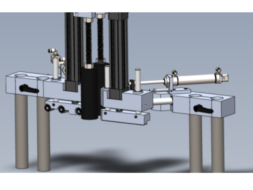
Details of bench assembly for saw clamps

Difficulté
Moyen
Durée
1 minute(s)
Introduction
Tools Required
Standard hex key set
Standard spanner set
External circlip pliers
20mm bearing dolly
Reduced shank 5mm hex key
Parts Required
B0000033 Linear Bearing: Ø20 x 30 Compact (Metal Case Only) x 8
B0000034 Linear Bearing: Ø16 x 30 Compact (Metal Case Only) x 8
B0000200 Circlip 8mm External x 12
B0000346 Ball Bearing 8 D 22 D 7 Long + seals x 6
D0004331 Clamp Head (D7450) x 1
D0004332 Clamp Mount Block (D7449) x 1
D0004333 Pillar x 2
D0004358 Clamp Head Bracket (D7447) x 1
D0004359 Clamp Head Cylinder Bar (D7446) x 2
D0004550 Clamp Insert x 2
D0004808 Slide Stop x 2
D0005191 Bearing Protective Washer x 4
D0005425 Clamp block Right (5625) x 1
D0005566 Clamp block left - Roller style (5567) x 1
D0005568 Clamp block left roller shaft x 3
D0007447 Clamp Head Bracket OH (D4358) x 1
D0007449 Clamp Mount Block OH (D4332) x 1
D0007450 Clamp Head OH (D4331) x 1
D0015266 Shaft 38.7mm: 440mm ZX Saw Top Clamp BZP x 2
D0015299 Shaft 16mm: 320mm Chip Deflector ZX5 x 1
D0015446B Chip Deflector Mounting Plate (Tapped) x 1
D0015447B Chip Deflector Probe Ø50 (Tapped) x 2
D0015454 Chip Deflector Rod (M16) x 2
H0004625 Shaft 16mm: 150 Saw Clamp x 2
H0004626 Shaft 16mm: 275 Eject Push x 1
H0004627 Shaft 20mm: 210 Saw Inner Clamp x 2
H0004628 Shaft 20mm: 245 Saw Outer clampx 2
M0001194 Kipp clamp handle x 2
P0000007 Straight Adaptor 6mm - 1/8 BSP tapered thread x 1
P0000054 Cylinder Ø32 x 50 (PIS32A50) x 1
P0000064 Pneumax microcylinder 25bore x 80stroke x 2
P0000295 Elbow Adaptor 6mm - 1/8 BSPT (Metal type) x 3
P0001143 cylinder 32 x 175mm stroke ISO x 1Étape 1 - Unless otherwise stated
All bolts to have Loctite 243 adhesive applied unless otherwise stated
All Threaded Pneumatic connections to have Loctite 570 applied
All bolts to be pen marked once adhesive applied and correct tension added

Étape 2 - Fit clamp heads to clamp mount blocks
Slide assemblies together as shown
Tare care not to damage bearing seals
Remove excess grease from shafts once installed
Once fitted, check movement is free and consistent


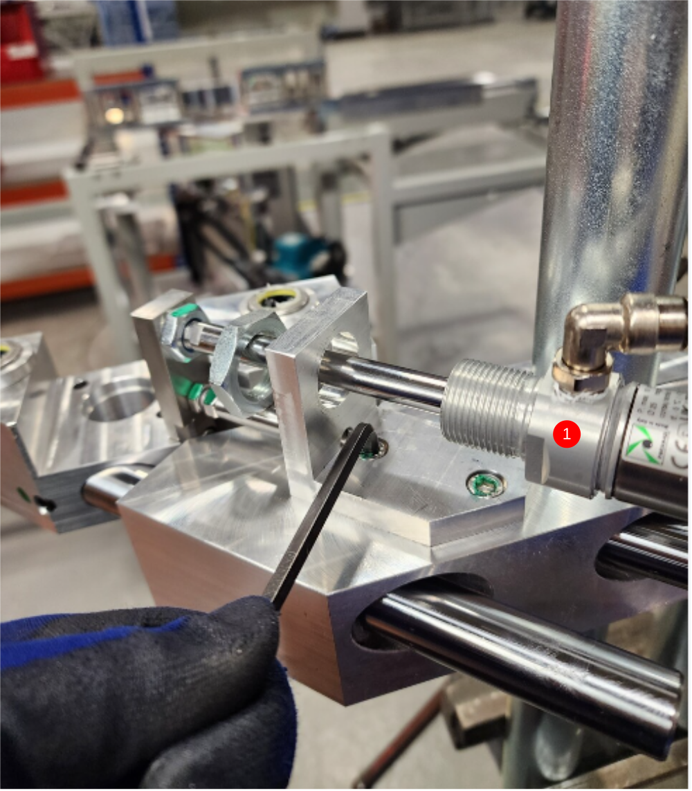
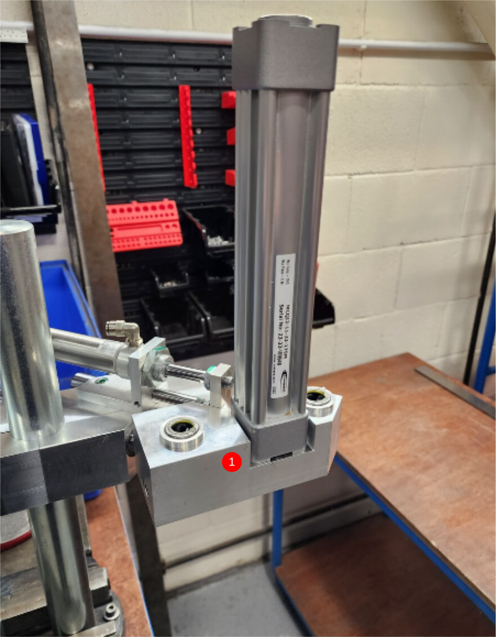
Étape 3 - Fit cylinder and align
1 Fit hard stop assembly to clamp head. Use 2 off M6 x 16 socket caps to fix ,only apply light tension to this bolt to allow adjustment
2 Fit cylinder to hard stop bracket and attached cylinder piston to mounting plate , do not apply adhesive on either
3 Contract cylinder and tension all fixing points
Ensure clamp movement is smooth and consistent with all fasteners tight


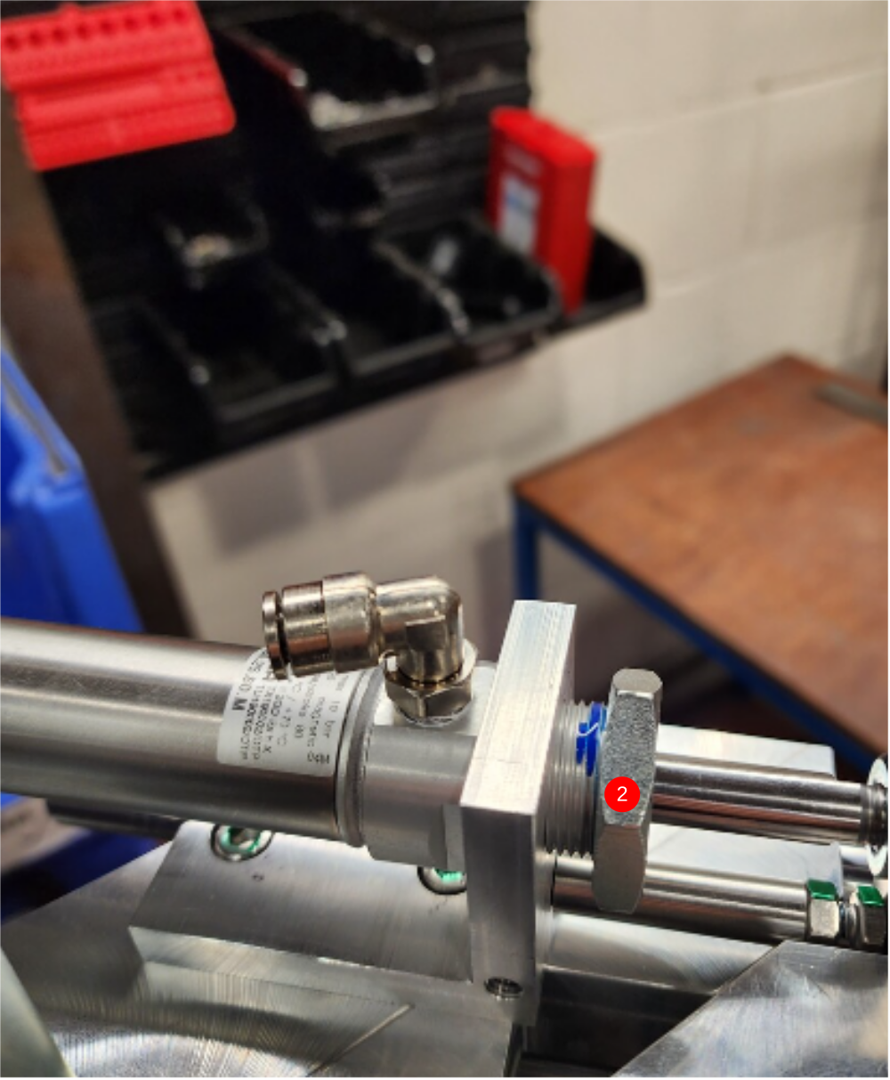
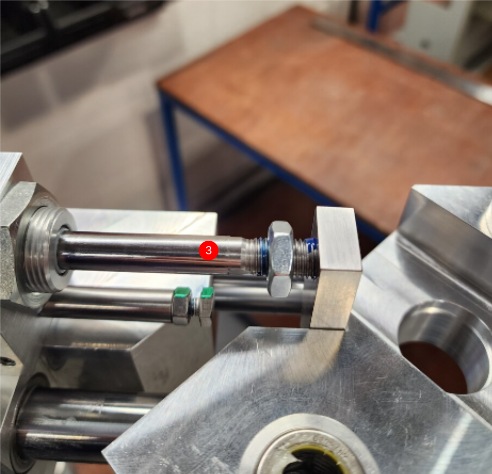
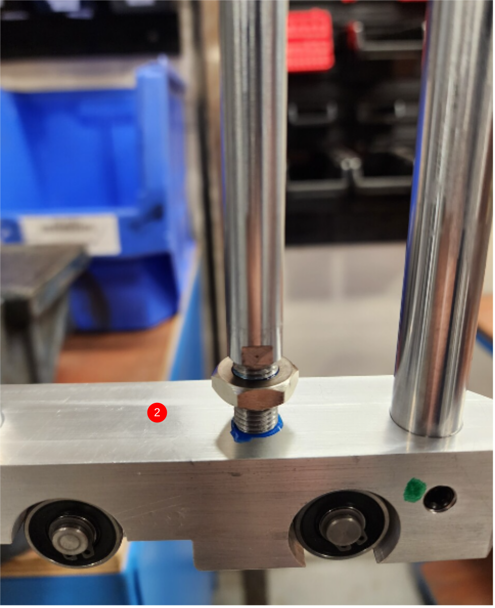
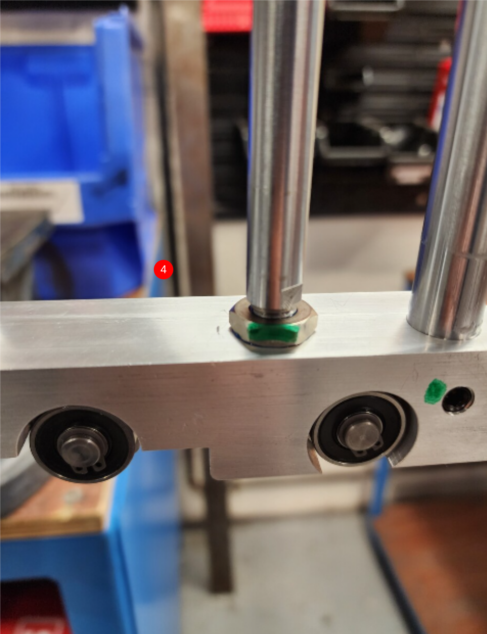
Étape 4 - Finalise cylinder
Once alignment is achieved, fasteners must be finalised
1 Remove cylinder 32mm locknut an pull cylinder back. This gives access to 2 off M6 socket caps to finalise individually
2 Refit 32mm locknut applying adhesive to thread and finalise
3 Retract cylinder thread and nut, apply adhesive and finalise
Repeat for other clamp assembly
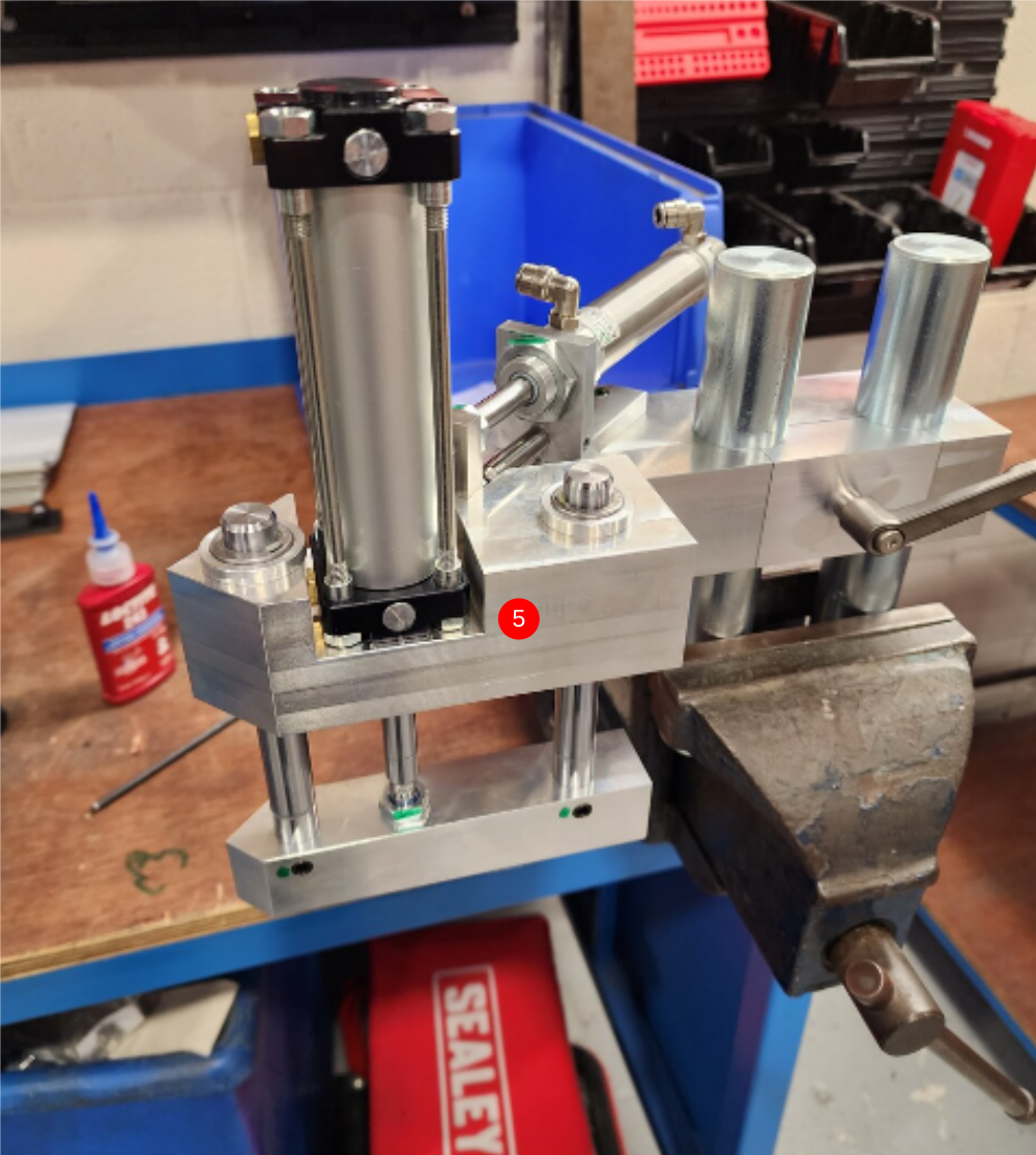
Étape 5 - Fit clamp blocks
1 Attach large cylinder to infeed clamp assembly using 2 of M6 x 35 socket caps , apply adhesive but only light tension
2 Insert pre built roller clamp assembly. Take care to not damage bearing seals when fitting shaft ,Apply adhesive to cylinder thread and wind into clamp block
3 Ensure cylinder is contracted and tension M10 cylinder nut and 2 off m6 socket caps to set alignment. Check movement is even and no tight spots are evident at ends of cylinder stroke
4 Finalise all fasteners
5 Repeat for Eject clamp side using 2 off M6 x 30 socket caps to fix shorted cylinder
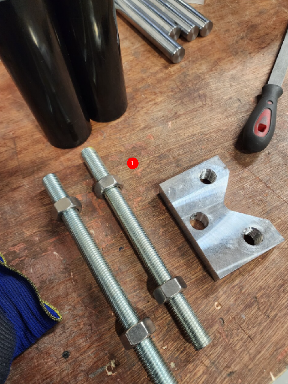
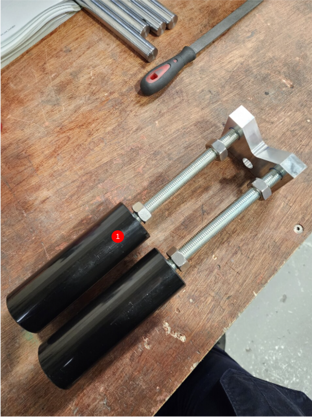
Étape 6 - Assemble Deflector Probes
1 Assemble deflector probes as shown
2 Attach to infeed clamp assembly using Dry M8 x 20 kcp grubscrew
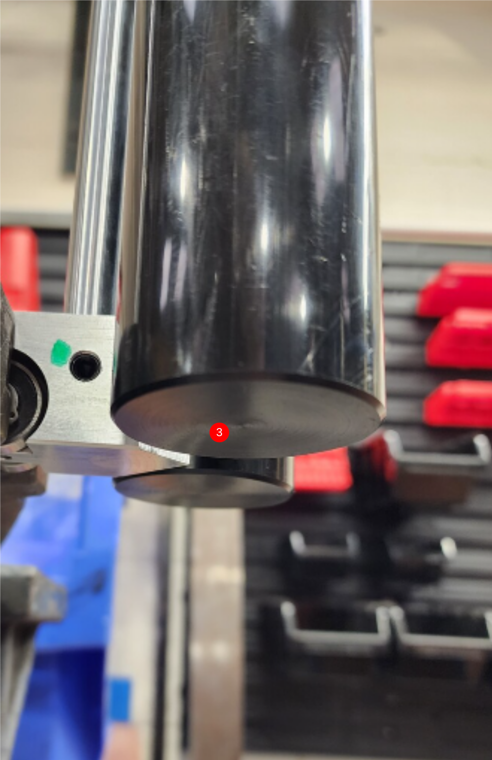
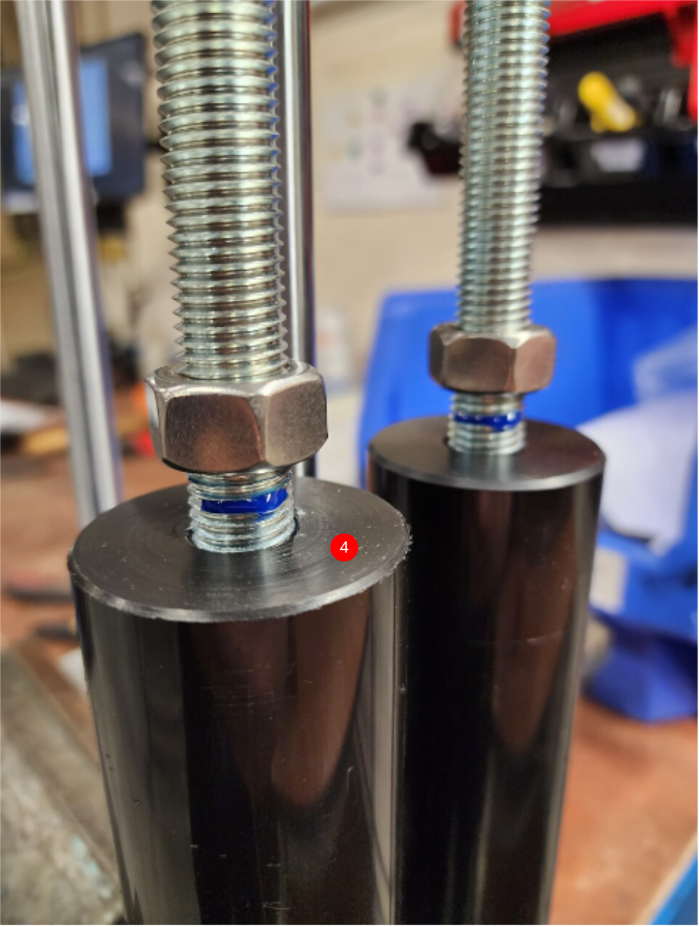
3 Adjust length of probes to be 1mm Above bottom of clamp block
4 Apply adhesive and lock off and finalise all M16 nuts
5 Remove assembly from clamps
Draft
 Français
 English
 Deutsch
 Español
 Italiano
 Português