Assembly instructions

Difficulté
Moyen
Durée
2.5 heure(s)
Sommaire
- 1 Introduction
- 2 Étape 1 - Unless otherwise stated
- 3 Étape 2 - Flow regulator setting
- 4 Étape 3 - Assemble Valve Bank
- 5 Étape 4 - Updated position of air fittings on push eject cylinders
- 6 Étape 5 - Warning
- 7 Étape 6 - Assemble push eject
- 8 Étape 7 - Finalise cylinders
- 9 Étape 8 - Fit grease points and grease
- 10 Étape 9 - Fit reed switches to 1 off push eject
- 11 Fit to 1 cylinder only
Introduction
Tools Required
Standard Hex Key set
Standard spanner set
Standard screwdriver set
Bearing press
Test box for cylinder switch function
Parts Required
B0000034 Linear Bearing: Ø16 x 30 Compact (Metal Case Only) x 8
B0000236 90 Deg Grease Nipple M6 ST/ST x 4
D0004311 Side Eject Block x 2
D0004591 Side Eject Housing x 2
D0004592 Eject Housing Plate x 2
D0005200 Safety Dead Stop Block x 1
D0005201 Safety Dead Stop Backer (5357) x 1
D0005202 Safety Dead stop Yoke (5358) x 1
D0005203 Safety Slider Cap x 2
H0004626 Shaft 16mm: 275 Eject Push x 4
M0000101 Compression Spring 11 D 15 D 25 Long x 1
P0000035 Cylinder 25x160 x 2
P0000174 Fitting: Plug 1/4'' BSP (Grubscrew Type x 2
P0000201 Flow Controller 6mm x M5 Elbow x 2
P0000367 16mm bore X 125 stroke with rod end clevis x 1
P0000369 Clamp to suit P0000367 x 2
P0000327 Reed Switch: Pneumax 1580U (5.0m Lead) x 2
P0001068 Valve Base: Type 41 2 Position Ø6 x 1
P0001085 Fitting: SMC 1/4" to Ø8 Swivel Elbow x 1
P0001163 1/4 bsp male silencer x 2
P0001186 Valve/ 5/2 smc x 2
P0001198 1/8 bsp 6mm speed controller x 4
P0000394 reed switch holder x 2
P0000444 Reed switch pneumax x 2Étape 1 - Unless otherwise stated
Use Loctite 243 on all fasteners
Use Loctite 570 on all threaded pneumatic connections
Pen mark all bolts when finalised

Étape 2 - Flow regulator setting
All flow regulator fittings should be set to the following
Adjust to the fully closed position (clockwise rotation)
Adjust back 2.5 turns (anti clockwise)
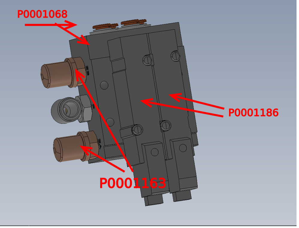
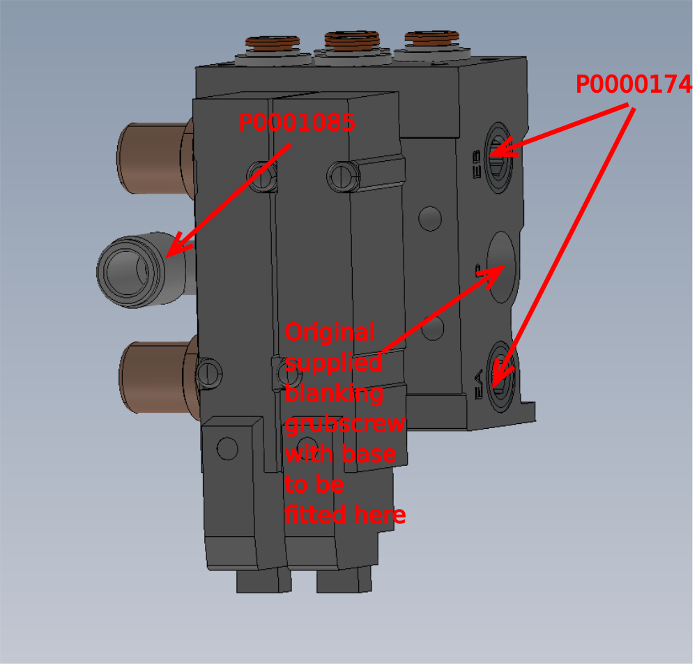
Étape 3 - Assemble Valve Bank
Assemble valve bank orientated as shown
Use parts
P0001068 Valve Base: Type 41 2 Position Ø6 x 1
P0000174 Fitting: Plug 1/4'' BSP (Grubscrew Type x 2
P0001085 Fitting: SMC 1/4" to Ø8 Swivel Elbow x 1
P0001186 Valve/ 5/2 smc x 2
P0001163 1/4 bsp male silencer x 2
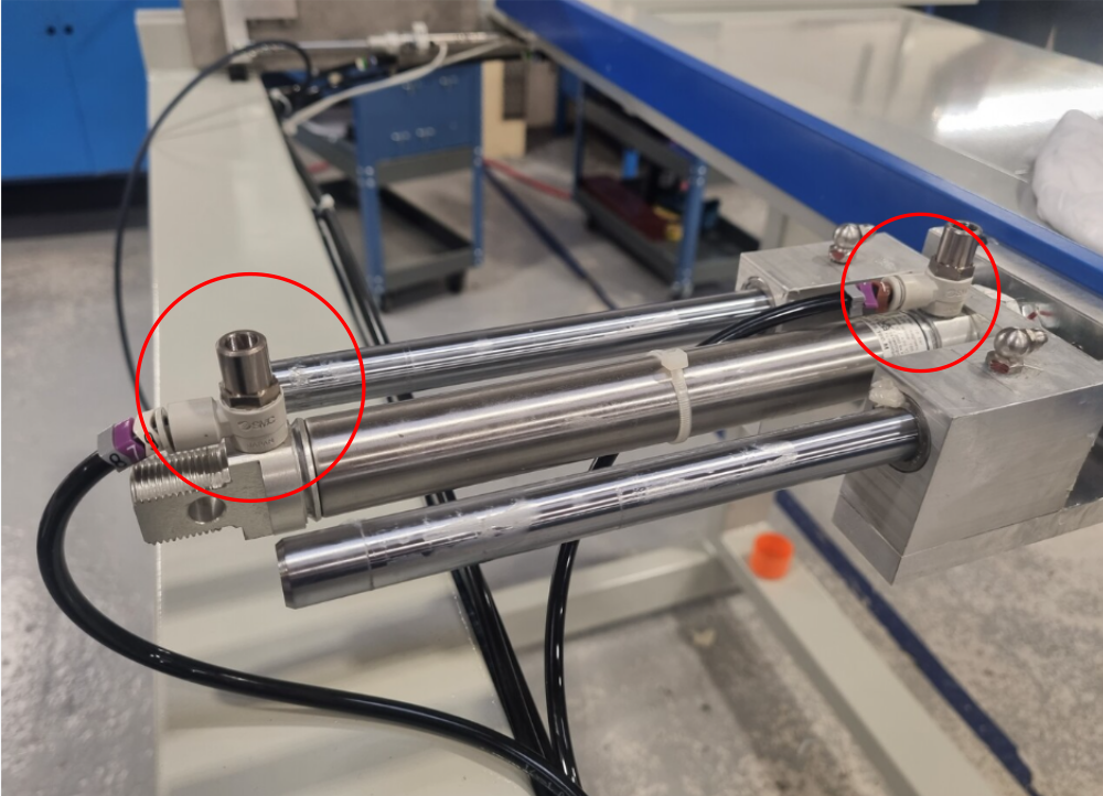
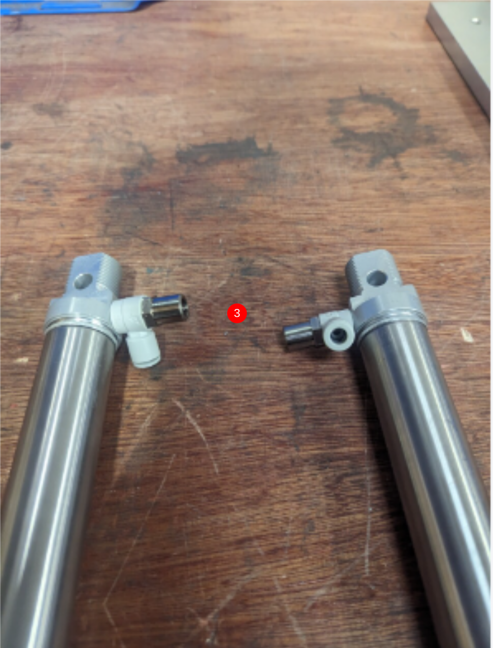
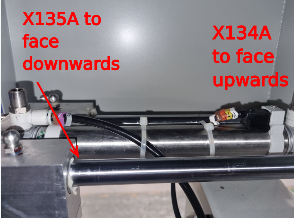
Étape 4 - Updated position of air fittings on push eject cylinders
Air fitting position has been updated on the push eject assemblies
Air fittings now face the top as shown
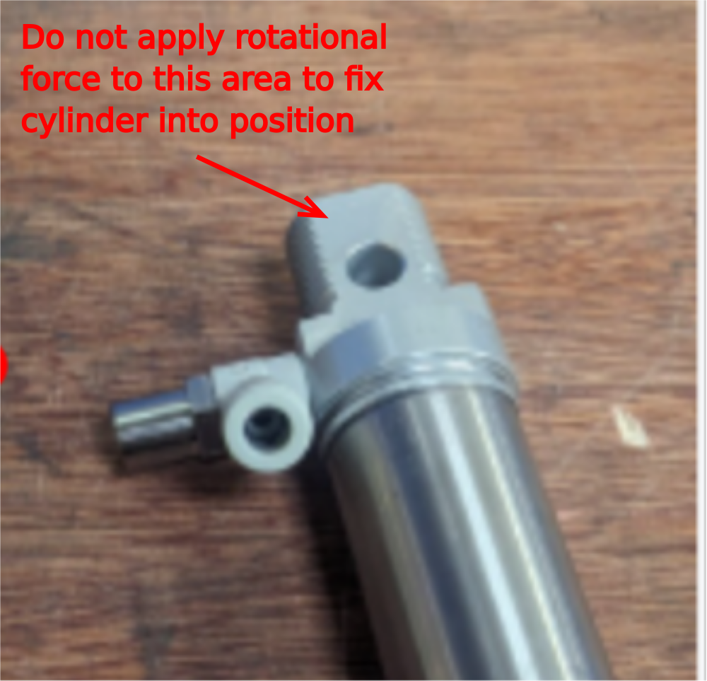
Étape 5 - Warning
Please note that the area indicated on cylinders is not to be used to tension cylinders when fixing. If this area is used to add rotational force when fitting it will cause the cylinder to fail

Étape 6 - Assemble push eject
1 Updated photos for cylinder air fitting required. Ports now face top!
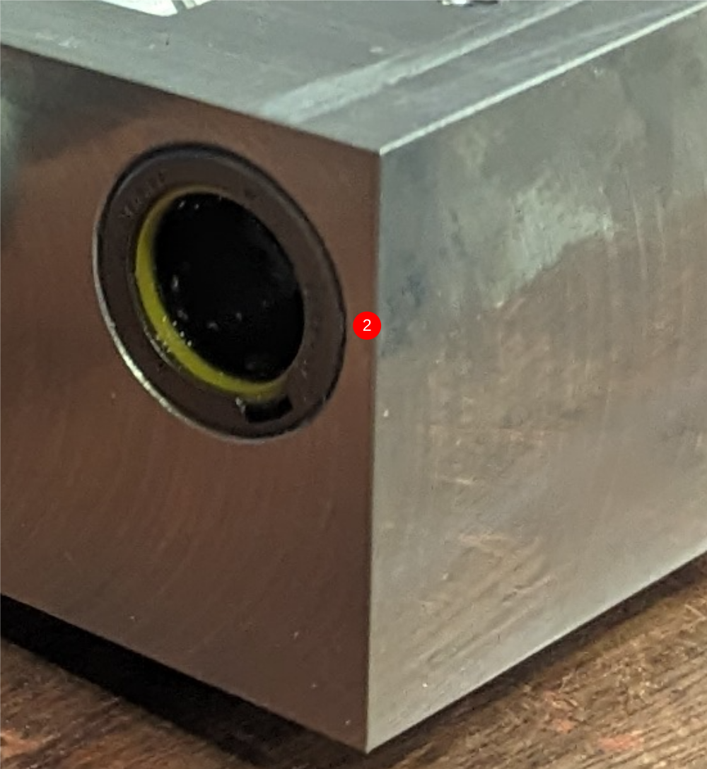
2 Fit B0000034 Linear Bearing 8 off into D0004591 Side Eject Housing using the beasring press. Ensure yellow seal of bearing faces outwards as shown
3 Attach 4 off P0001198 1/8 bsp 6mm speed controller to P0000035 Cylinder 25x160 2 off as shown
4 Fit assembled cylinder to bearing block orientated as indicated , and apply adhesive to large locking nut but do not tension
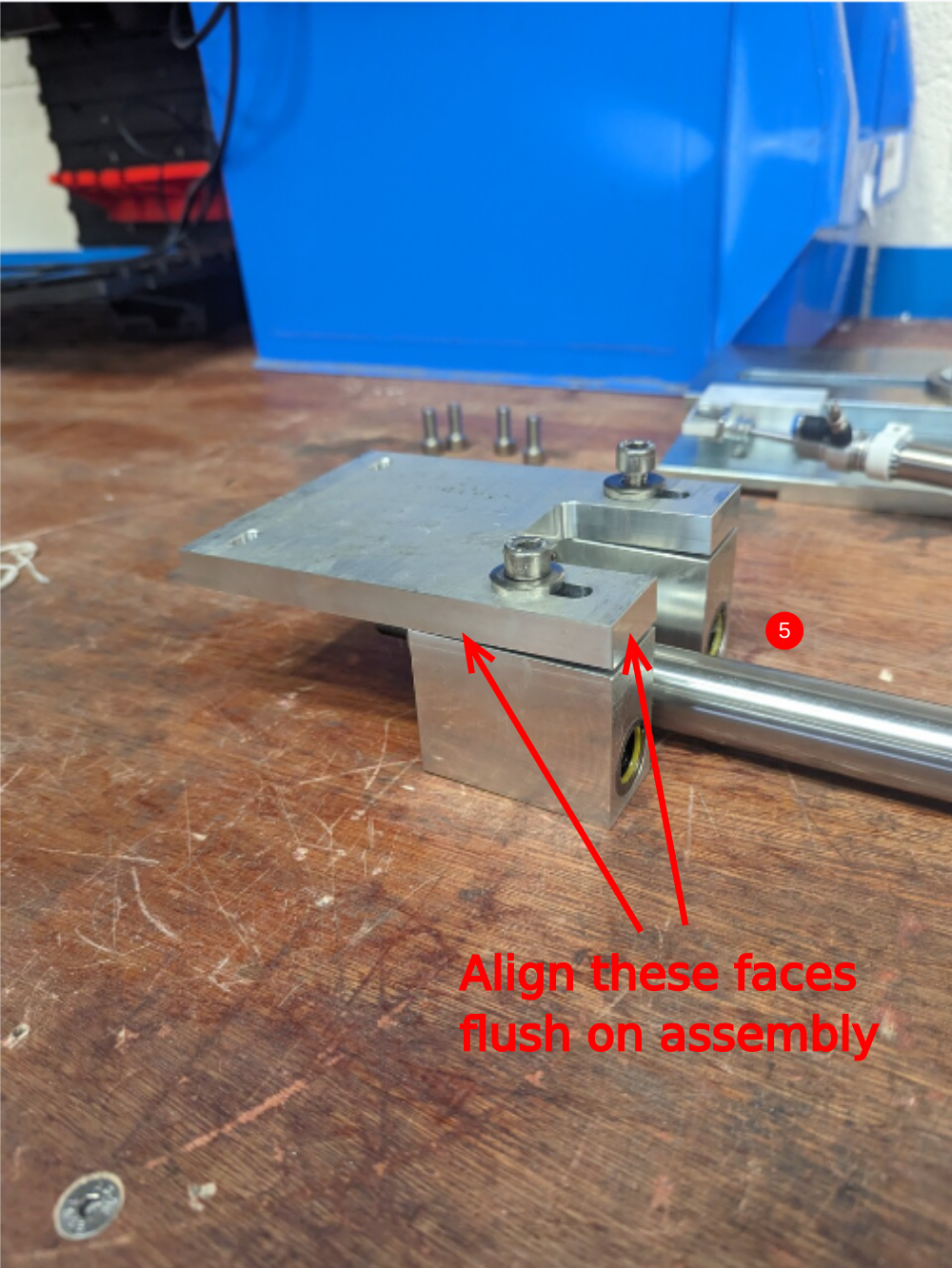
5 Fit D0004592 Eject Housing Plate and secure with M8 x 30 socket caps and Heavy M8 washers . Ensure these bolts are glued and tensioned correctly.
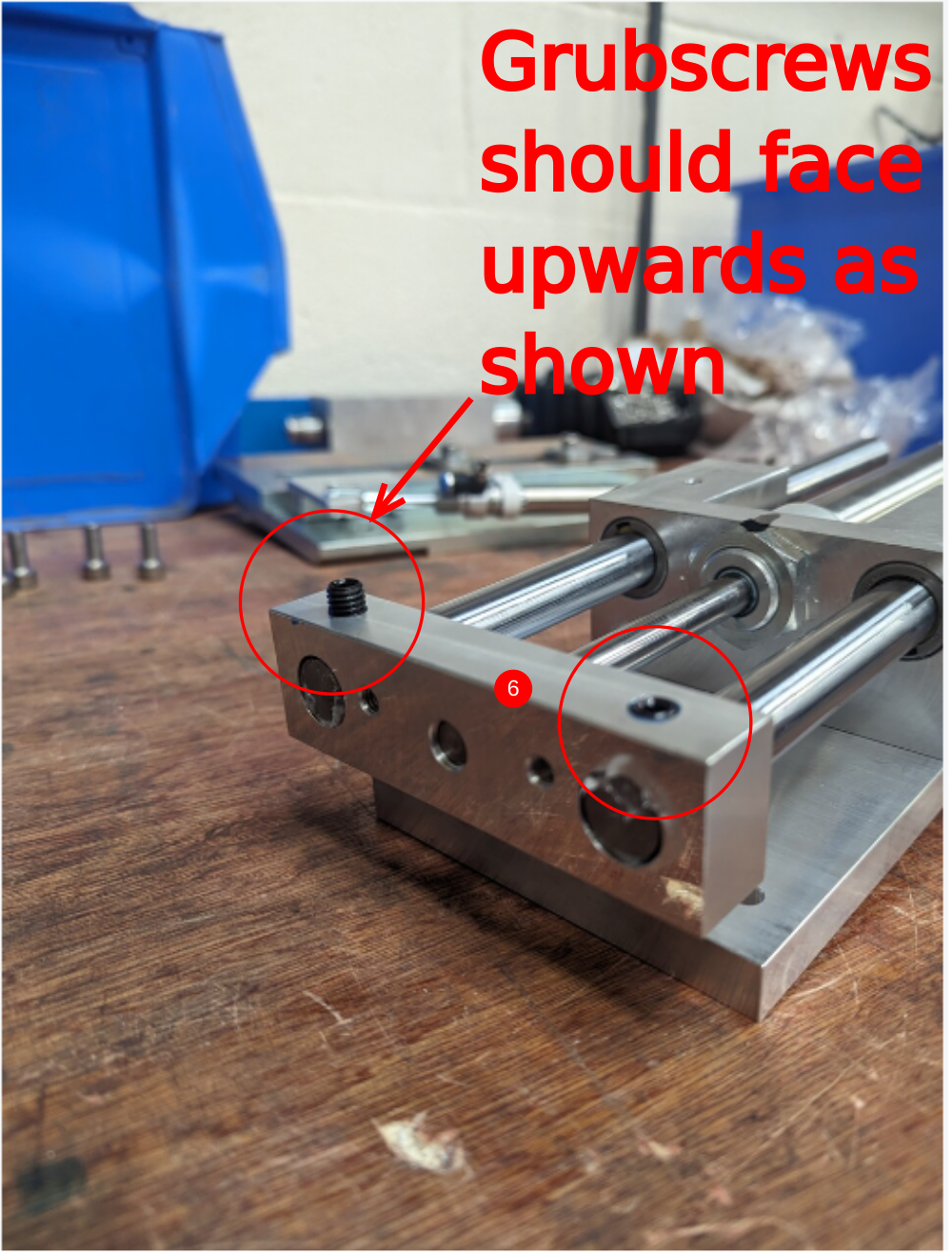
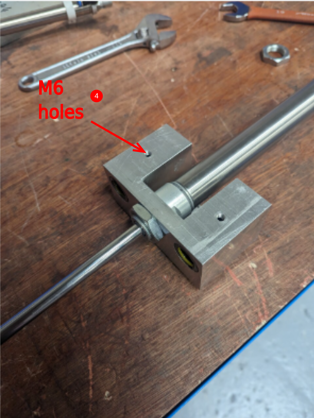
6 Insert 4 off H0004626 Shaft 16mm: 275 and fit 2 off D0004311 Side Eject Block orientated as shown. Wind in cylinder piston into eject block ,then Secure shafts by aligning dimples and securing with m8 x 12 kcp grubscrews
Étape 7 - Finalise cylinders
Updated photos for cylinder air fitting required. Ports now face top!
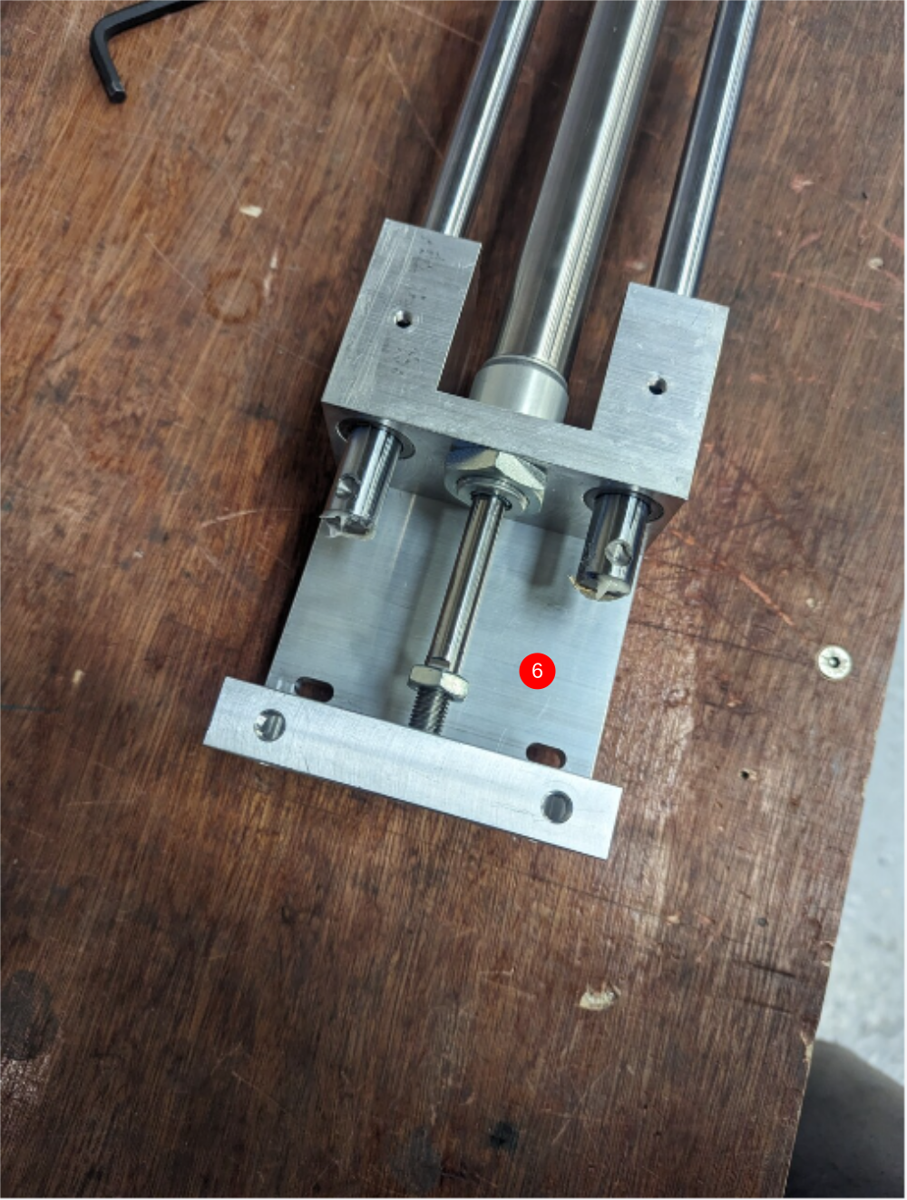
Finalise 32mm nut and 17mm nut on cylinders.
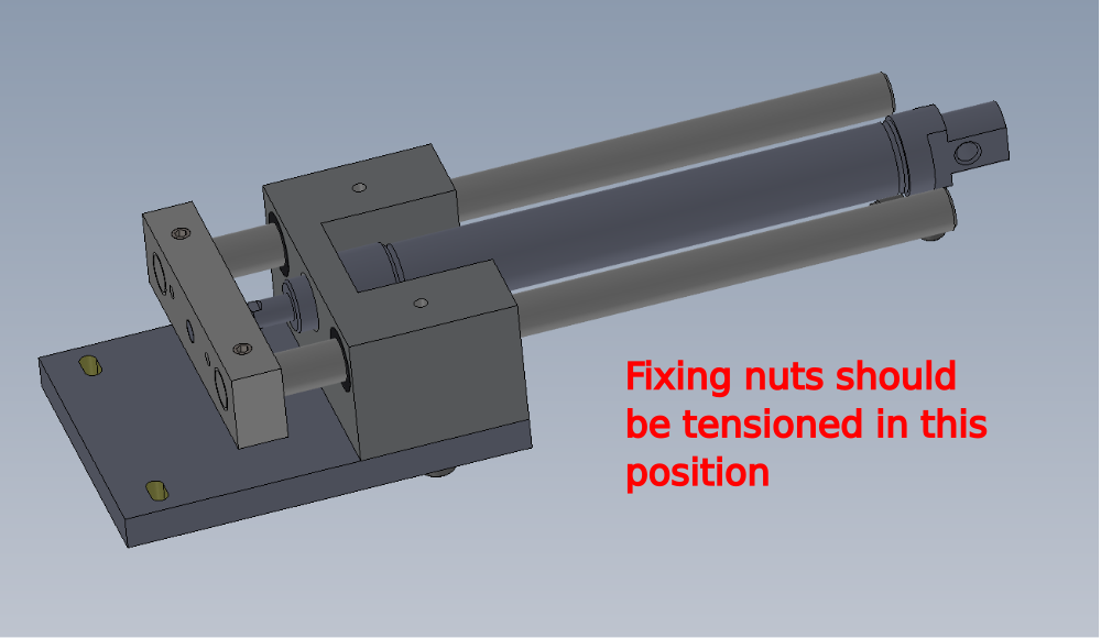
Ensure both nuts are tightened when the cylinder is the closed position, to aid alignment
To apply final tension to 32mm nut, it may be required to remove 1 off hardened shaft to allow correct access for tensioning nut
Once all fixings are tensioned correctly, cylinder stroke travel should be smooth and consistent at all points of travel. No tight spots should be present at any area.
Étape 8 - Fit grease points and grease
Updated photos for cylinder air fitting required. Ports now face top!
Fit 4 off B0000236 90 Deg Grease Nipple M6 as indicated ( 2 per assembly)
Use grease gun to apply grease to assemblies

Étape 9 - Fit reed switches to 1 off push eject
Fit to 1 cylinder only
Add identification markers to 2 off P0000327 Reed switch pneumax
Label as X134A and X135A
Use P0000394 reed switch holder to secure to cylinder, orientate as shown
Make sure these sensors are not overtightened when fitting. Once secured, use tester to box to check that the activate and deactivate.
Dokit link for upgrade Guide_to_Fitting_Eject_Push_Sensors_on_ZX_Machines
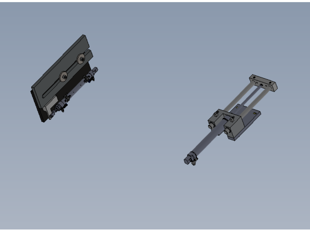
Étape 10 - Assemble Safety gate cylinder
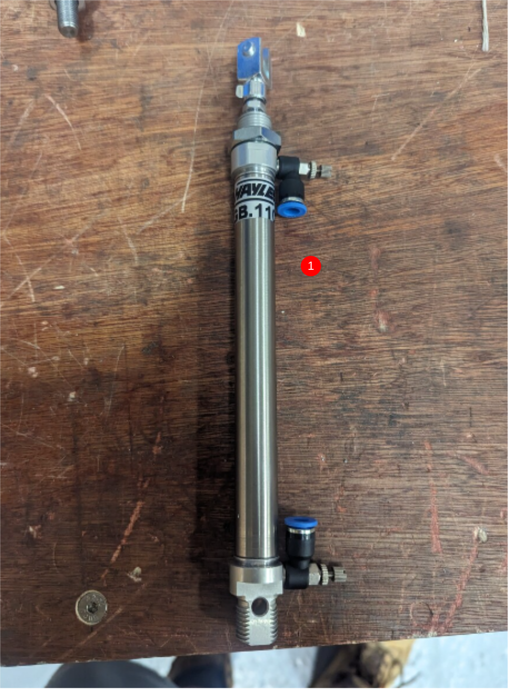
1 Fit 2 off P0000201 Flow Controller 6mm x M5 Elbow as shown
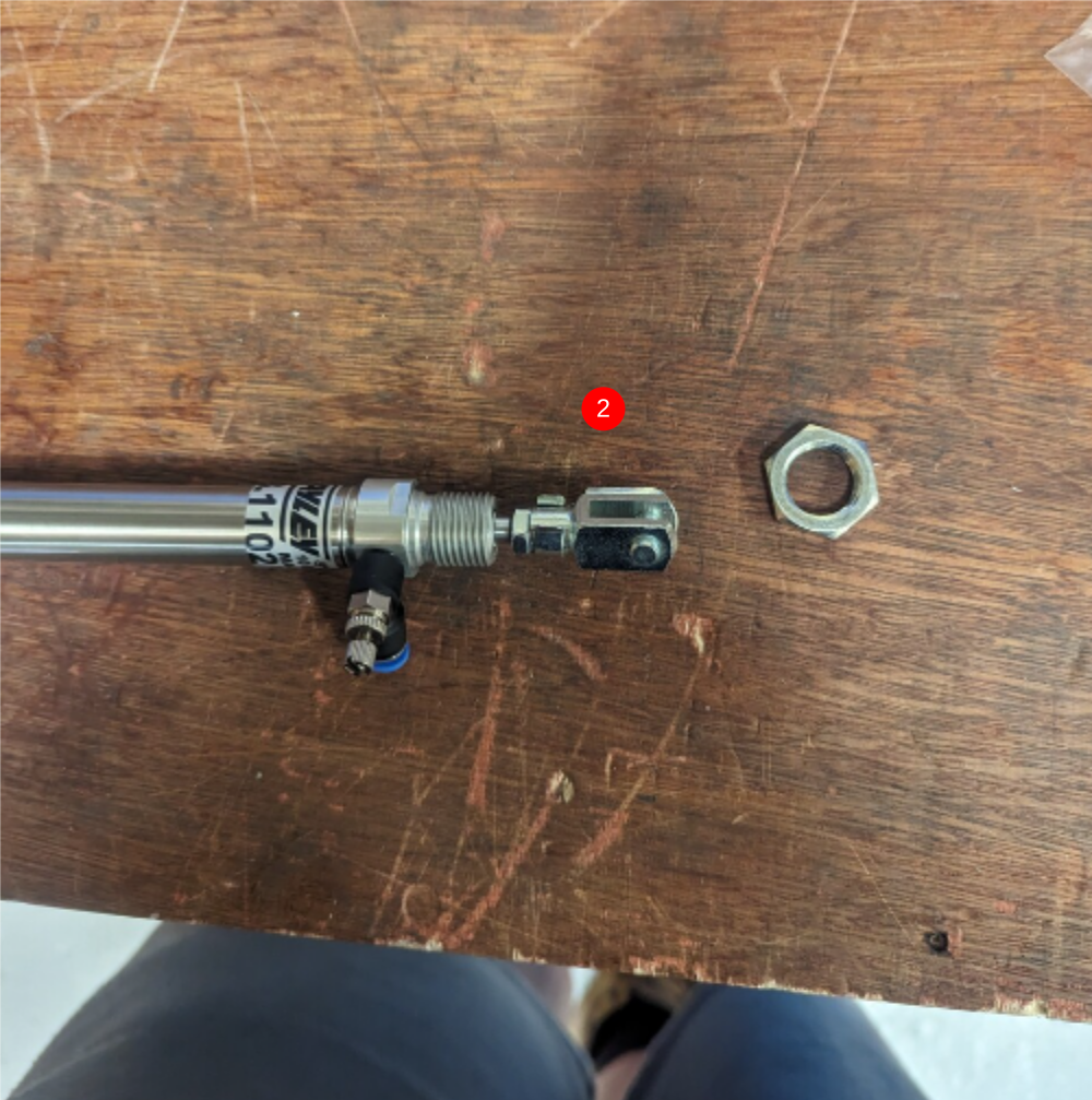
2 Remove fixing nut shown as not required
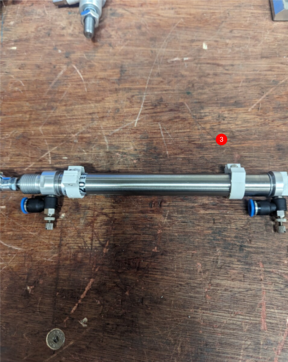
3 Fit 2 off P0000369 reed switch clamp as shown. Make sure these sensors are not overtightened when fitting. Once secured, use tester to box to check that the activate and deactivate.
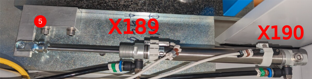
4 Identify using markers 2 off P0000444 reed switches as X189 and X190
5 Fit P0000444 switches as shown . X190 goes to base, X189 goes to nose of cylinder. Use test box to accurately set and check function of reed switches
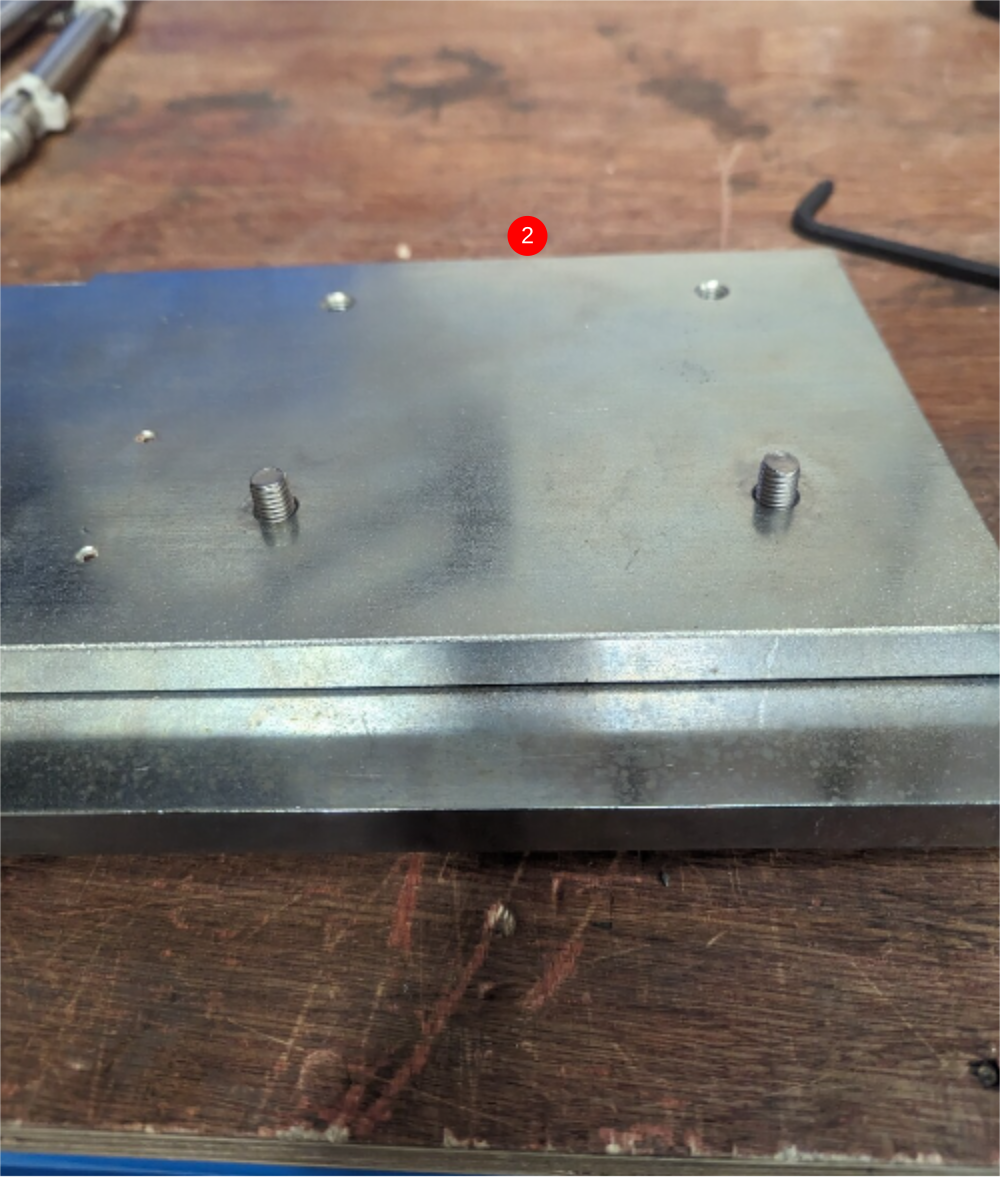
Étape 11 - Assemble safety gate
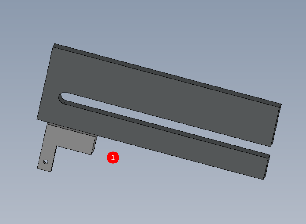
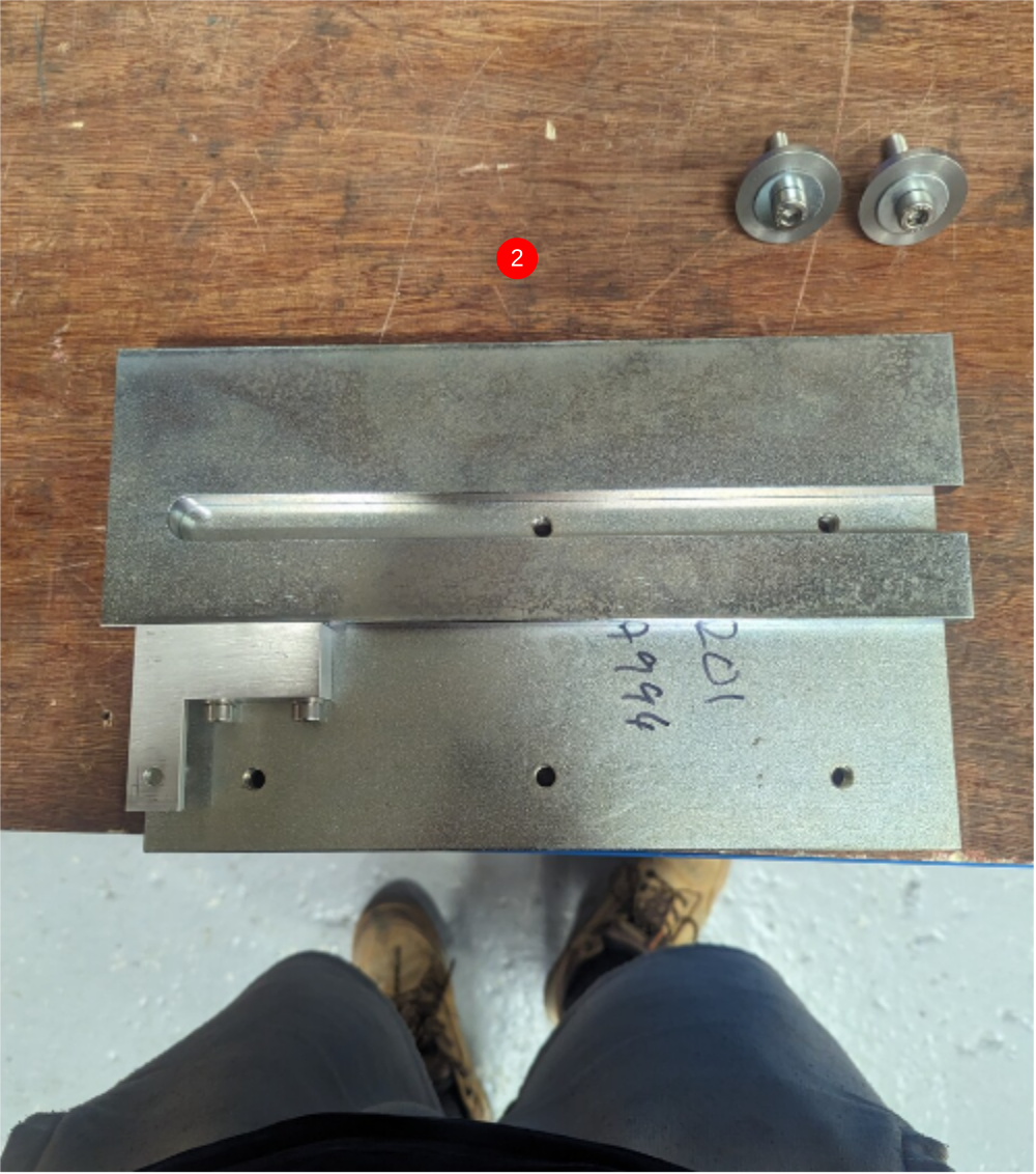
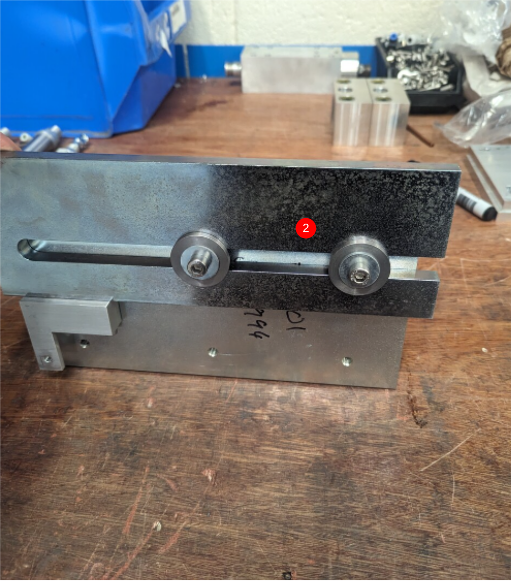
1 Attach D0005202 Safety Dead stop Yoke to D0005200 Safety Dead Stop Block as shown using M6 x 35 cap heads and A form washers
2 Attach dead stop block to D0005201 Safety Dead Stop Backer using D0005203 Safety Slider Cap 2 off. Fix as shown using M8 x 50 socket caps M8 penny washers and backed off with a M8 nyloc nut and M8 washer as shown3
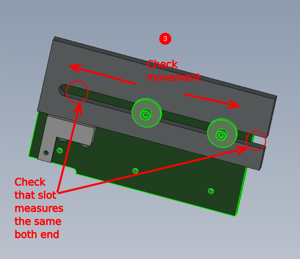
3 Ensure part moves freely in the direction shown
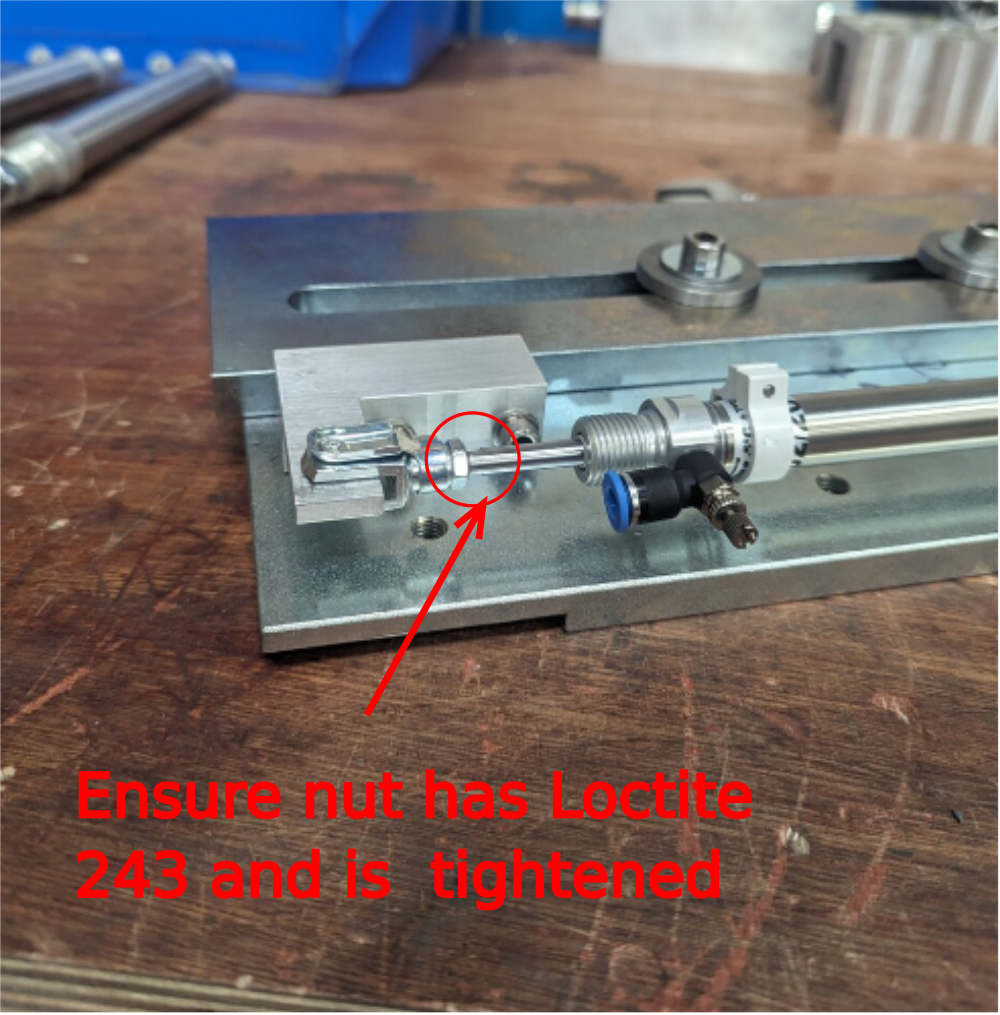
Étape 12 - Attach cylinder
Attach pre assembled cylinder as shown
Ensure indicated nut is glued and tight
Draft
 Français
 English
 Deutsch
 Español
 Italiano
 Português