2nd stage of assembly of spindle assemblies


Difficulté
Moyen
Durée
4 heure(s)
Sommaire
- 1 Introduction
- 2 Étape 1 - Unless otherwise stated
- 3 Étape 2 - Important Information
- 4 Étape 3 - Adjustable P bracket only Mount single plunge spindle cylinder 2,4,6 and 8
- 5 Étape 4 - Adjustable P Bracket only Align components and set position
- 6 Étape 5 - Fixed P bracket only Mount single plunge spindle cylinder 2,4,6 and 8 Adjustable P bracket
- 7 Étape 6 - Check D0007649
- 8 Étape 7 - Adjustable P Bracket only Mount double plunge spindle cylinder 1,3,5 and 7
- 9 Étape 8 - Adjustable P Bracket only Align components and set position
- 10 Étape 9 - Fixed P Bracket only Mount double plunge spindle cylinder 1,3,5 and 7
- 11 Étape 10 - Adjustable P Bracket only Attach single plunge motor plate
- 12 Étape 11 - Fixed P Bracket only Attach single plunge motor plate
- 13 Étape 12 - Double plunge assembly motor mount
- 14 Étape 13 - Mounting double plunge motor
- 15 Étape 14 - Mount double plunge cylinder
- 16 Étape 15 - Mount hard stops
- 17 Commentaires
Introduction
Tools Required
0.05mm feeler gauge
Standard hex key set
Standard spanner set
Rule
6mm punch
Ball pien hammer
Parts Required
D0007990 cylinder anchor x 7
D0007648 end plate x 4
D0007649 Double slide end plate x 4
D0007686 single motor plate x 4
D0007723 Double slide motor mount x 4
D0007687 Motor mount x 4
D0007600 Cylinder anchor x 4
D0015856 hard stop x 4
Étape 1 - Unless otherwise stated
Use Loctite 243 on all fasteners
Pen mark bolts when finalised

Étape 2 - Important Information
This instruction covers the fitting of 2 different styles of cylinder P bracket sets
Please see photos for clarity on differences
Steps will detail if any specific settings are required for the appropriate style of P bracket being fitted


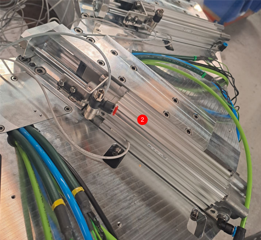
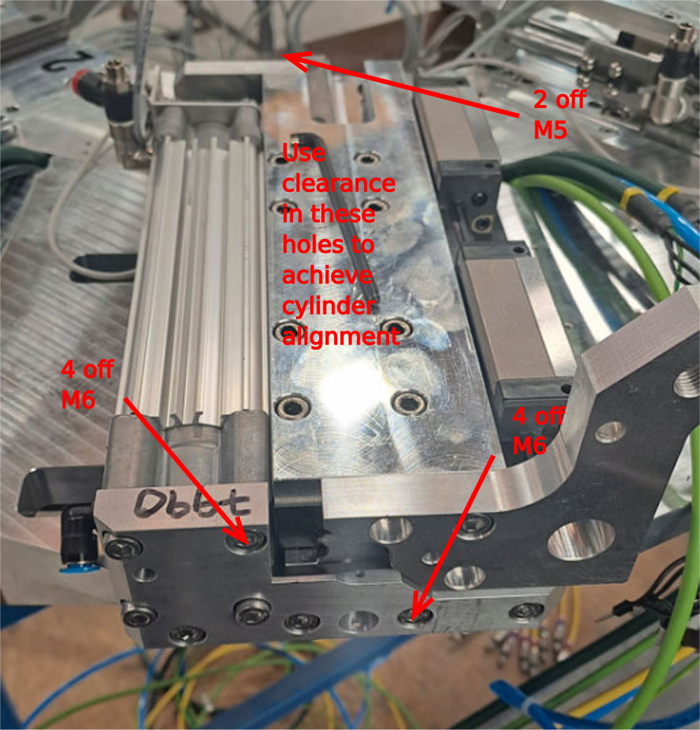
Étape 3 - Adjustable P bracket only Mount single plunge spindle cylinder 2,4,6 and 8
Adjustable P bracket only
Do not add final tension to bolts until alignment has been achieved
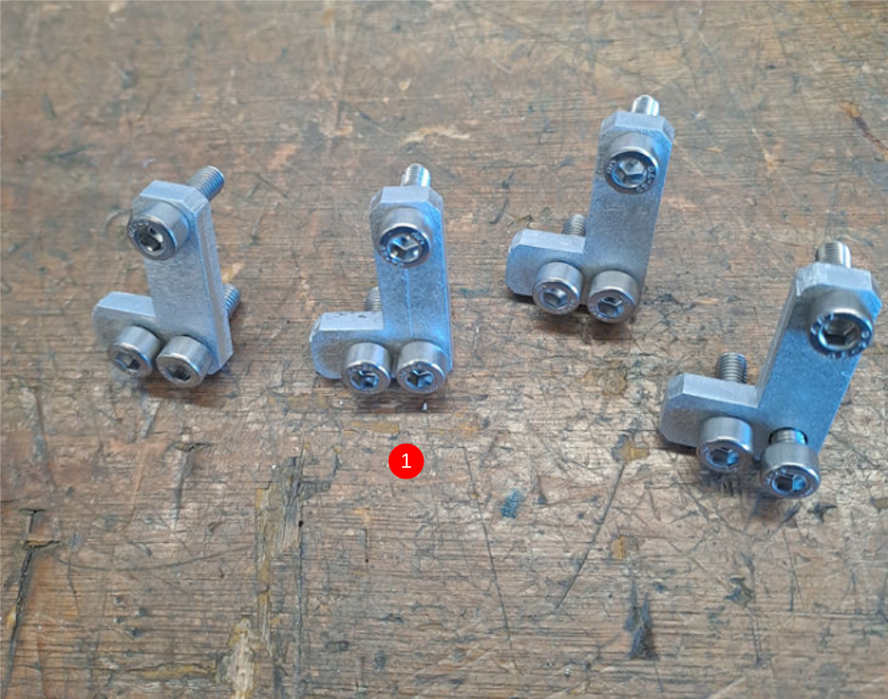
1 Attach pre built cylinder anchor to end of cylinder
2 Position pre built cylinder on slide base assembly as shown
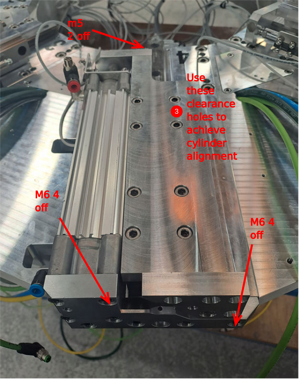
3 Use 2 off m5 x 25 socket caps with A form washers to attach to slide base
4 Temporarily mount D0007648 with 1 off m6 x 20 socket cap
5 Attach D0007790 cylinder anchor with 4 off M6 x 20 socket caps
6 Attach Cylinder base to anchor with 4 off M6x 20 socket caps
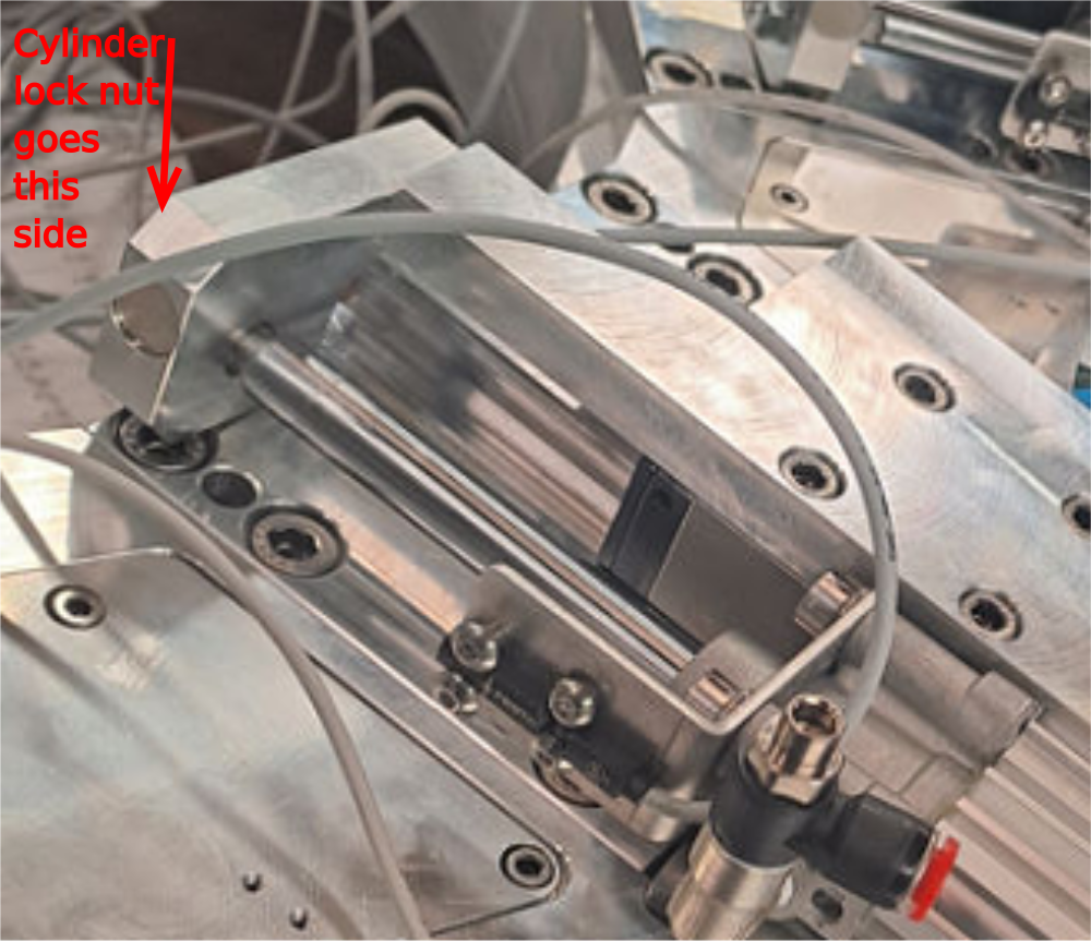
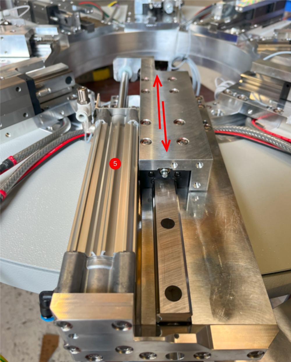
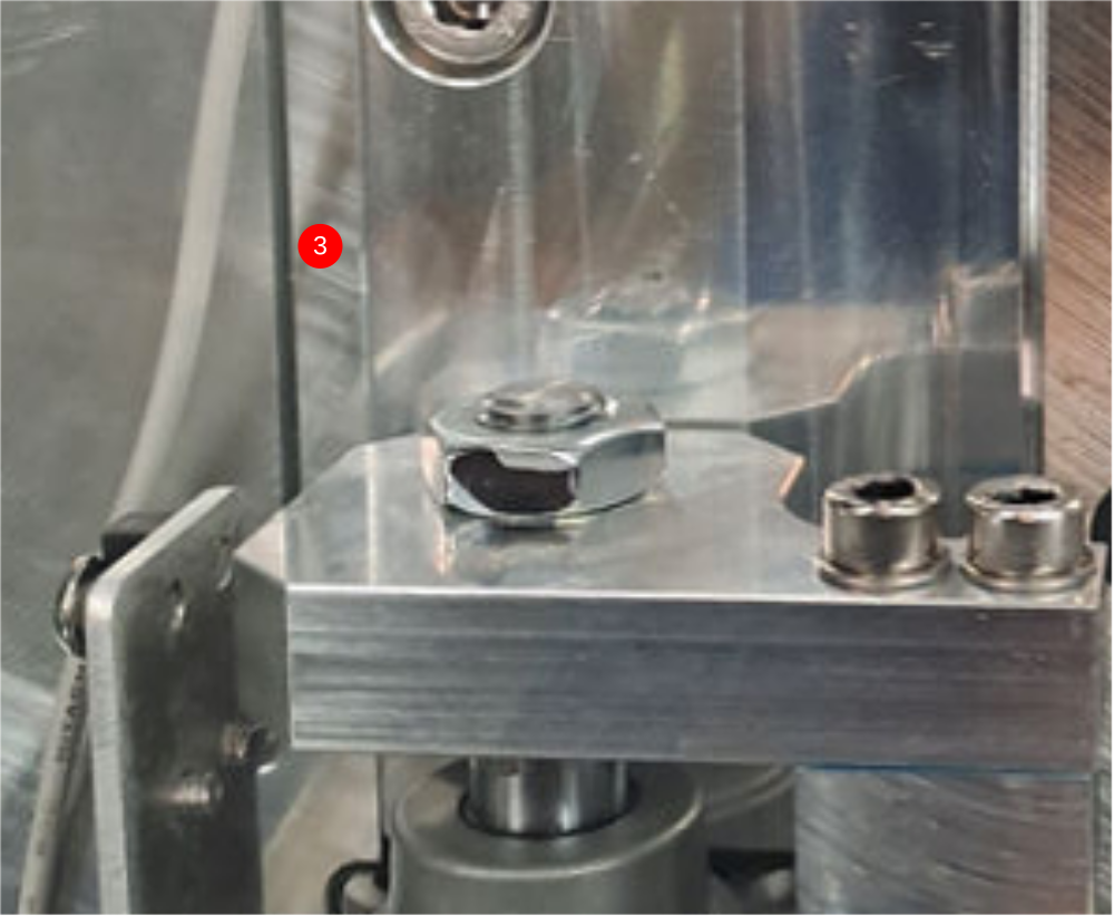
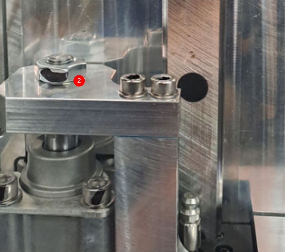
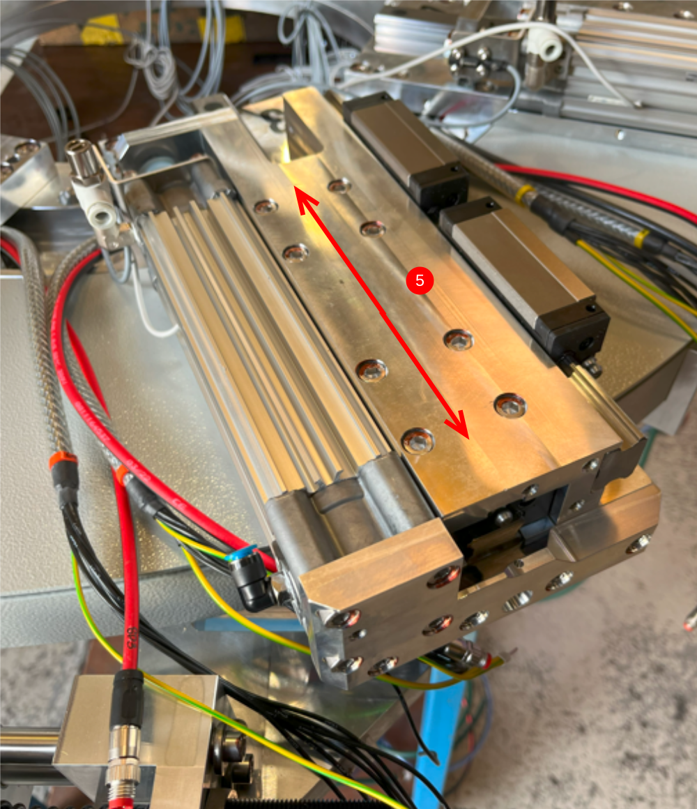
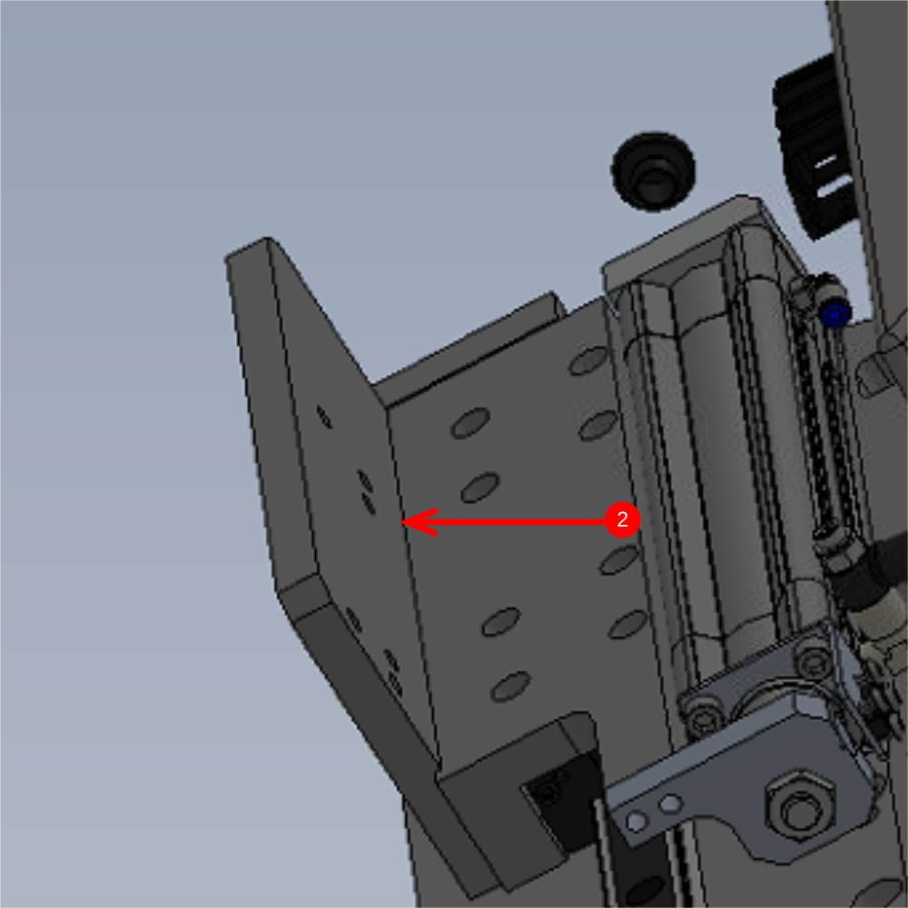
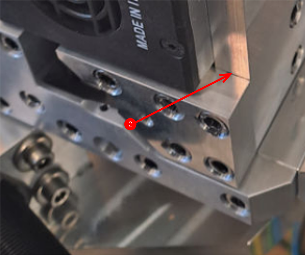
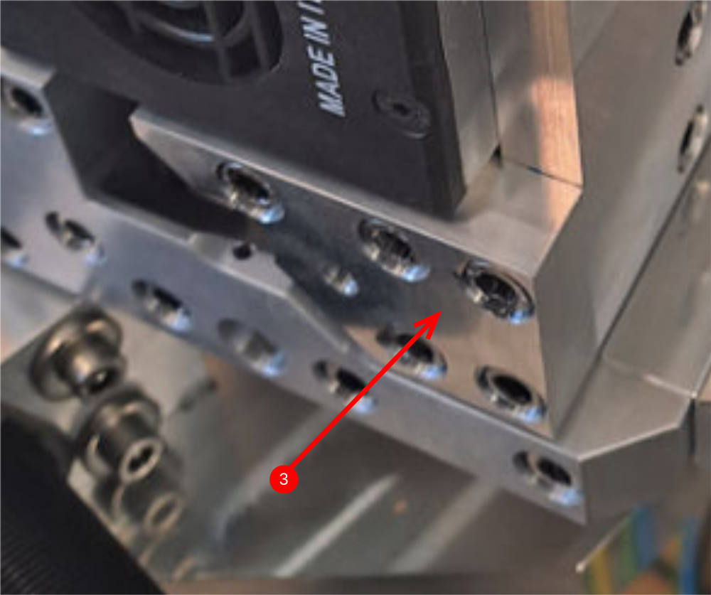
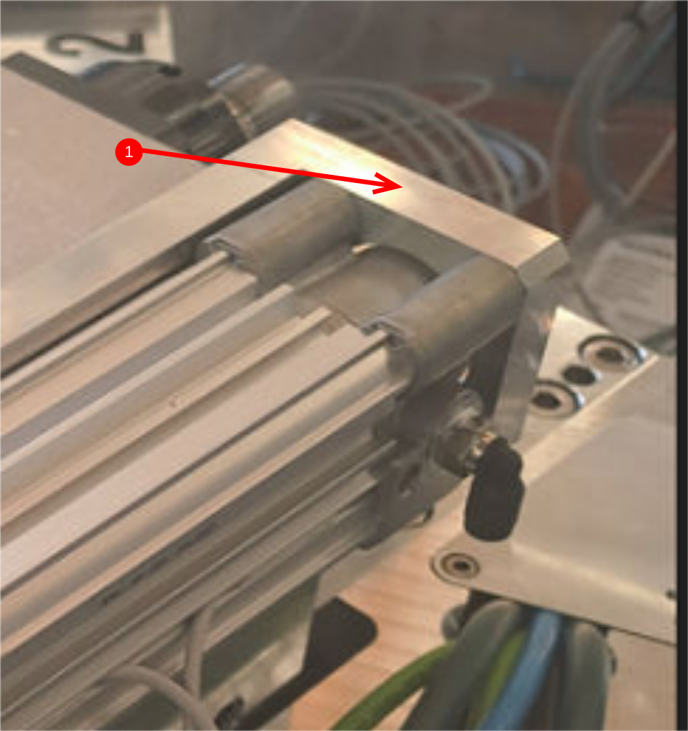
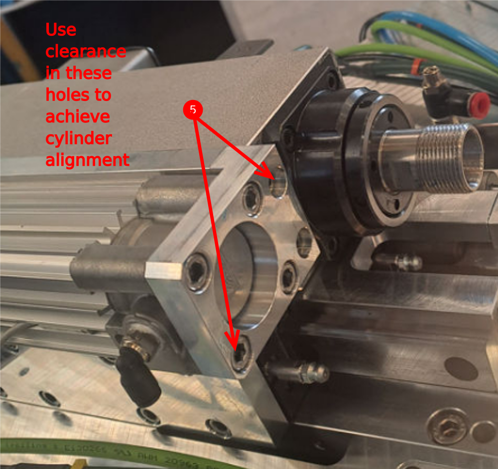
Étape 4 - Adjustable P Bracket only Align components and set position
Adjustable P Bracket only
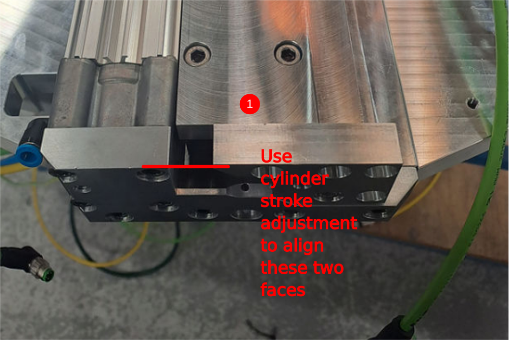
1 Use cylinder stroke adjustment to align these two faces
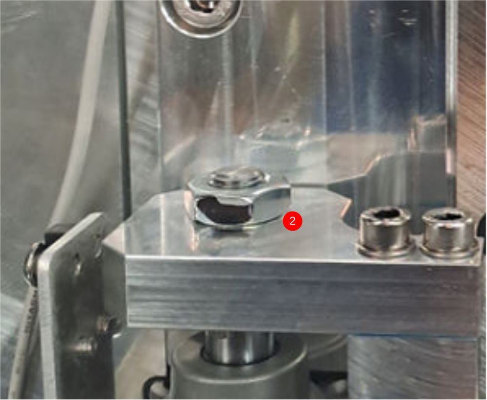
2 Apply Loctite 243 to cylinder nut and tighten
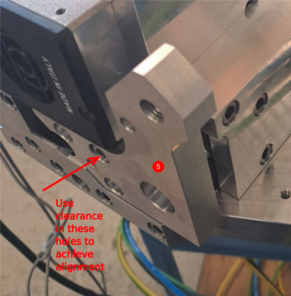
3 Use clearance in holes for mounting at points indicated to achieve cylinder alignment. Cylinder stroke should be even and free along entire stroke
4 Finalise bolts
Repeat on all four single spindles (2,4,6 and 8)
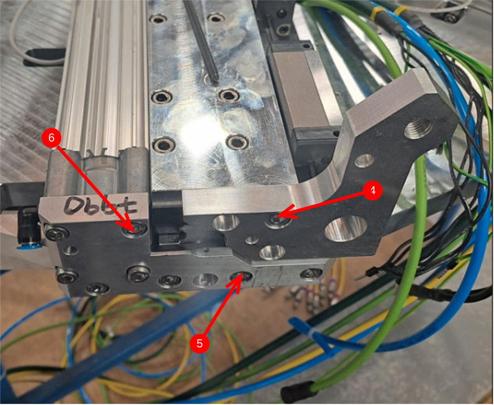
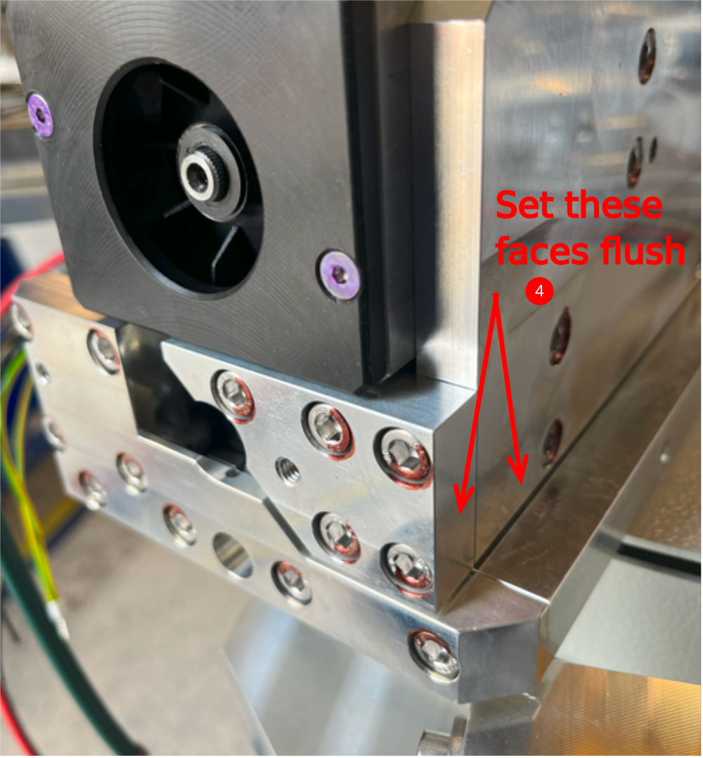
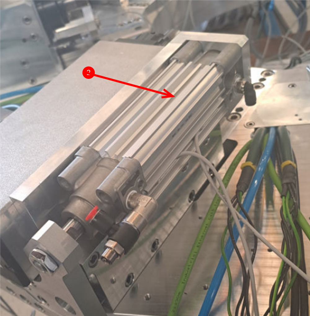
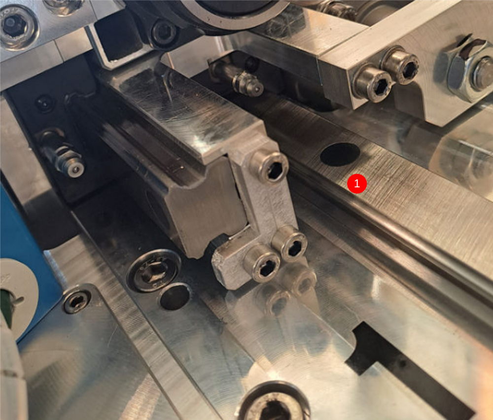
Étape 5 - Fixed P bracket only Mount single plunge spindle cylinder 2,4,6 and 8 Adjustable P bracket
1 Position pre assembled cylinder as shown on spindles 2,4,6 and 8
2 Set P bracket flush on faces indicated and secure with 2 off M5 x 25 socket caps and A form washers . Finalise fasteners
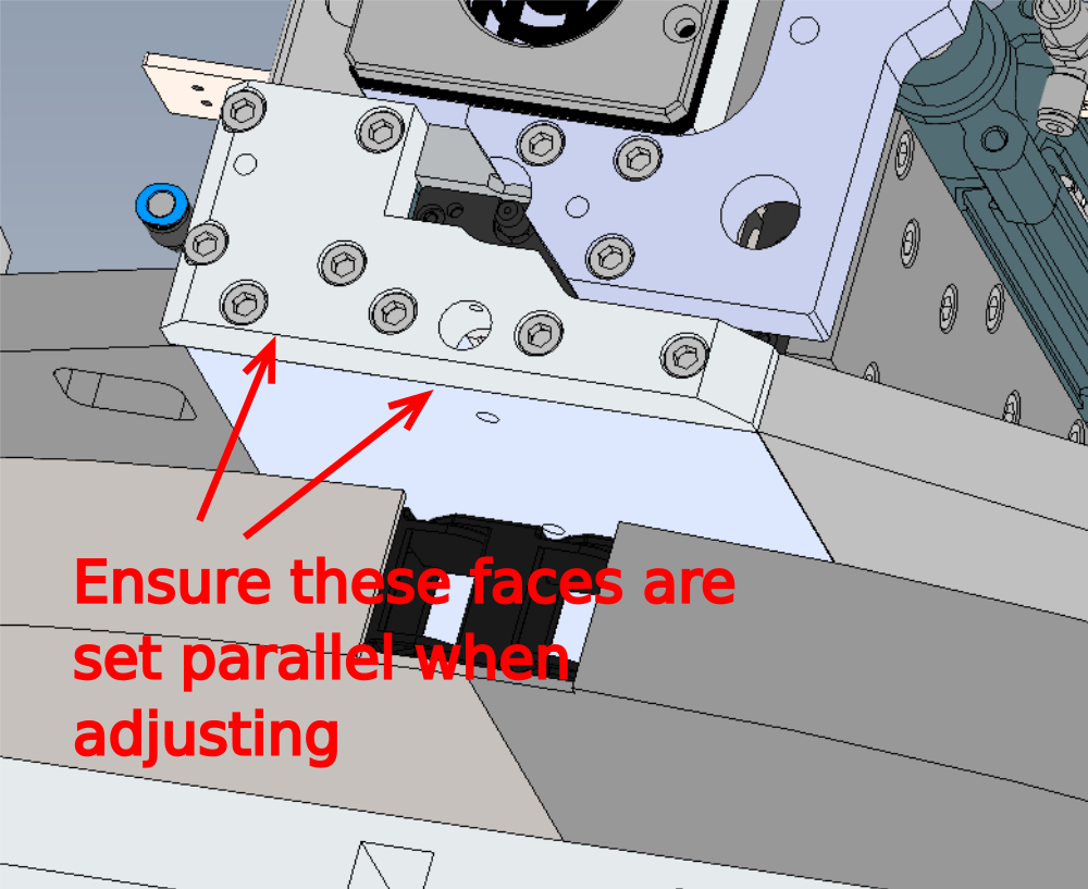
3 Fit D0007790 bracket using 4 off M6x20 socket caps. Set bottom of bracket and bottom of spindle plate flush or parallel . Finalise fasteners
4 Secure base of cylinder as shown using 4 off M6 x 25 socket caps. Finalise fasteners
5 Move assembly by hand to check for smooth running and correct operation


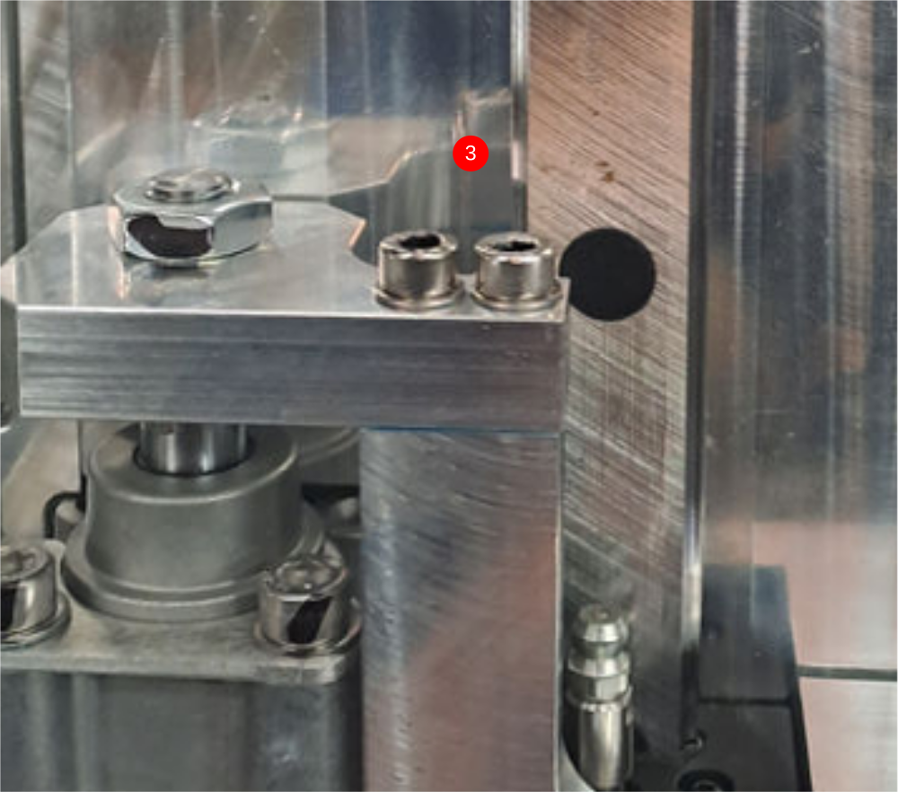
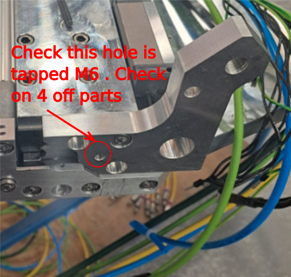
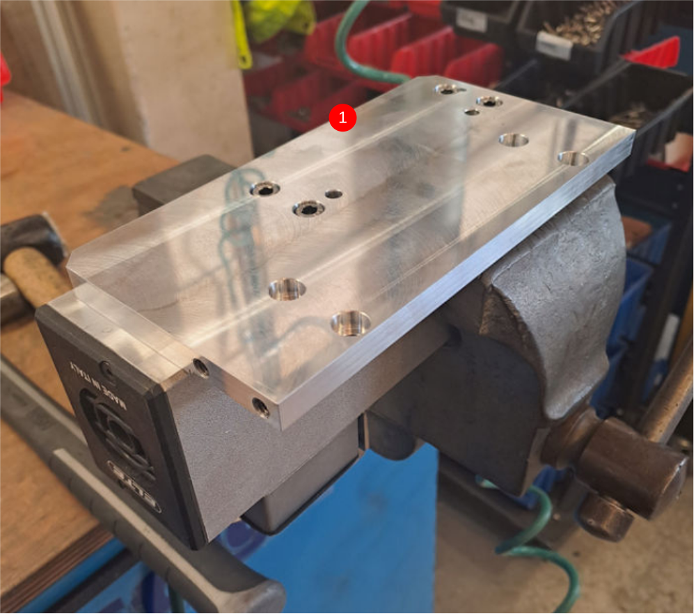
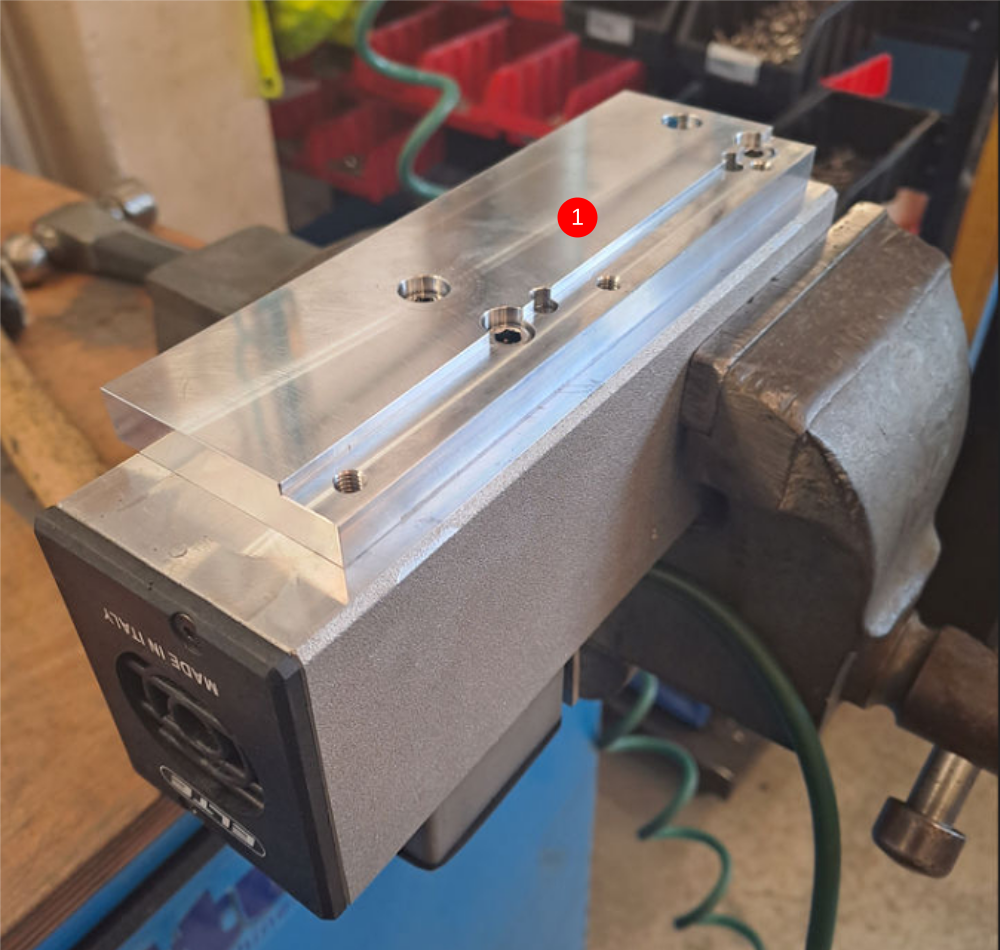
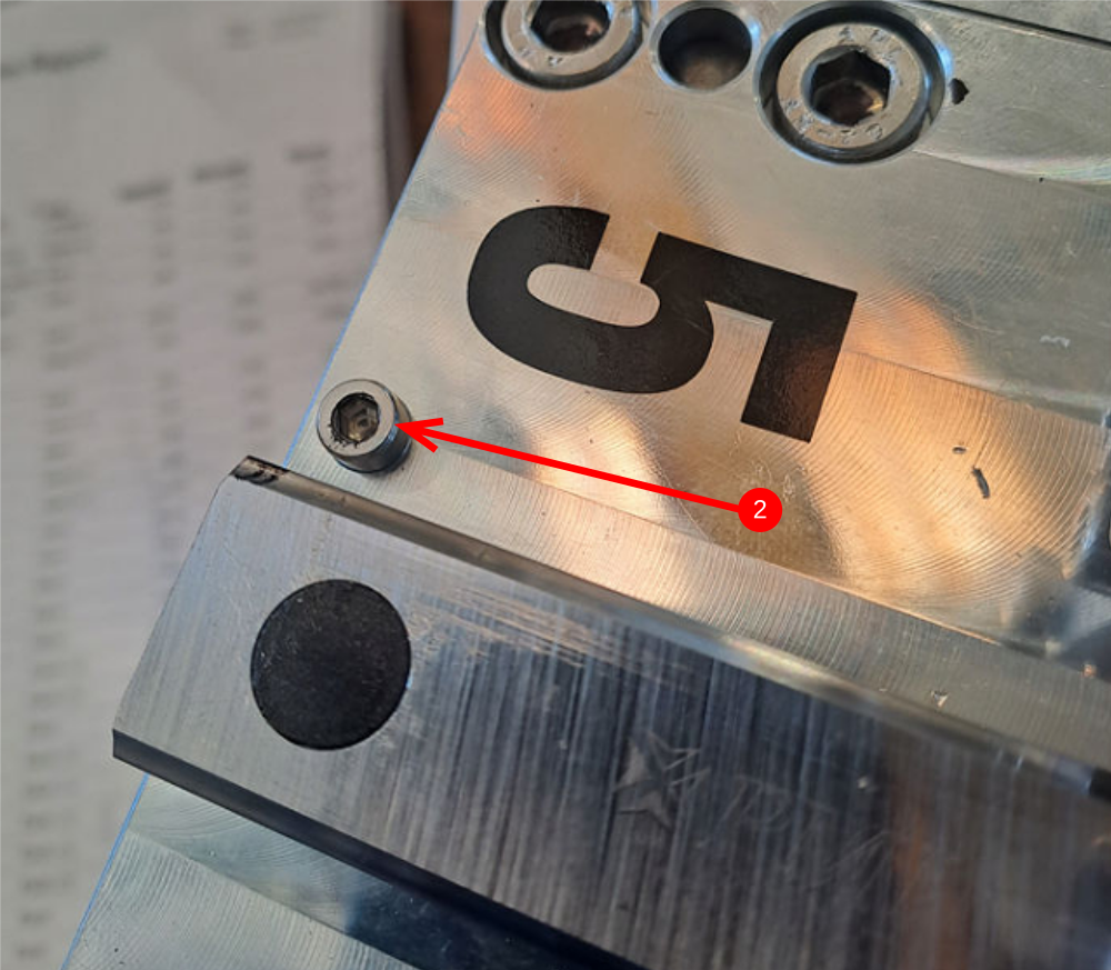
Étape 6 - Check D0007649
Check that component D0007649 has been manufactured correctly
Indicated hole should be tapped M6. Rework and report if not To M6 tapped spec
Étape 7 - Adjustable P Bracket only Mount double plunge spindle cylinder 1,3,5 and 7
Adjustable P Bracket only
Do not add final tension to bolts until alignment has been achieved
1 Attach pre built cylinder anchor to end of cylinder
2 Position pre built cylinder on slide base assembly as shown
3 Use 2 off m5 x 25 socket caps with A form washers to attach to slide base
4 Temporarily mount D0007649 with 1 off m6 x 20 socket cap
5 Attach D0007790 cylinder anchor with 4 off M6 x 20 socket caps
6 Attach Cylinder base to anchor with 4 off M6x 20 socket caps
Étape 8 - Adjustable P Bracket only Align components and set position
Adjustable P Bracket only
1 Use cylinder stroke adjustment to align these two faces
2 Apply Loctite 243 to cylinder nut and tighten
3 Use clearance in holes for mounting at points indicated to achieve cylinder alignment. Cylinder stroke should be even and free along entire stroke
4 Finalise bolts
Repeat on all four single spindles (1,3,5 and 7))
Étape 9 - Fixed P Bracket only Mount double plunge spindle cylinder 1,3,5 and 7
Fixed P Bracket only
1 Position pre assembled cylinder as shown on spindles 2,4,6 and 8
2 Set P bracket flush on faces indicated and secure with 2 off M5 x 25 socket caps and A form washers . Finalise fasteners
3 Fit D0007790 bracket using 4 off M6x20 socket caps. Set bottom of bracket and bottom of spindle plate flush or parallel . Finalise fasteners
4 Secure base of cylinder as shown using 4 off M6 x 25 socket caps. Finalise fasteners
5 Move assembly by hand to check for smooth running and correct operation


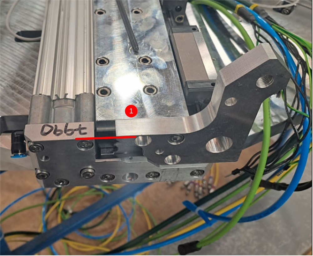
Étape 10 - Adjustable P Bracket only Attach single plunge motor plate
Adjustable P Bracket only
Spindles 2,4,6,8
1 Attach D0007686 motor plate to elte motor using 4 off m6 x 12 socket caps and 2 off 6mmx 20 dowels
2 Attach to single spindle using 4 off m6 x 16 socket caps
Ensure that motor plate butts up to indicated parts and also register is aligned as shown
3 use 5 off m6 x 20 socket caps used to finalise end plate . ensure mounting is even to motor plate
Étape 11 - Fixed P Bracket only Attach single plunge motor plate
4 off
Spindles 2,4,6,8
1 Attach D0007686 motor plate to elte motor using 4 off m6 x 12 socket caps and 2 off 6mmx 20 dowels
2 Fit D0007648 to each spindle using 3 off M6 x 20 socket caps , apply adhesive but only light tension
3 Attach motor to single spindle using 4 off m6 x 16 socket caps
Ensure that motor plate butts up to indicated parts and also register is aligned as shown
4 Finalise D0007648. Glue and fit additional 2 off M6 x 20 socket caps and set faces flush as shown. Finalise fasteners


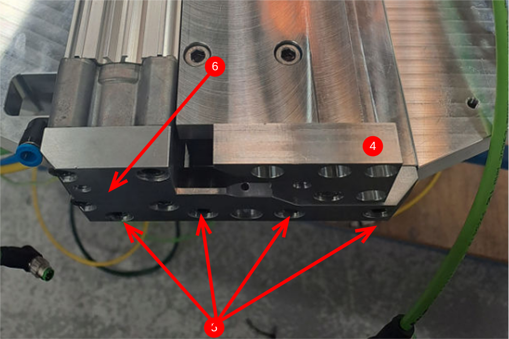
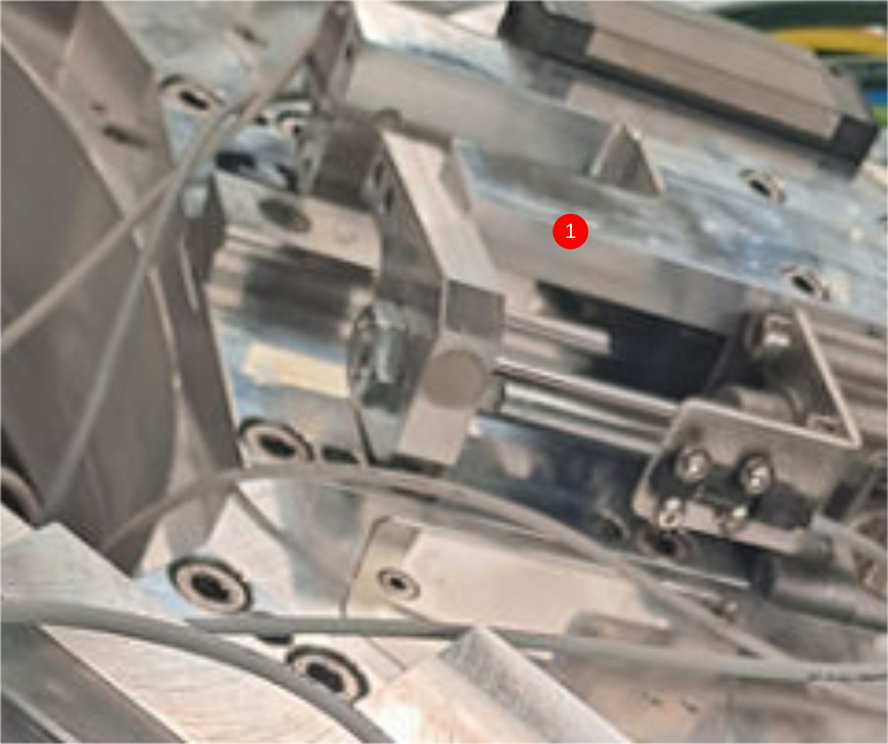
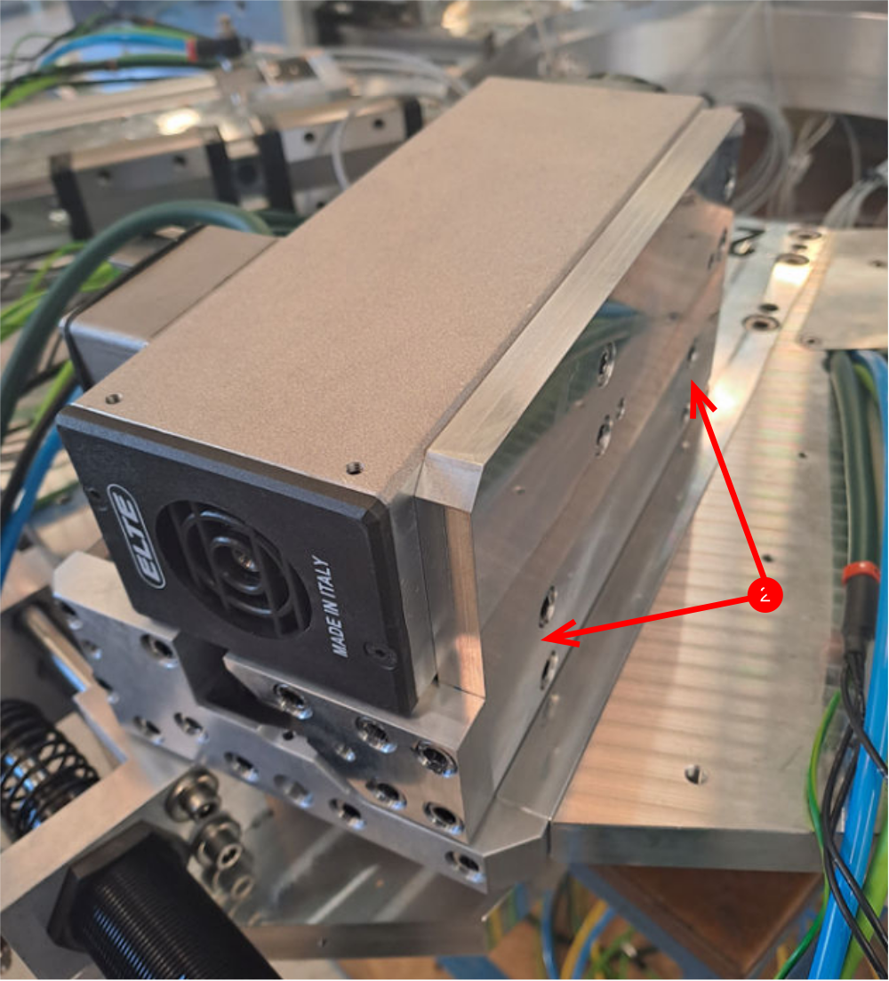
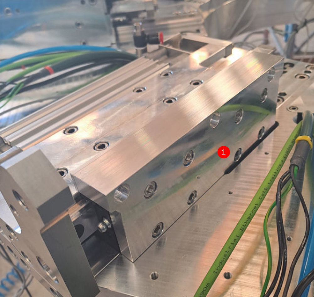
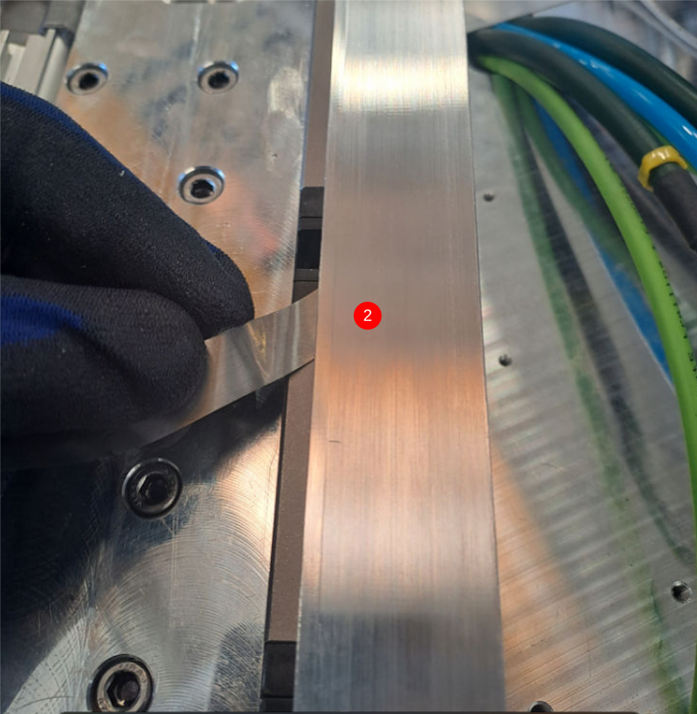
Étape 12 - Double plunge assembly motor mount
4 off
1 Lightly Fix D0007723 motor mount to bearings as shown . Use 8 off M6 x 12 socket caps to fix.
2 Use 0.05mm feeler gauge to check datum faces are in contact, if not remove and inspect parts
3 Finalise bolts
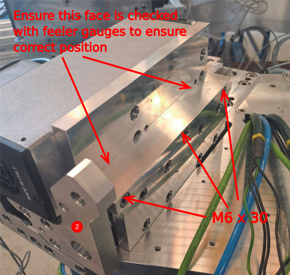
Étape 13 - Mounting double plunge motor
4 off
1 Mount D0007687 motor plate to elte motor with 4 off M6 x 12 socket caps and 2 off 6mm x 20 dowels
2 Use 3 off M6 x 30 socket caps and mount elte motor as shown
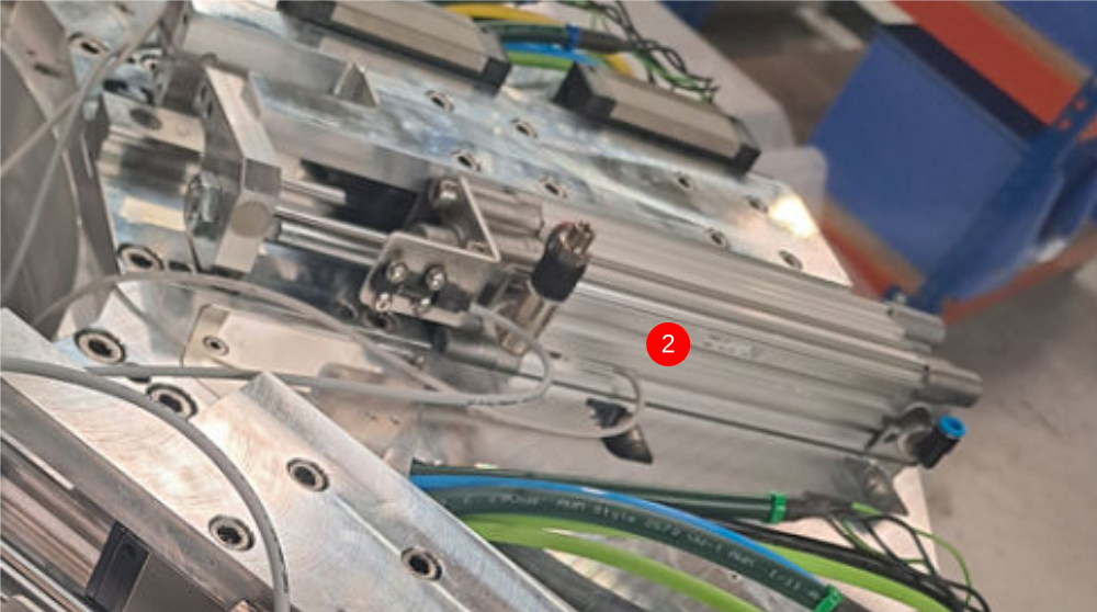
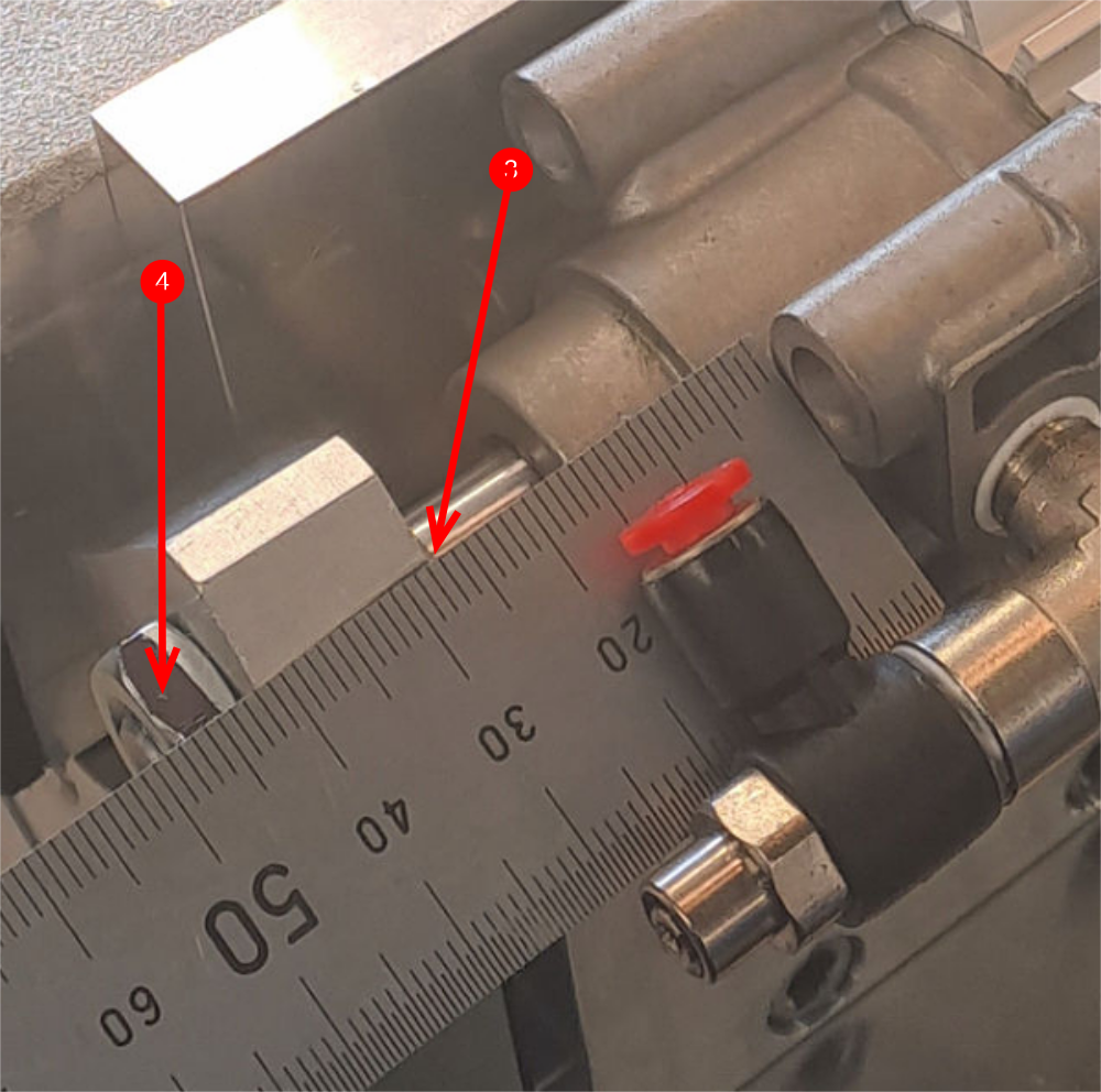
Étape 14 - Mount double plunge cylinder
4 off
1 Attach D0007600 cylinder mount using 2 off M5 x 20 socket caps
2 Attach lighty pre built cylinder assembly using 4 off M6 x 20 socket caps
3 Attach cylinder thread and adjust stroke of cylinder to achieve measurement of 28mm
4 Adhesive and lock off cylinder nut
5 Use clearance in indicated holes to achieve correct cylinder alignment . Stroke of cylinder should be free and consistent
6 Finalise all bolts
Étape 15 - Mount hard stops
1 Use M5 x 16 socket caps to mount 4 off D00015856 hard stops to double plunge assemblies
2 Use 8 off m4x 12 socket caps and fix to all slide bases as a hard stop
Draft
 Français
 English
 Deutsch
 Español
 Italiano
 Português