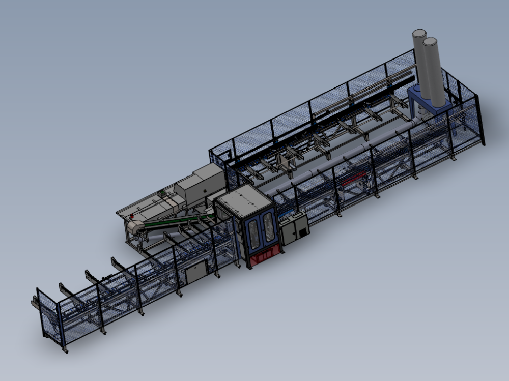
Key Steps for mechanical installation of ZX5

Difficulté
Très difficile
Durée
1 minute(s)
Sommaire
- 1 Introduction
- 2 Étape 1 - Check roller alignment
- 3 Étape 2 - Multi head levelling points
- 4 Étape 3 - Alignment of Machining center to outfeed table
- 5 Étape 4 - Finalise Module C outfeed table alignment
- 6 Étape 5 - Module B adjustment
- 7 Étape 6 - Recheck all settings once final adjustment has been made
- 8 Étape 7 - Position Module A Infeed Table
- 9 Étape 8 - Machining centre Infeed levelling
- 10 Étape 9 - Finalise alignment
- 11 Étape 10 - Module F Saw Alignment points
- 12 Étape 11 - Position Module F
- 13 Étape 12 - Level Module F
- 14 Étape 13 - Quality check
- 15 Étape 14 - Saw Height Adjustment
- 16 Étape 15 - Laser alignment of Saw to Saw infeed height
- 17 Étape 16 - Adjust alignment Saw module
- 18 Étape 17 - Check laser alignment
- 19 Étape 18 - Quality Check
- 20 Étape 19 - Position saw outfeed table
- 21 Étape 20 - Saw Outfeed table leveling
- 22 Étape 21 - Saw outfeed height adjustment and Y axis position
- 23 Étape 22 - Fit Swarf conveyor
- 24 Étape 23 - Install Cable transfer basket
- 25 Étape 24 - Pneumatic /electrical connections
- 26 Étape 25 - Position Extraction unit and pipe work
- 27 Étape 26 - Install front and rear Fence assemblies
- 28 Étape 27 - Machine Guarding
- 29 Commentaires
Introduction
Key data for installation of ZX5
Dokit to generate consistency of installation
Quality checks for installation
Étape 1 - Check roller alignment
Check X axis alignment of horiczontal and vertical rollers using 2 meter straight edge and feeler gauges
Any discrepancy must be reported and rectified if present
Tolerance 0.002" / 0.05mm
[1]R0015311 Install and Align Datum rollers


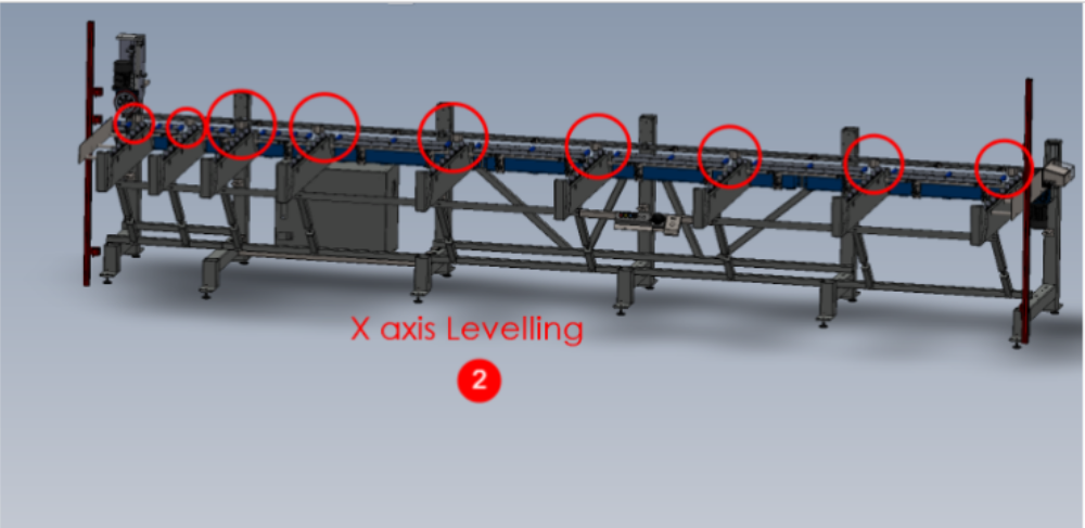
Étape 2 - Multi head levelling points
- x axis machine levelling. use a 2 meter straight edge between the indicated points and an engineers level on top to level this axis
- Y axis levelling. Use an engineers level to straddle the 2 indicated points to level the y axis of the machine
R0015311 Install and Align Datum rollers
R0002913E Install and Align Rotary head Subframe


Étape 3 - Alignment of Machining center to outfeed table
Machining center is aligned to the outfeed using the following
Grip pin setting jig
Laser level
2 meter straight edge
X axis position is determined by hepco rail travel at full extent and center clamp bar within machining center. The gap here should be approximately 75mm.
Y axis position is determined by the grip pin jig and the machining center backfence rollers. The grip pin jig must be used at 2 points for correct alignment . Infeed datum rollers and v notch datum rollers.
Ensure gripper pins fall freely and centrally into alignment jig when setting.
Only move Machining centre to adjust this position
Height is determined by the datum horizontal rollers in the machining center and the blue rollers on the outfeed table. Out feed rollers and platform should be less than 1mm below the Machining centre rollers
- position machining center roughly in place on the end of the outfeed table
- level using previous step
- once the module has been levelled, final levelling of the outfeed x axis can be done , as it uses the machining center as a datum to hold the laser level
Position gripper carriage as close to the laser level as possible
Mark a horizontal line of the carriage plate as a height datum
Move the carriage to above the next section of frame feet and adjust the pair of jacking bolts to adjust line to be on laser level mark
Repeat this step above every pair of frame legs where jacking bolts areThese steps will ensure the outfeed is now set on a dead flat plain
4. Use the pin jig to adjust the position of the machining center to allow the gripper pins to align with the jig at all points along the back fence rollers. hepco beam should also be moved from in to the out position also to double check this jig setting
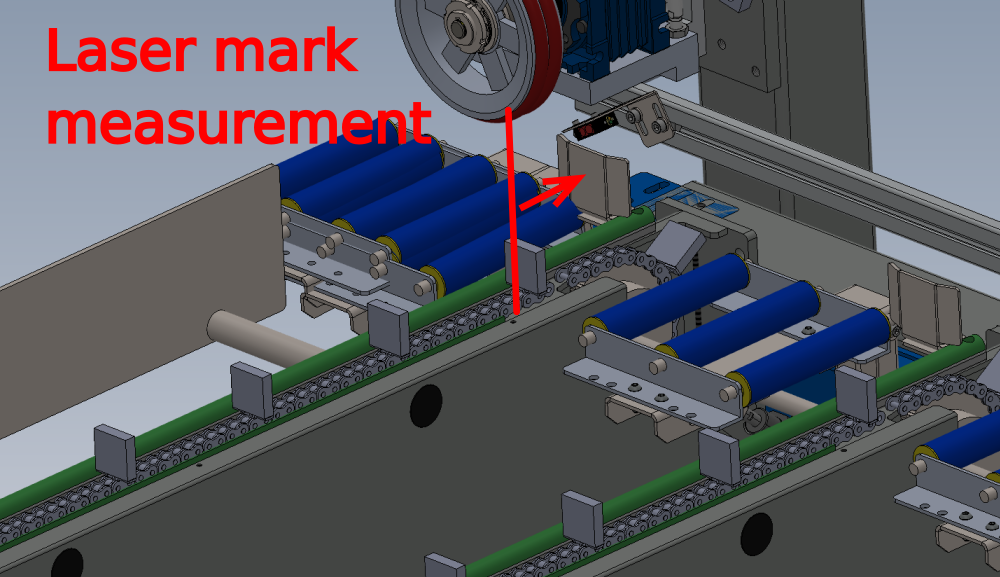
5. Use laser against machining center rollers to cast a laser line along the outfeed. Pull the gripper as close as possible to the laser, and mark a vertical line on the gripper where the laser dot falls.
Move the gripper to the end of the hepco rail and check if the laser stop still aligns on the vertical line previously marked . If it doesn't , grip pin alignment will need re checking as it is crucial that both of these areas are correct
6 final height adjustment is set by using a 2 meter straight edge through the machining center rollers to the first set of rollers on the outfeed table. Machining center can be adjusted up or down to bring these rollers all onto the same height plain (-1mm maximum)

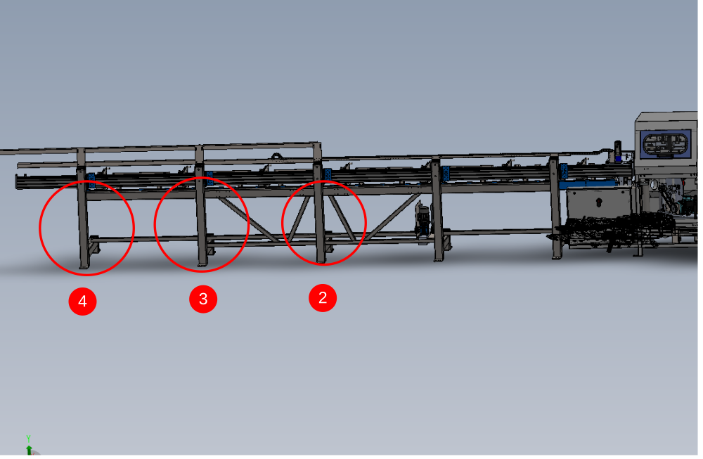
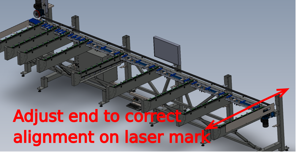
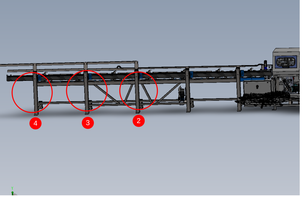
Étape 4 - Finalise Module C outfeed table alignment
1 Place laser base on machining centre rear vertical rollers and cast beam along outfeed frame.
2 Move gripper to be directly in front of laser and mark a vertical line to match laser dot
3 Rotate laser so base is on horizontal rollers and mark horizontal line onto gripper
4 Move gripper to indicated adjusting leg and using the 2 off floor jacking bolts to align laser dot to horizontal mark on gripper.
5 Repeat at adjusting leg 2,3 and 4
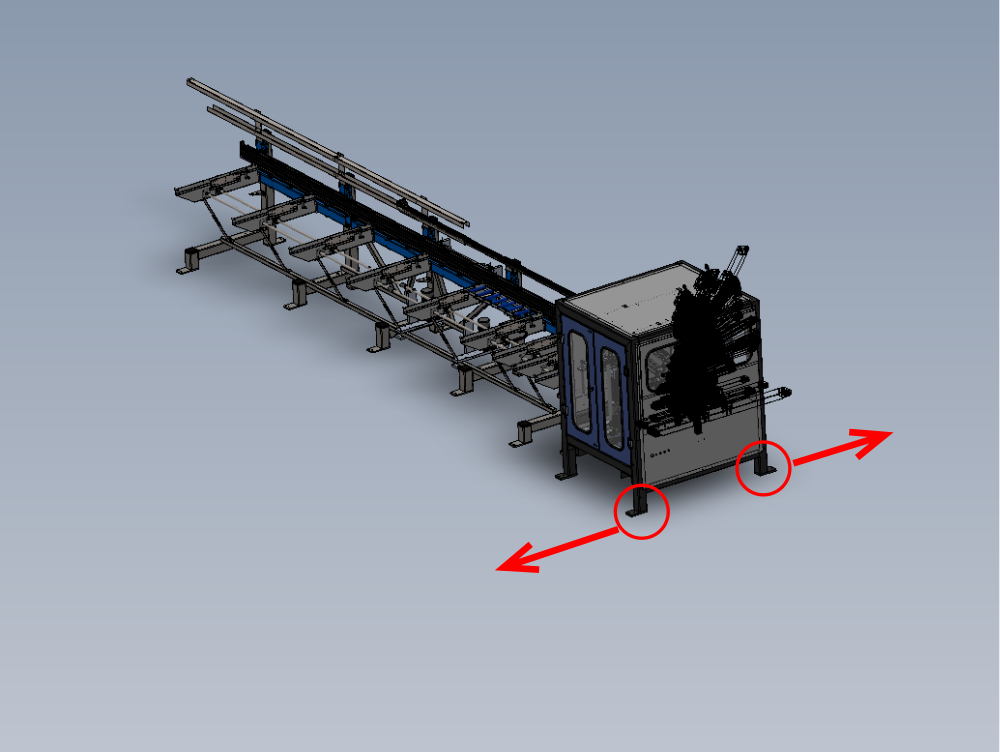
Étape 5 - Module B adjustment
Rotate laser level in module B so base is against back fence rollers
Cast beam onto vertical pen mark on gripper
Adjust machining centre in directions and points shown to correct laser mark if required
Étape 6 - Recheck all settings once final adjustment has been made
Recheck all settings requested , As any adjustments can alter previously set positions
Check machine level
Grip pin positions
Once laser alignment has been set
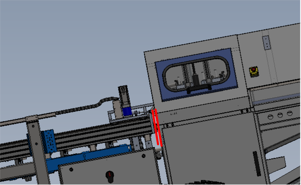
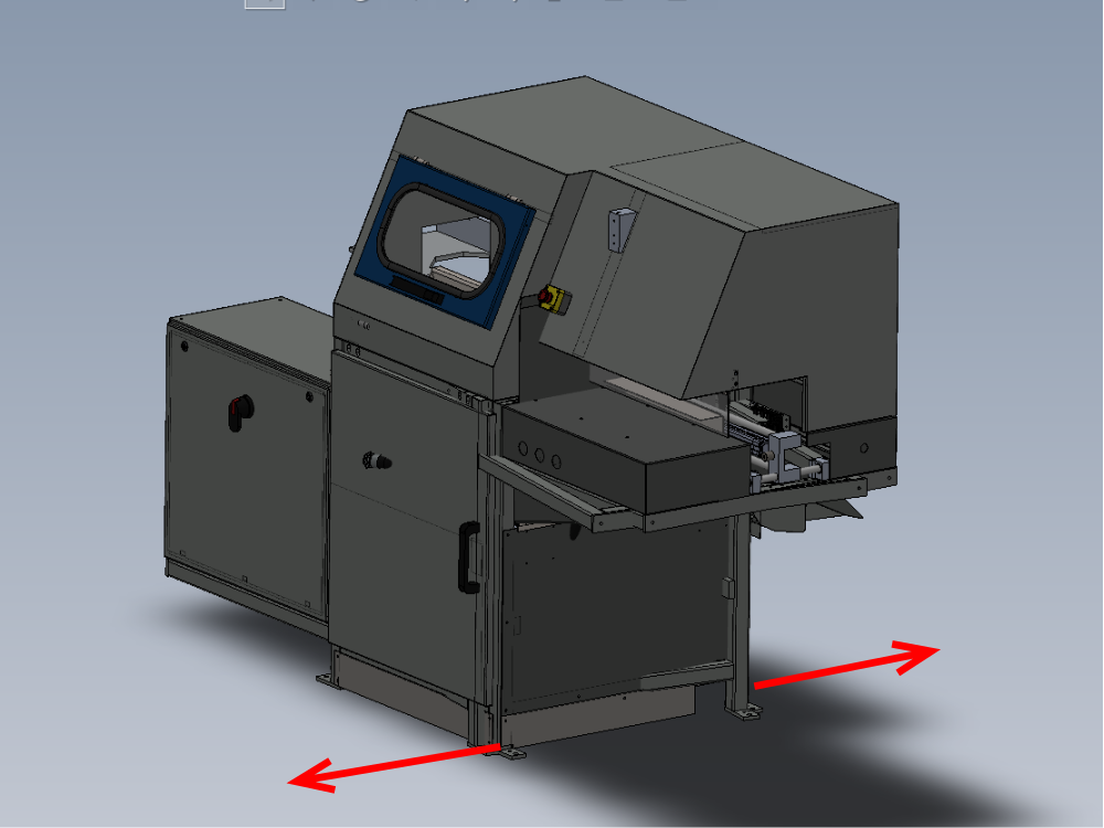
Étape 7 - Position Module A Infeed Table
Position Module A infeed table in front of Module B machining centre
Use Back fence of module A and Module B as y axis alignment point
Position X axis of Module A frame close to B as shown, approximately 23mm from roller assembly to module B clamp assembly
Do not finalise alignment yet, use as rough position markers


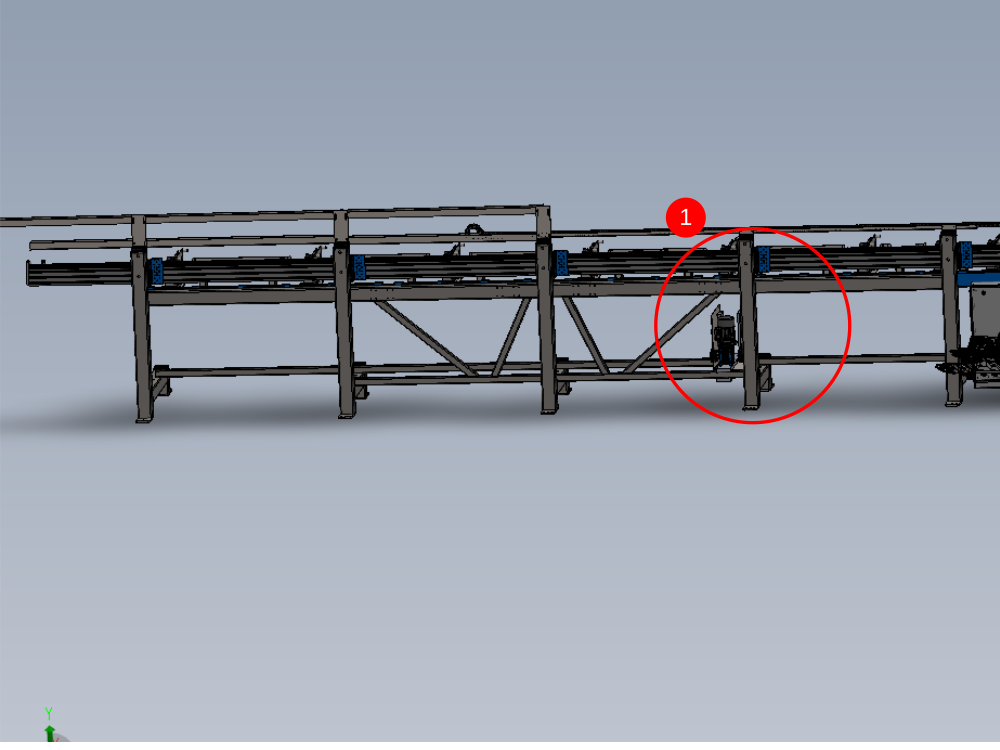
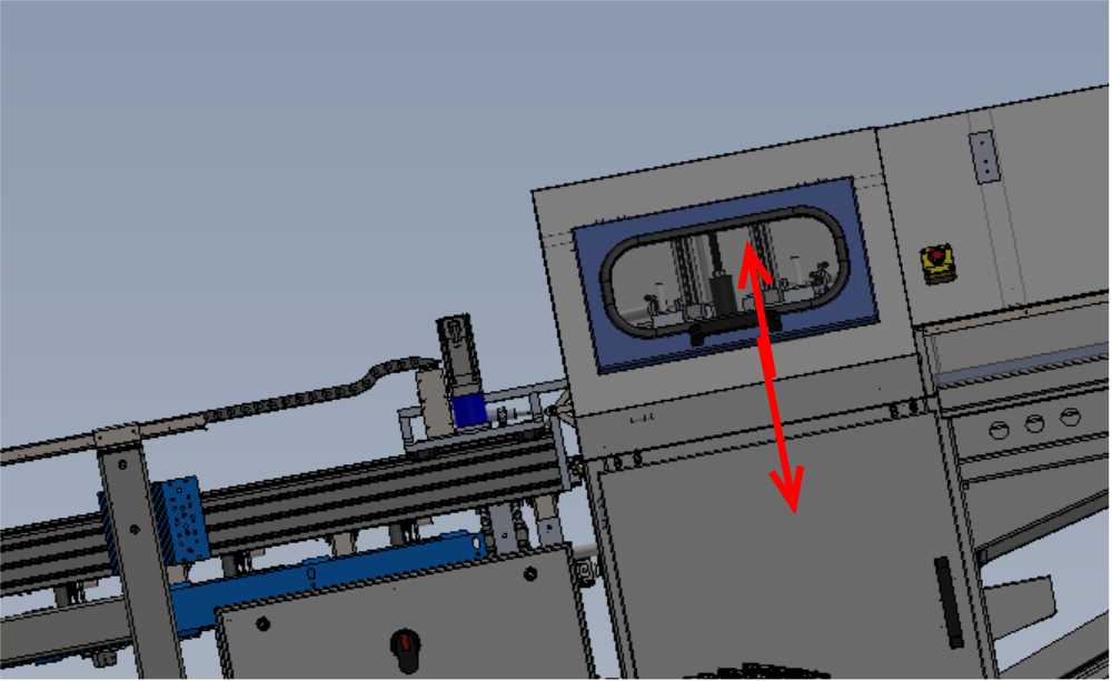
Étape 8 - Machining centre Infeed levelling
Y axis of machining centre infeed . This is done on the indicated face of the arms using a level . Only level the indicated arms as these are the only ones controllable by the jacking feet positions
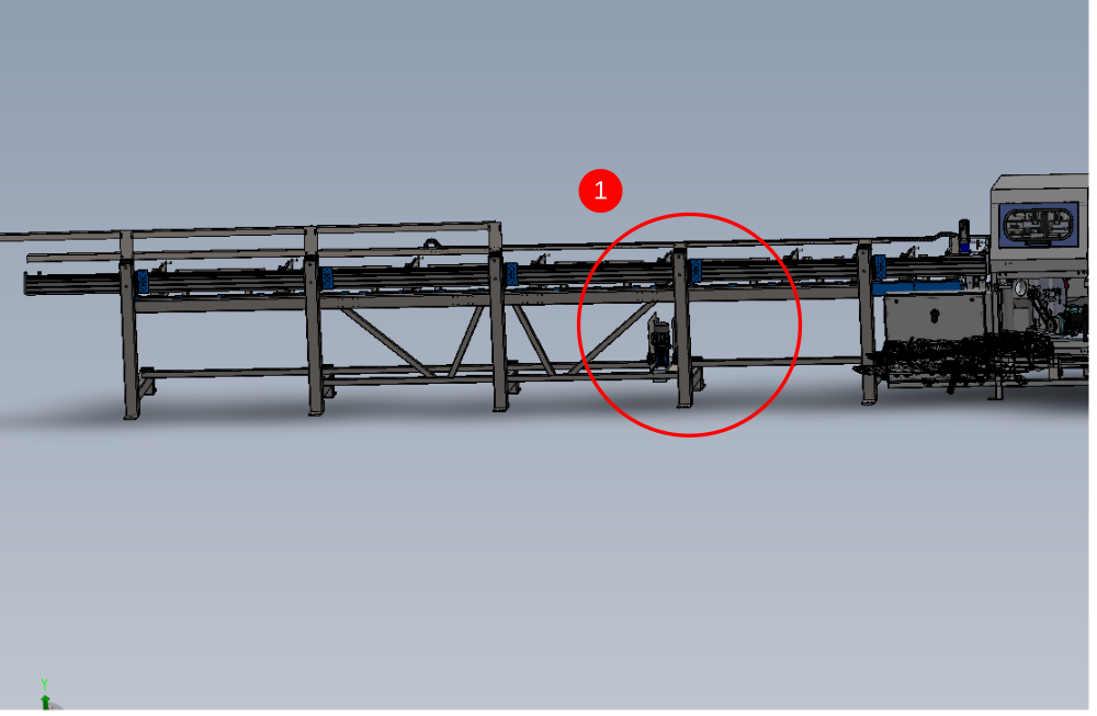
#Use a laser level placed on the levelled machining centre infeed rollers, and cast a laser line along the length of the infeed table. Ensure the beam is positioned so a reading can be taken from each circled point on the frame. Take a measurement from the first circled point with a steel rule of the indicated area. Replicate this measurement at all points indicated along the frame by Adjusting the legs in pairs to raise or lower the appropriate arm
This will ensure the frame is level and flat


Étape 9 - Finalise alignment
Height of module A is determined by load rollers.
Blue load rollers should be -1mm below Module B load rollers . Adjust All jacking points on module A the same amount to lift or lower the frame to match module B.
Y axis alignment is achieved by using laser .
1 Adjust Module A so backfence is behind Module B vertical roller by 1mm maximum
2 Position laser against back fence of module B and cast across Module A frame in front of backfences. Take measurement from first backfence
2 Adjust end of frame to achieve the same laser measurement as taken at first backfence
3 Recheck backfence alignment to module B, and repeat and adjust until all criteria is correct
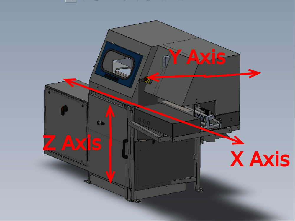
Étape 10 - Module F Saw Alignment points
X axis position is determined by gripper travel
Y axis position is determined back fences
Z axis is determined by cut table to infeed roller height
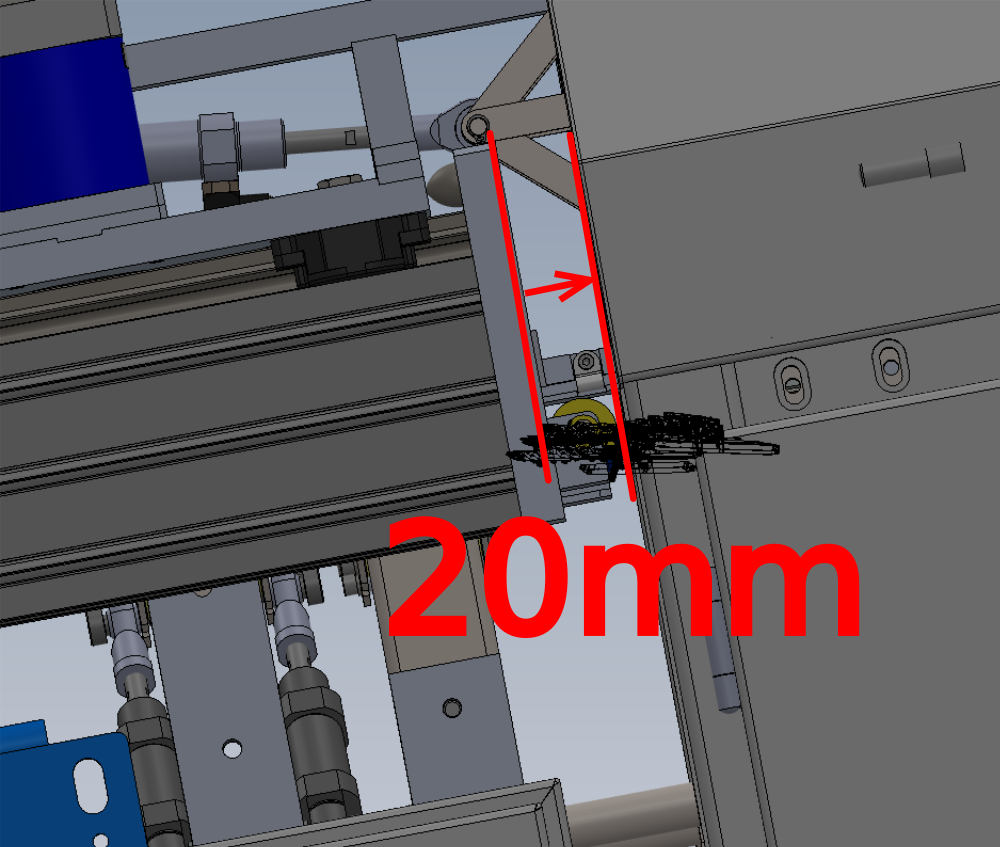
Étape 11 - Position Module F
Position module F at end of Module E infeed frame
Approximately Align Saw roller back fences to Saw infeed back fences
Approximately align X axis position by setting the to frames spaced at the distance shown of 20mm
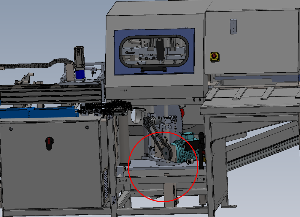
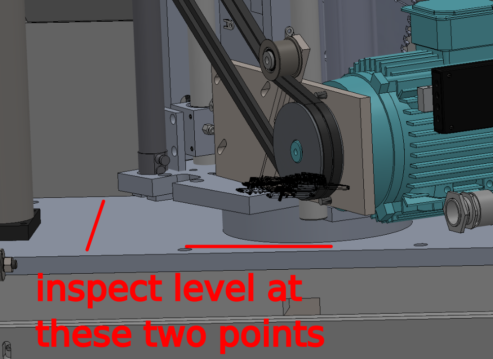
Étape 12 - Level Module F
Use the indicated points to level the frame.
Use cut table indicated as levelling point
Level Y and X Axis of saw


Étape 13 - Quality check
It is vital to confirm Cut tables are in the correct position once levelled, and that movement has occurred during transport
To do this the base of the saw turn table must be checked for level. These readings must read exactly the same as the levelled cut table in the previous step
Any discrepancy should be reported
Étape 14 - Saw Height Adjustment
Saw module should be raised or lowered to align with blue load rollers on saw infeed table
Saw module should sit above blue rollers by no more than 1mm
Ensure levels previously set are not compromised when adjusting height
Double check levels are still correct once height has been adjusted
Étape 15 - Laser alignment of Saw to Saw infeed height
1 Position base of laser against back fence rollers and cast beam towards gripper
2 Position Gripper directly Infront of laser and mark vertical line on gripper to match laser dot
3 Rotate laser so base is on cut table and mark a horizontal line on the gripper to match the laser dot
3 Move Gripper to point one indicated , and inspect horizontal line to laser dot . Any discrepancy can be adjusted by the 2 off adjusting floor bolts directly below
4 Repeat this step and indicated points 2,3 and 4
Étape 16 - Adjust alignment Saw module
Rotate the laser so the base is against the rear roller fence, and ensure the gripper is at its furthest point of travel away from the saw . Project the laser to the gripper. Adjust Saw module in directions shown to align the laser to the vertical mark on gripper
Étape 17 - Check laser alignment
With the laser still casting along the infeed table, slowly return the gripper along the axis and inspect the laser dot in relation to lines added to gripper. Discrepancy should be less than 4mm on both axis
Étape 18 - Quality Check
All settings should be double checked once final adjustments have been made
Machine level
Laser alignment
Grip pin positions
Back fence alignments
Étape 19 - Position saw outfeed table
Approximately position saw out feed table against saw module

Étape 20 - Saw Outfeed table leveling
- X axis of module is levelled from the two indicated points . Use a 2 meter straight edge between these points and an engineers level on top
- y axis is levelled from these two indicated points . an engineers level rested on this face is sufficient for levelling


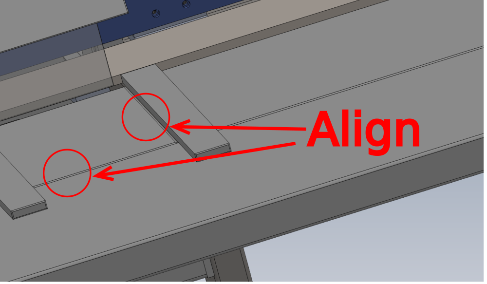
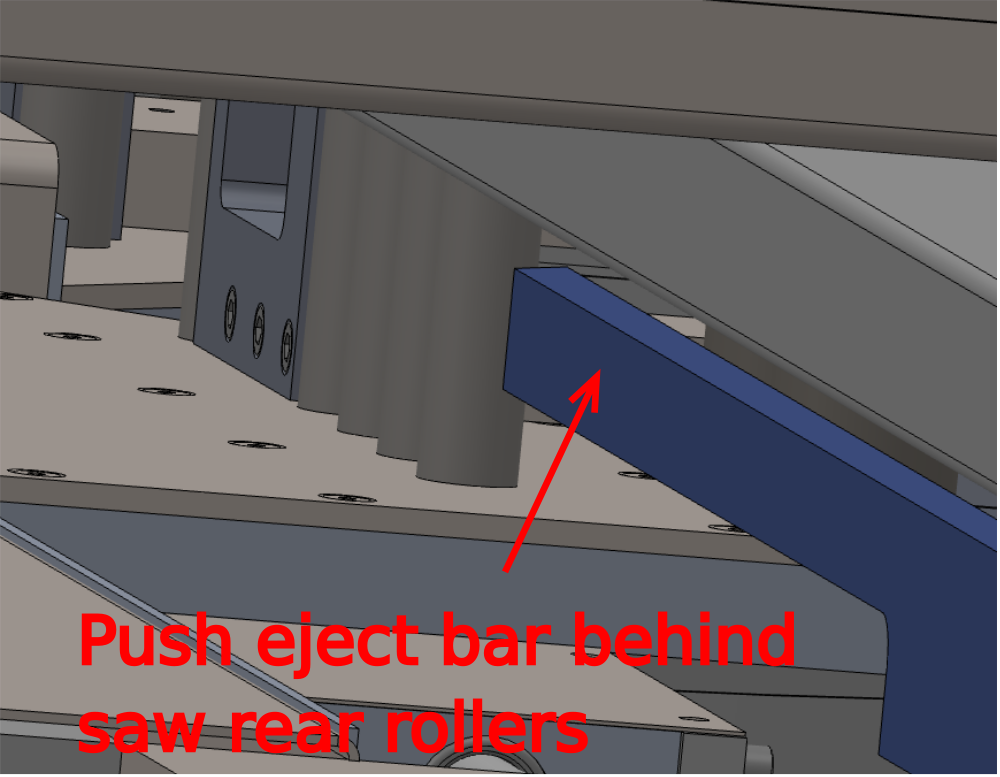
Étape 21 - Saw outfeed height adjustment and Y axis position
Adjust height of saw outfeed table to align faces
Check that eject table cylinder can freely move beneath frame on full range of travel
Check that Blue push bar is behind Saw rear fence rollers
Fix frames together with M10 set bolts and washers
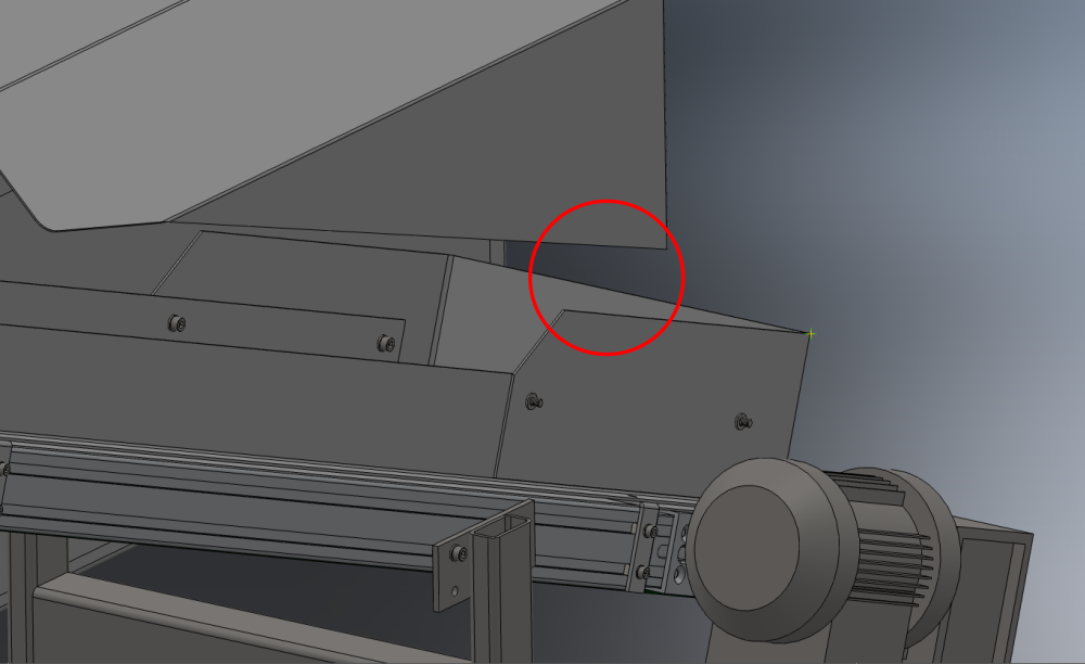
Étape 22 - Fit Swarf conveyor
Fit waste conveyor to out feed frame using 2 off M8 socket caps
Adjust waste conveyor feet to minimise gap shown between saw module rear panel and waste guide on conveyor

Étape 23 - Install Cable transfer basket
Install cable transfer basket as shown


Étape 24 - Pneumatic /electrical connections
Perform electrical / pneumatic connections

Étape 25 - Position Extraction unit and pipe work
Position all extraction components as shown

Étape 26 - Install front and rear Fence assemblies
Install transfer front and rear beam assemblies

Étape 27 - Machine Guarding
Fit remaining guard panels


Draft
 Français
 English
 Deutsch
 Español
 Italiano
 Português