Details for fitting motor and swarf chute


Difficulté
Moyen
Durée
2 heure(s)
Sommaire
- 1 Introduction
- 2 Étape 1 - Unless otherwise stated
- 3 Étape 2 - Mid cut sensor
- 4 Étape 3 - Fit Saw cut sensors
- 5 Étape 4 - Loom sensors
- 6 Étape 5 - Fit motor
- 7 Étape 6 - Quality
- 8 Étape 7 - Fit pulley and belts
- 9 Étape 8 - Fit Infill panel to chute
- 10 Étape 9 - Fit Infill panel to chute
- 11 Étape 10 - Fit chute support
- 12 Étape 11 - Fit chute
- 13 Étape 12 - Quality
- 14 Étape 13 - Align swarf chute and finalise
- 15 Étape 14 - Check spindle clearance and eject clearance
- 16 Étape 15 - Attach anaconda assembly
- 17 Étape 16 - Attach chute flap
- 18 Commentaires
Introduction
Tools Required
standard hex keys
Standard spanner set
1 meter steel rule
Copper slip
Chute flap template jig
Standard Hss drills
Standard taps
Ratchet 3/8 drive and 13mm socket
Copper/hide hammer
Parts Required
B0000048 Taperlock Set SPZ 80-2 1210-24 x 1
B0001175 Saw V-belt (special size 987mm) for 500mm blade x 2
D0005628 Saw chute infill panel x 1
H0004637 Offcut Chute (H0005333) x 1
H0004660 Chute Bracket x 1
P0000609 Reed Switch Mount (Tie Bar) x 3Étape 1 - Unless otherwise stated
All bolts to have Loctite 243 adhesive applied unless otherwise stated
All Threaded Pneumatic connections to have Loctite 570 applied
All bolts to be pen marked once adhesive applied and correct tension added

Étape 2 - Mid cut sensor
Please observe setting of mid cut sensor in next step.
Please ensure position of 122mm pitch is set between sensors as shown in picture on following step


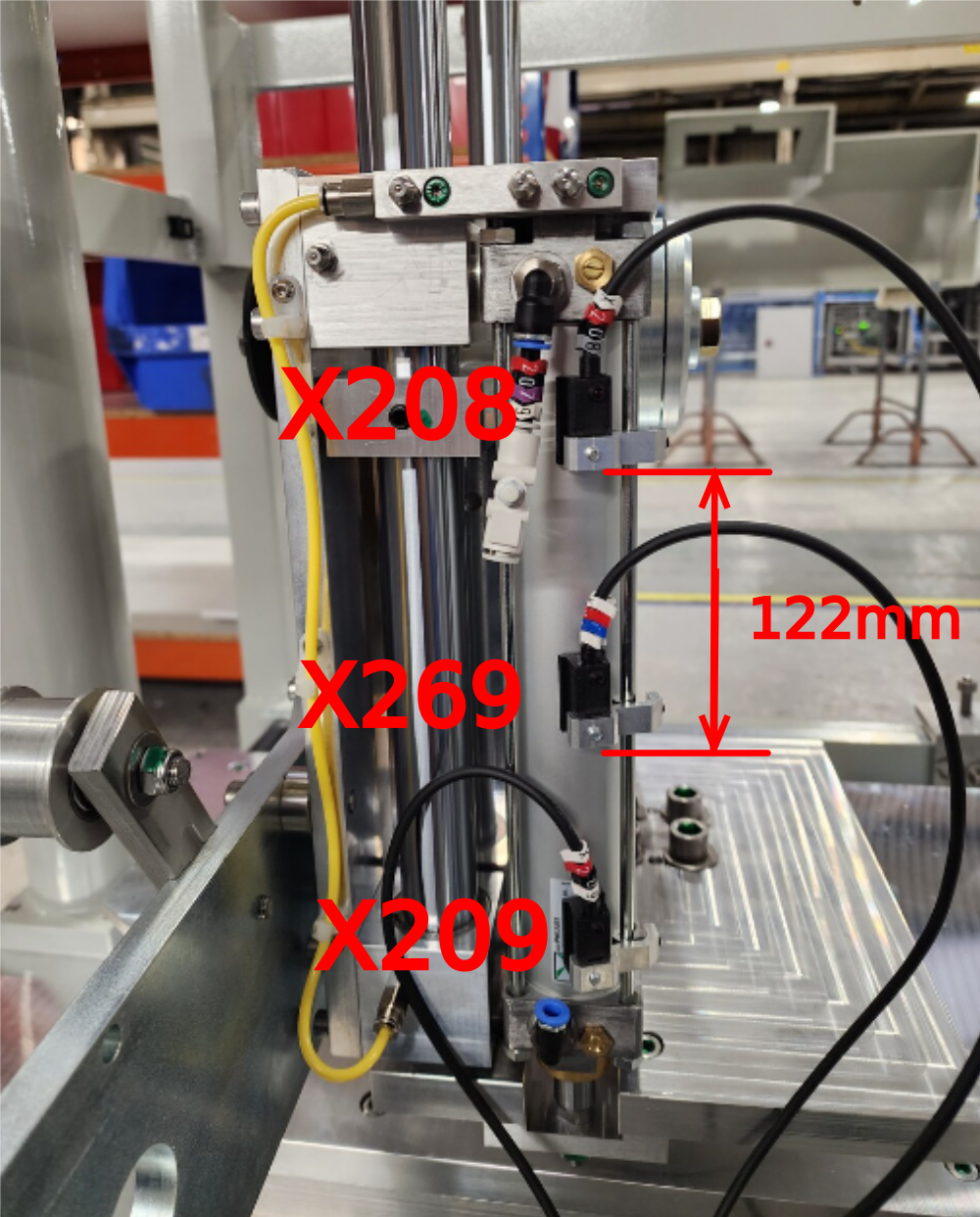
Étape 3 - Fit Saw cut sensors
Fit 3 off saw cut sensors from electrical dept.
Ensure orientated as shown
Labelled as
X208
X209
X269
Use test box to set
X208 at home position. Cylinder contracted
X209 Saw cut out position. Cylinder extended, use air to lift head
X269 Saw mid switch . Set this in the middle of the 2 previous fitted sensors


Étape 4 - Loom sensors
Before fitting motor, ensure cables are loomed onto cylinder rod furthest from blade on inside face, ensuring no cables will be obstructed by stationary block on shaft next to cylinder when head assembly is lifted


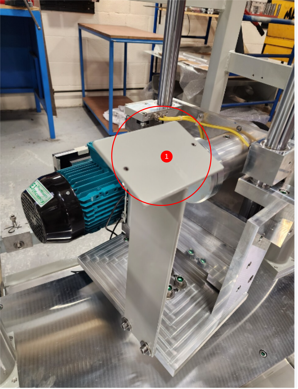
Étape 5 - Fit motor
Fit pre assembled motor to head assembly. Use 2 off M8 Nyloc nuts and A form washers.
Ensure correct orientation


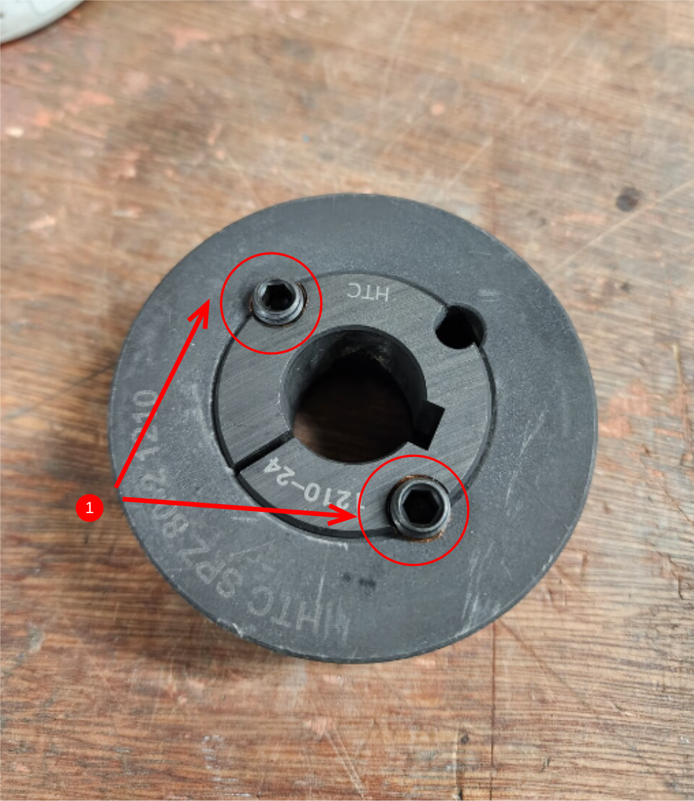
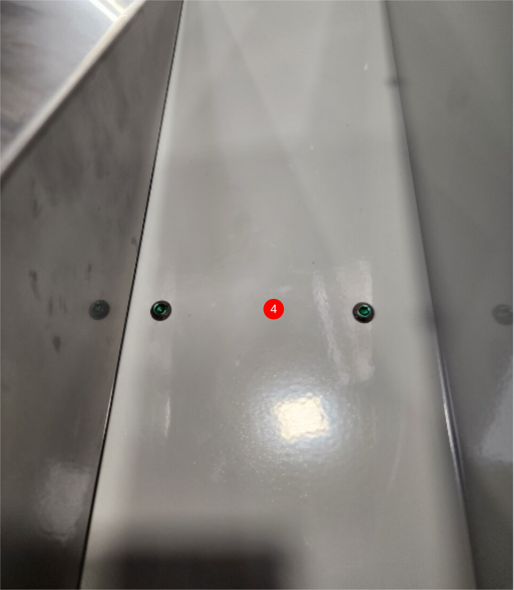
Étape 6 - Quality
Quality instance has been recorded of incorrect setting of taperlock pulleys
Please ensure the following information is adhered too
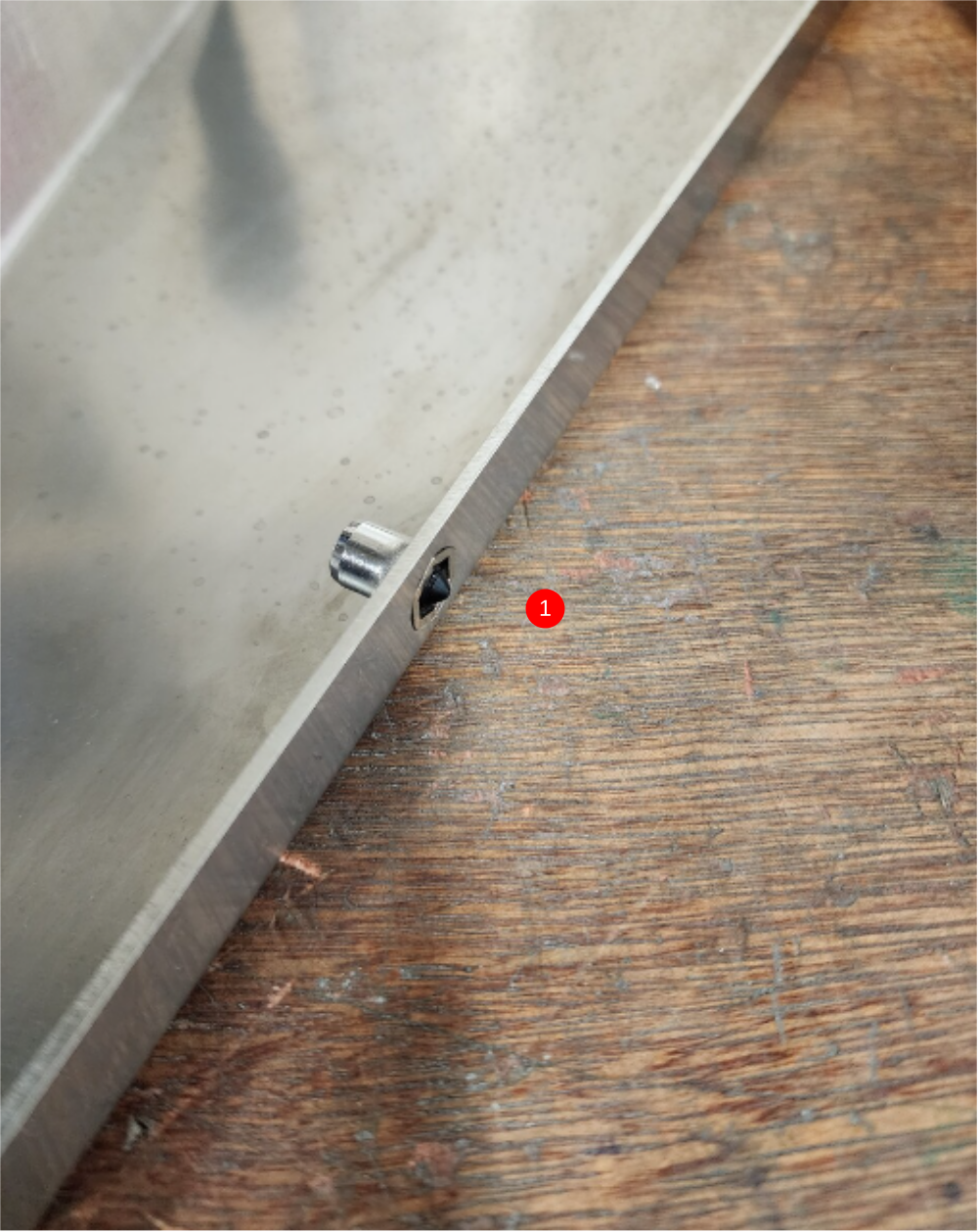
1 Each taperlock should have 2 grubscrews fitted in the positions shown
2 Grubscrews should have copper slip applied and tightened to acceptable tension (FT)

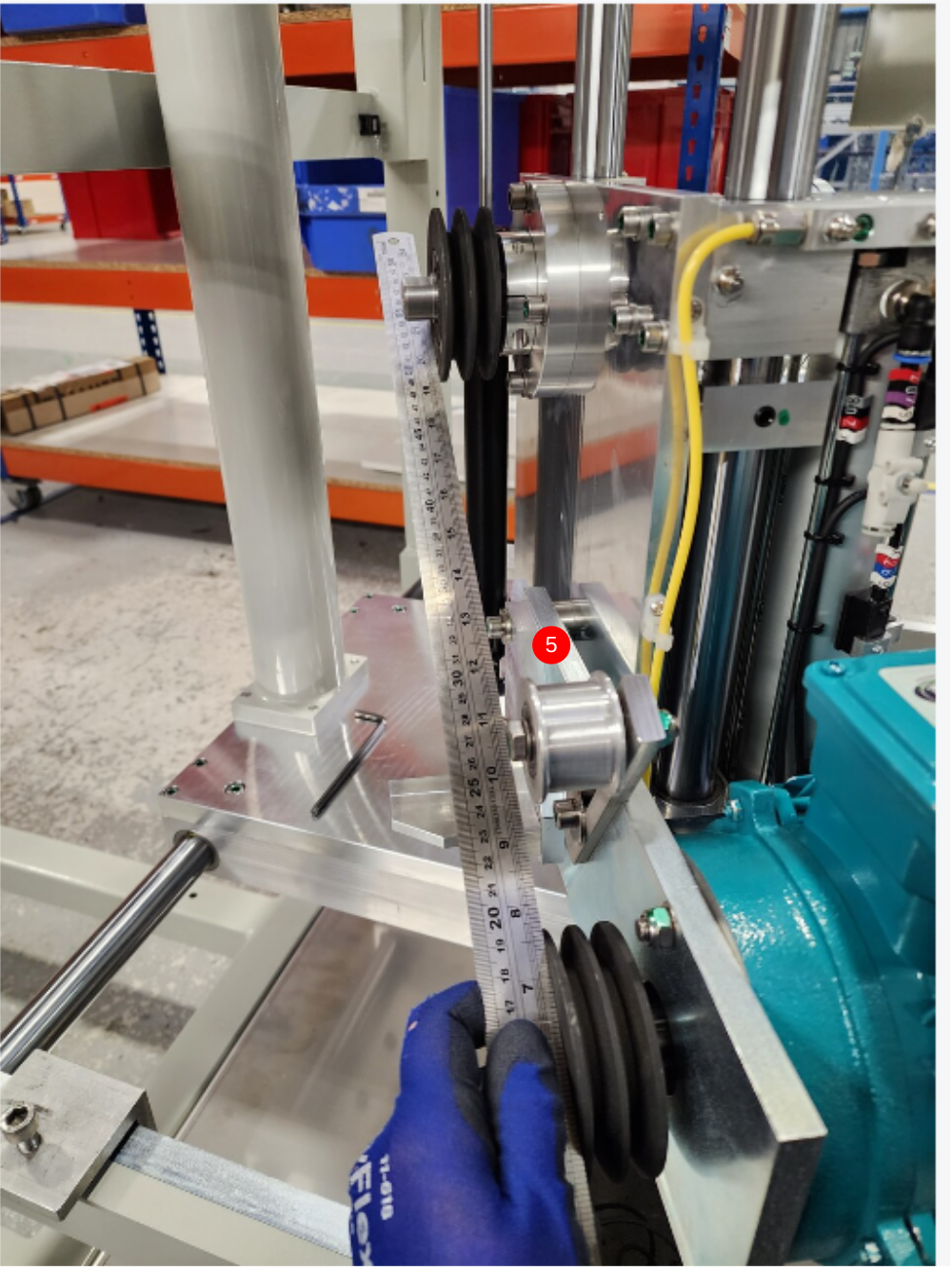
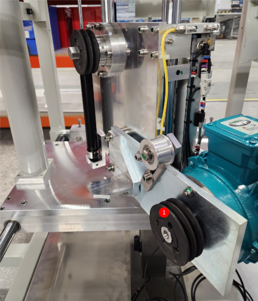
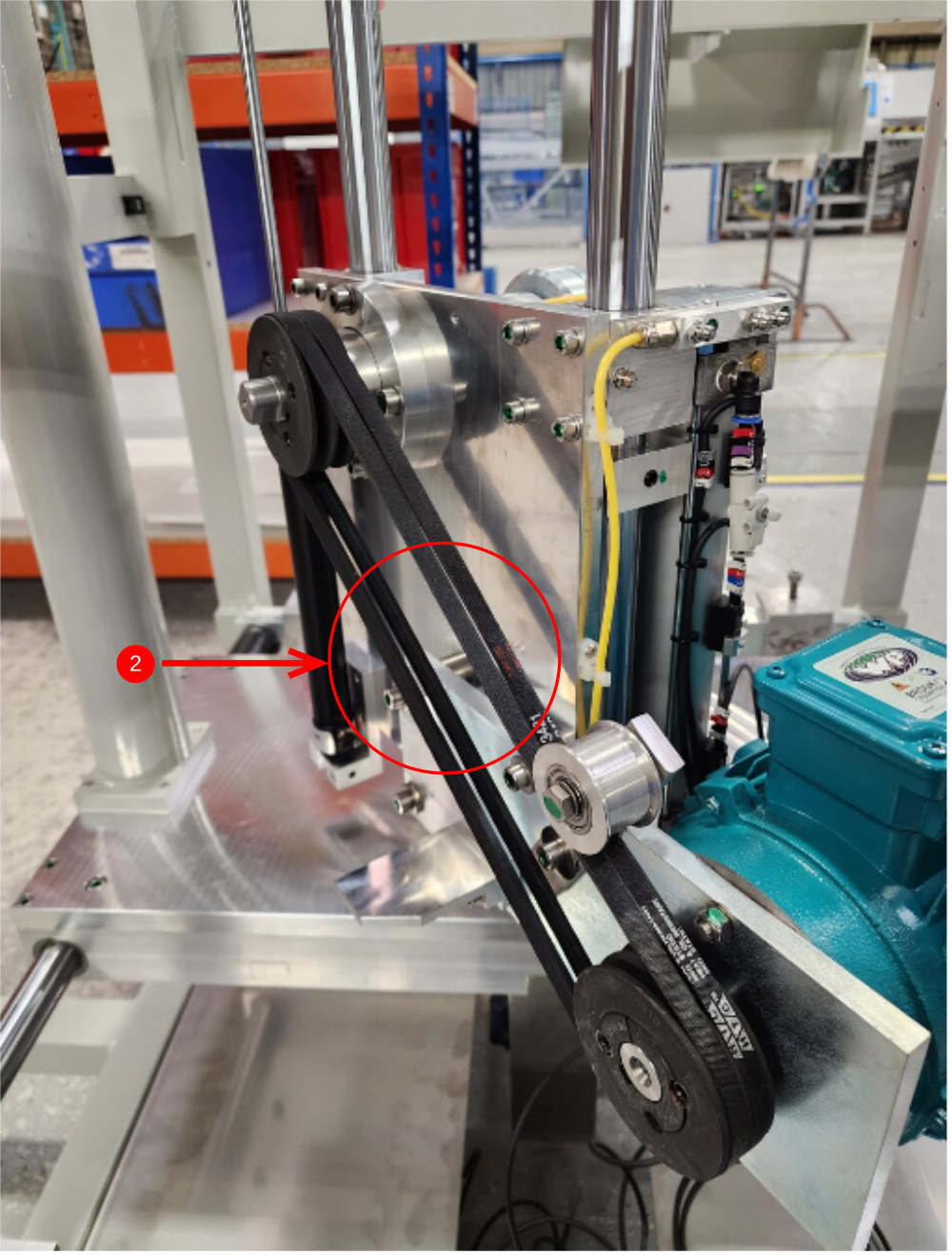
Étape 7 - Fit pulley and belts
1 Fit pulley to saw motor ensure copper slip is used on taper lock grubscrews
2 Fit 2 off belts
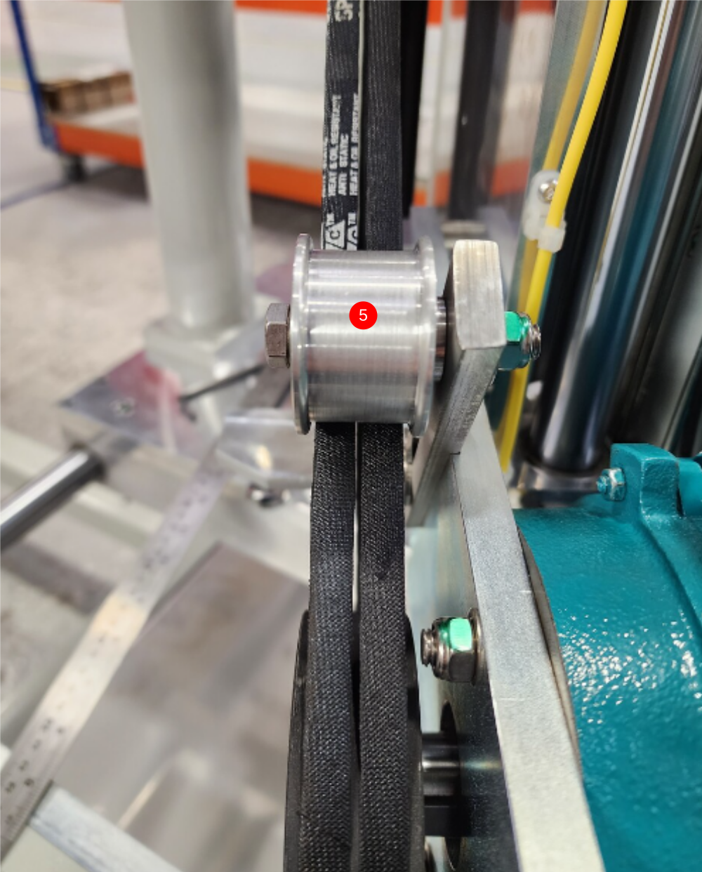
4 Apply tension to belts with belt tensioner
5 Align both pulleys with steel rule, whilst aligning belts to be central on idler puller.
6 Tension all securing grubscrews on both pullers . Pulley will move when tensioned, so take this into account when aligning

Étape 8 - Fit Infill panel to chute
Fit D0005628 Saw chute infill panel to H0004637 Offcut Chute
Use M6 x 10 pointed grubscrews in infill section to use as markers
Position as shown
Use M6 x 12 socket caps with M6 A form washers to fix


Étape 9 - Fit Infill panel to chute


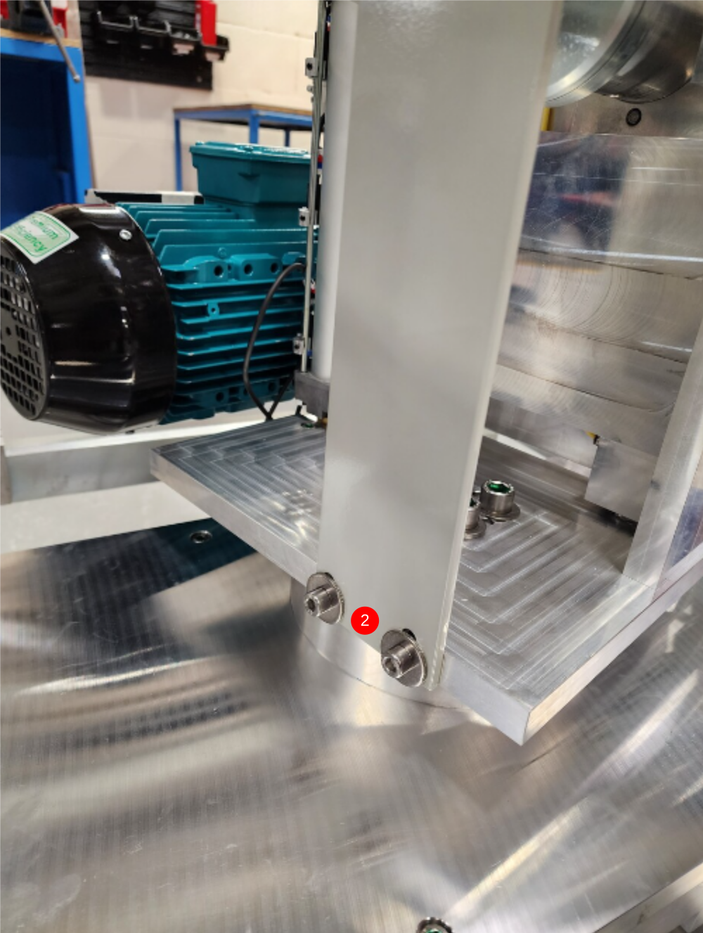
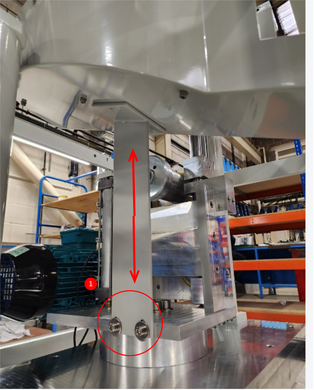
Étape 10 - Fit chute support
1 Tap 2 off M6 tapped holes on top face of bracket
2 Fit chute support to head assembly using 2 off M8 =x25 socket caps and 2 off M8 motor plate washers , do not apply final tension

Étape 11 - Fit chute
Fit swarf chute with 4 off M5 x 10 button socket heads


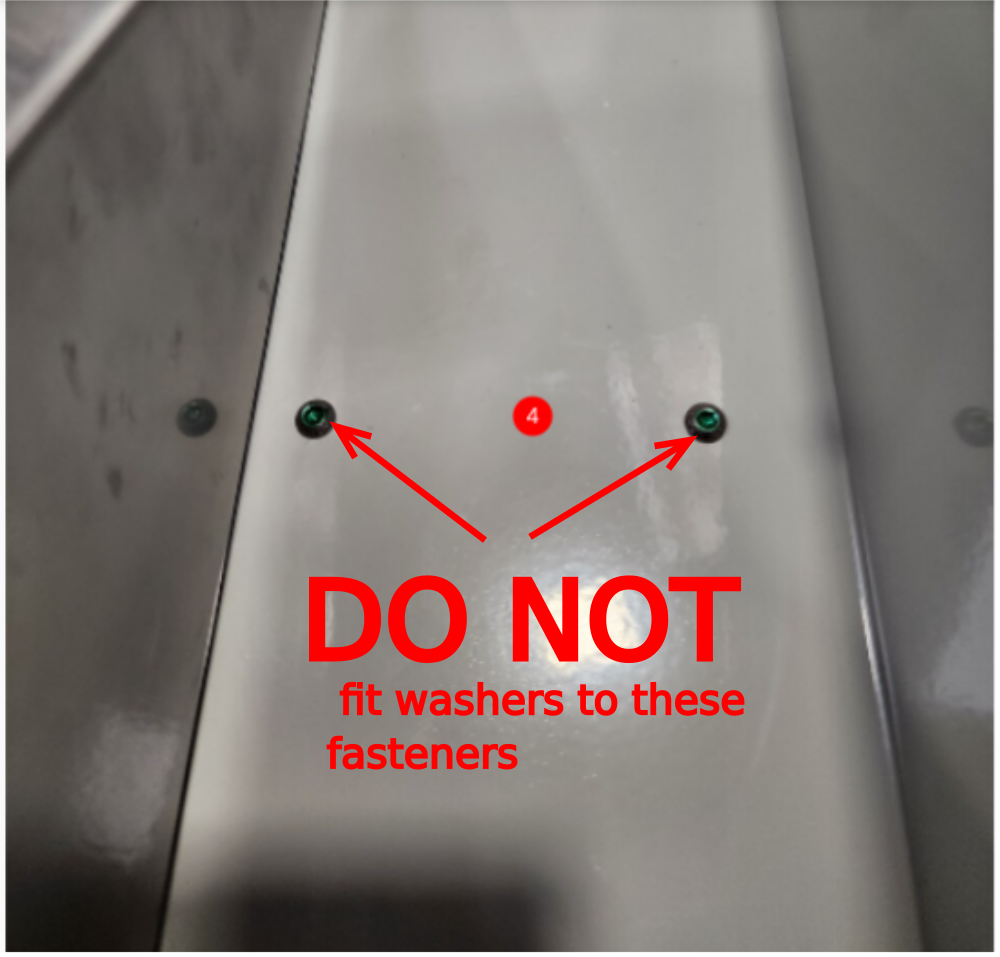
Étape 12 - Quality
When the next step is done, it is vital that only M6 button heads are used to secure swarf chute to support bracket.
Use of washers creates a snag point for profile, so must not be used
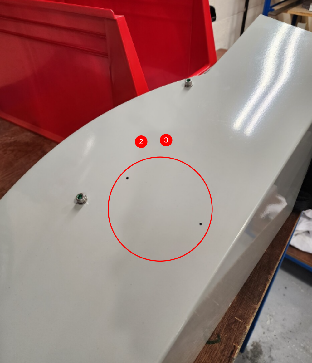
Étape 13 - Align swarf chute and finalise
1 Adjust chute support so chute sits parallel to blade, Use slots on Bracket with M8 fasteners to adjust
2 Mark through 2 off M6 tapped holes on chute support bracket onto swarf chute
3 Remove swarf chute , drill 6.5mm diameter clearance holes
4 Refit swarf chute and secure with M6 x 10 button sockets

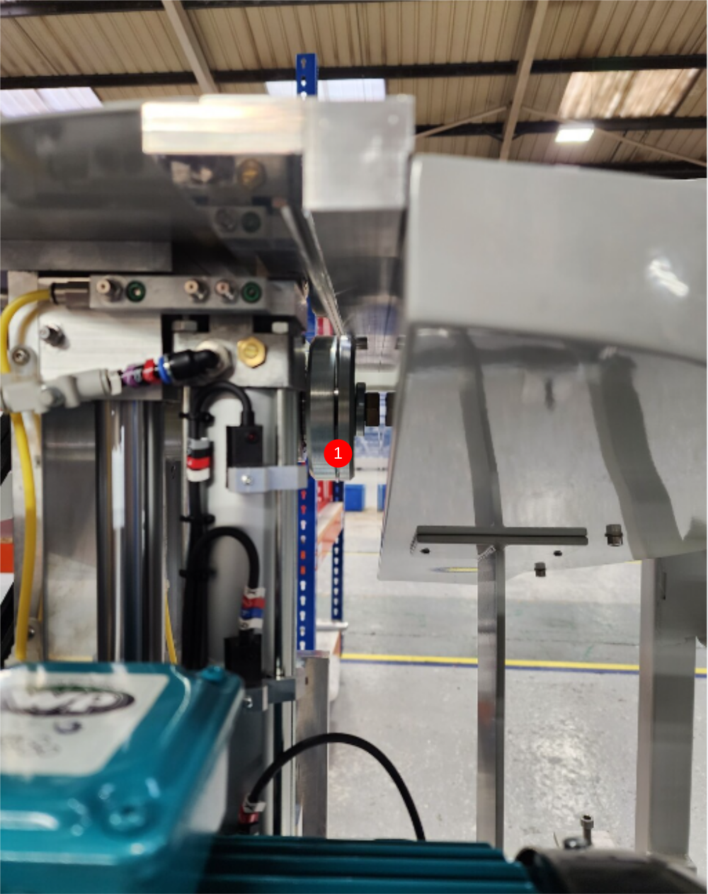
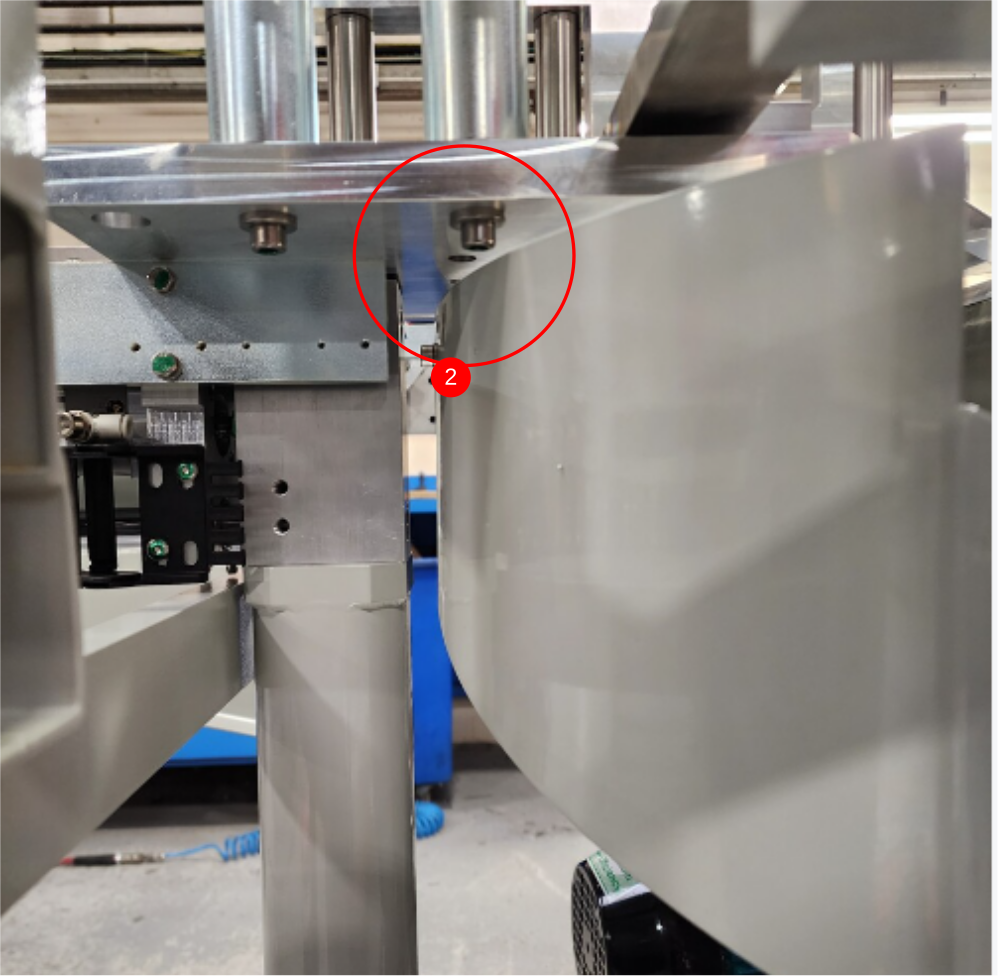
Étape 14 - Check spindle clearance and eject clearance
1 Check spindle clearance once chute is fixed.
Hex head on spindle should clear swarf chute on all points of travel
2 Check that when eject table moves in and out towards saw blade, clearance is present between M8 cap heads and top of chute

Étape 15 - Attach anaconda assembly
Attach saw motor anaconda to frame, using 2 off M6 x 16 socket caps and M6 A Form washers
Ensure dokit Correct Adjustment of Saw Anaconda Rotation is used, to correctly set anaconda


Étape 16 - Attach chute flap
Attach pre built chute flap using M5 x 20 socket caps and M5 A Form washers


Draft
 Français
 English
 Deutsch
 Español
 Italiano
 Português