Connection details for interconnecting pneumatic circuits between ZX5 modules

Difficulté
Difficile
Durée
1 minute(s)
Sommaire
- 1 Introduction
- 2 Étape 1 - Pneumatic pipe identofictions
- 3 Étape 2 - Module A to B
- 4 Étape 3 - Module B Rear pneumatic connections
- 5 Étape 4 - Module D Pneumatic connections
- 6 Étape 5 - Module F connections
- 7 Étape 6 - Module G Saw outfeed connections
- 8 Étape 7 - Waste conveyor blower connection
- 9 Étape 8 - Quality check
- 10 Commentaires
Introduction
Connection details for pneumatics on installation
Étape 1 - Pneumatic pipe identofictions
All control pneumatic connections will be identified with identification numbers
All permanently fed supply lines will be identified by the use of Red pneumatic pipe
All Emergency stop switched air feeds will be identified by the use of Blue pneumatic pipe


Étape 2 - Module A to B
Machining centre to Machining centre Infeed connections
12mm diameter blue pneumatic pipe from Infeed table to connect to Machining centre main Air service unit . Runs along cable basket on infeed table and drops out of end to connect to air service unit
Mains air connection to machine via PCL connector . Do not connect until all subsequent pneumatic connections are complete


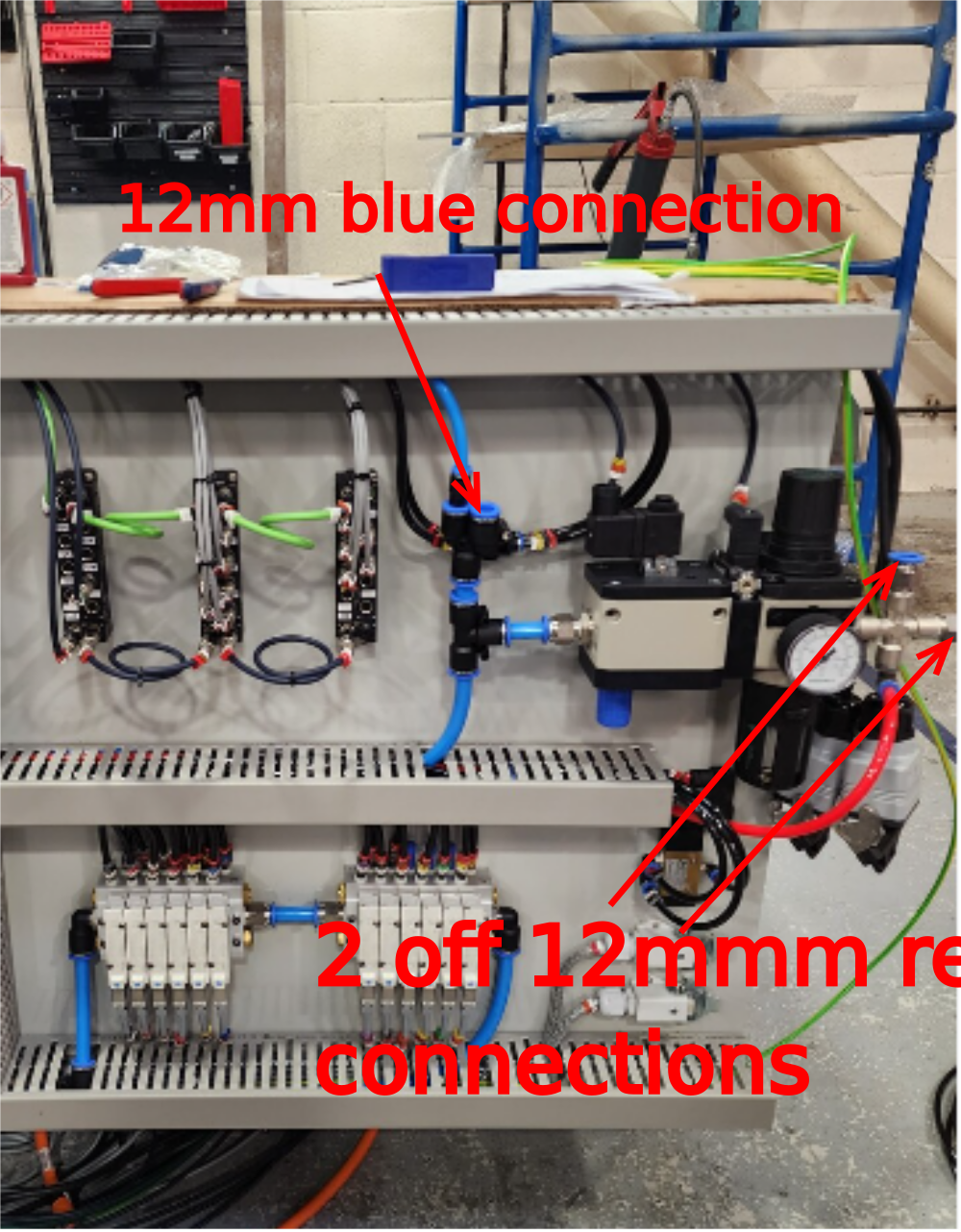
Étape 3 - Module B Rear pneumatic connections
Connections from rear of Module B
- 2 off 12mm diameter Red pneumatic pipes trailing from transfer table wire basket to connect to 12mm bulkhead connections on rear of machining centre. These will be identified as 12mm Red on machining centre
- 1 off 12mm diameter blue pneumatic pipe trailing from module C wire basket to be connected to bulkhead fitting on machining centre. This connection is next to the 2 off red connections and will be identified as 12mm Blue

Étape 4 - Module D Pneumatic connections
Transfer cylinder rails will be identified as follows
2299
2309
2319
2329
2339
2349
Connect each loom from cylinder rail to Tee connections directly beneath


Étape 5 - Module F connections
- 2 off 12mm red pneumatic pipes from transfer table to connect to saw service unit
- 1 off 12mm diameter blue trailing from saw infeed module E to connect to saw service unit

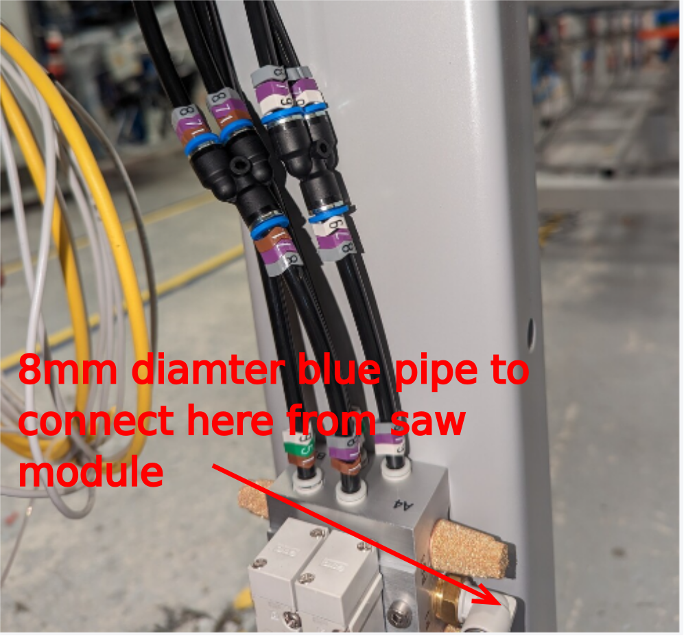
Étape 6 - Module G Saw outfeed connections
8mm Blue diameter trailing from Saw module requires connecting to valve bank attached to outfeed frame
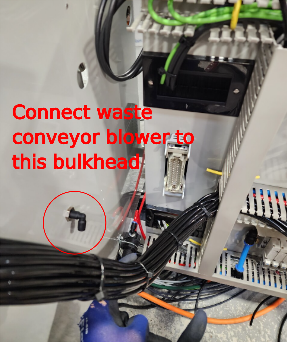
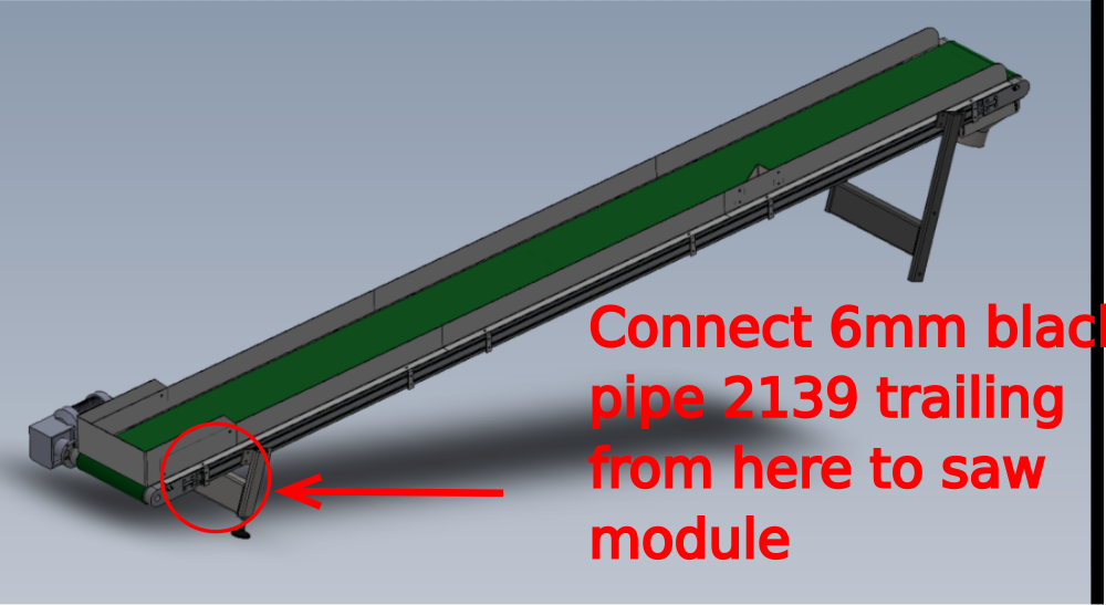
Étape 7 - Waste conveyor blower connection
Connect waste conveyor 6mm black pipe identified as 2139 to be connected to saw module bulkhead connection
Étape 8 - Quality check
Once all pneumatic circuits are connected, all areas should be inspected for audible air leaks, and rectified as discovered

Draft
 Français
 English
 Deutsch
 Español
 Italiano
 Português