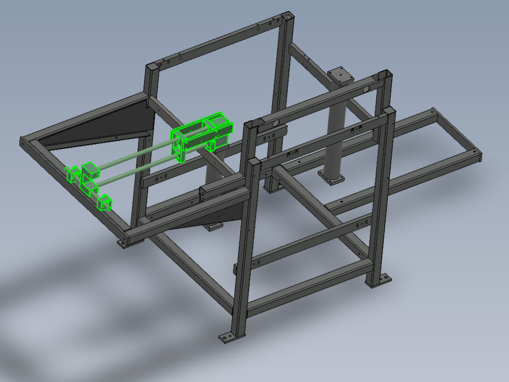
Alignment details for base and 1st stage ejector

Difficulté
Difficile
Durée
4 heure(s)
Sommaire
- 1 Introduction
- 2 Étape 1 - Unless otherwise stated
- 3 Étape 2 - M6 rivnuts
- 4 Étape 3 - Attach eject support
- 5 Étape 4 - Attach Rod base
- 6 Étape 5 - Fit eject bearing blocks
- 7 Étape 6 - position eject shafts
- 8 Étape 7 - Level base
- 9 Étape 8 - Check end plate level
- 10 Étape 9 - Level eject shafts
- 11 Étape 10 - Finalise Grubscrews
- 12 Étape 11 - Fit ejector tie bars
- 13 Étape 12 - Finalise position of base Point 1
- 14 Étape 13 - Finalise position of base Point 2
- 15 Étape 14 - Finalise position of base Point 2
- 16 Étape 15 - Finalise position of base Point 2
- 17 Étape 16 - Check all settings
- 18 Commentaires
Introduction
Tools Required
Standard hex key set
300mm engineers level
Copper /hide hammer
Parts Required
D0004014 Ejector Tie Bar x 2
D0004328 Rod Base (5303) x 1
H0004629 Shaft 20mm: 754 Ejector x 2
R0000570B Bench Assemble 1st stage Ejector and Level Base x 1Étape 1 - Unless otherwise stated
All bolts to have Loctite 243 adhesive applied unless otherwise stated
All Threaded Pneumatic connections to have Loctite 570 applied
All bolts to be pen marked once adhesive applied and correct tension added

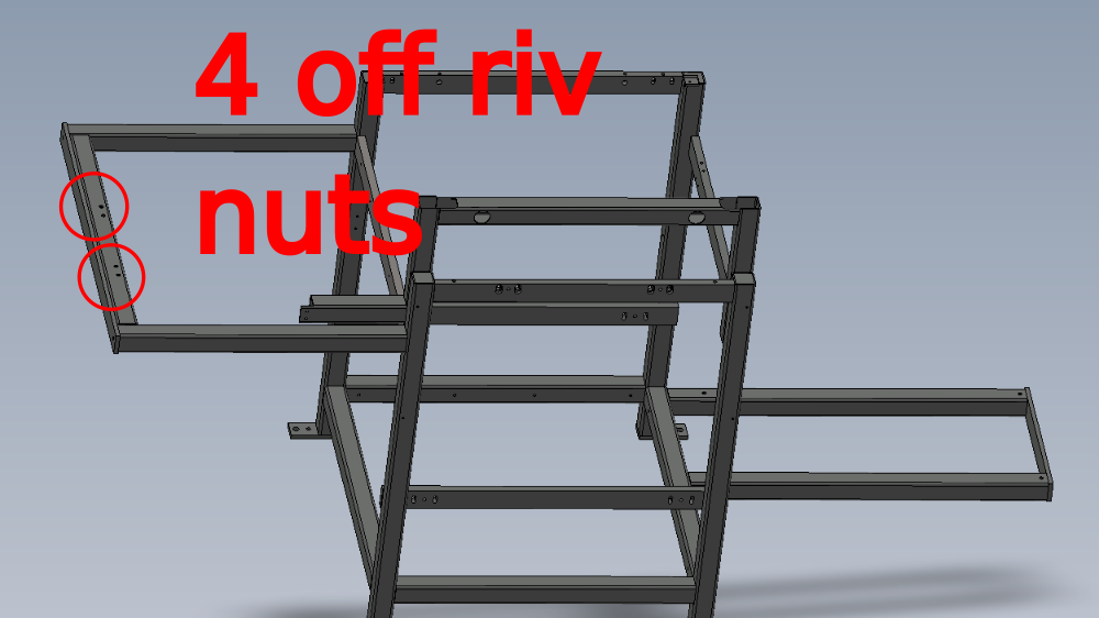
Étape 2 - M6 rivnuts
Check frame has M6 rivnuts installed
If not present install with riv nut applicator
Riv nuts must be flush with box section face

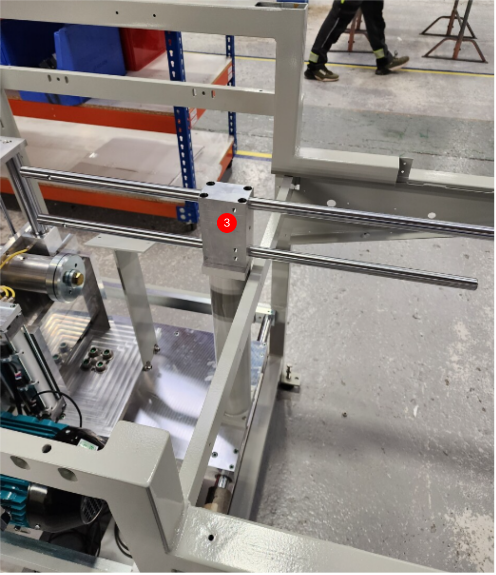
Étape 3 - Attach eject support
1 Grease eject support blocks
2 Assemble with pre built support block
3 Fix to frame with M6 x 60 socket caps . Do not use adhesive at this point
4 Check for smooth operation

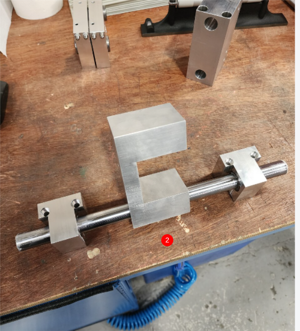
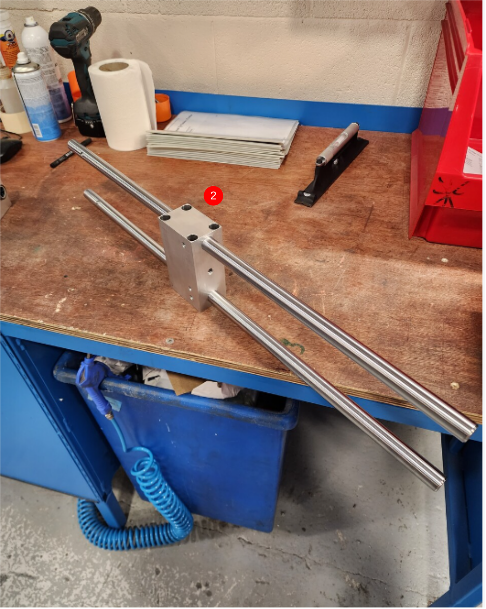
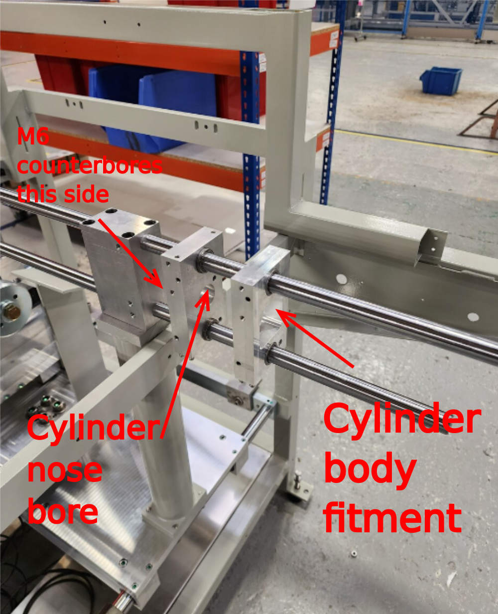
Étape 4 - Attach Rod base
1 Clean shafts with Fe solvent
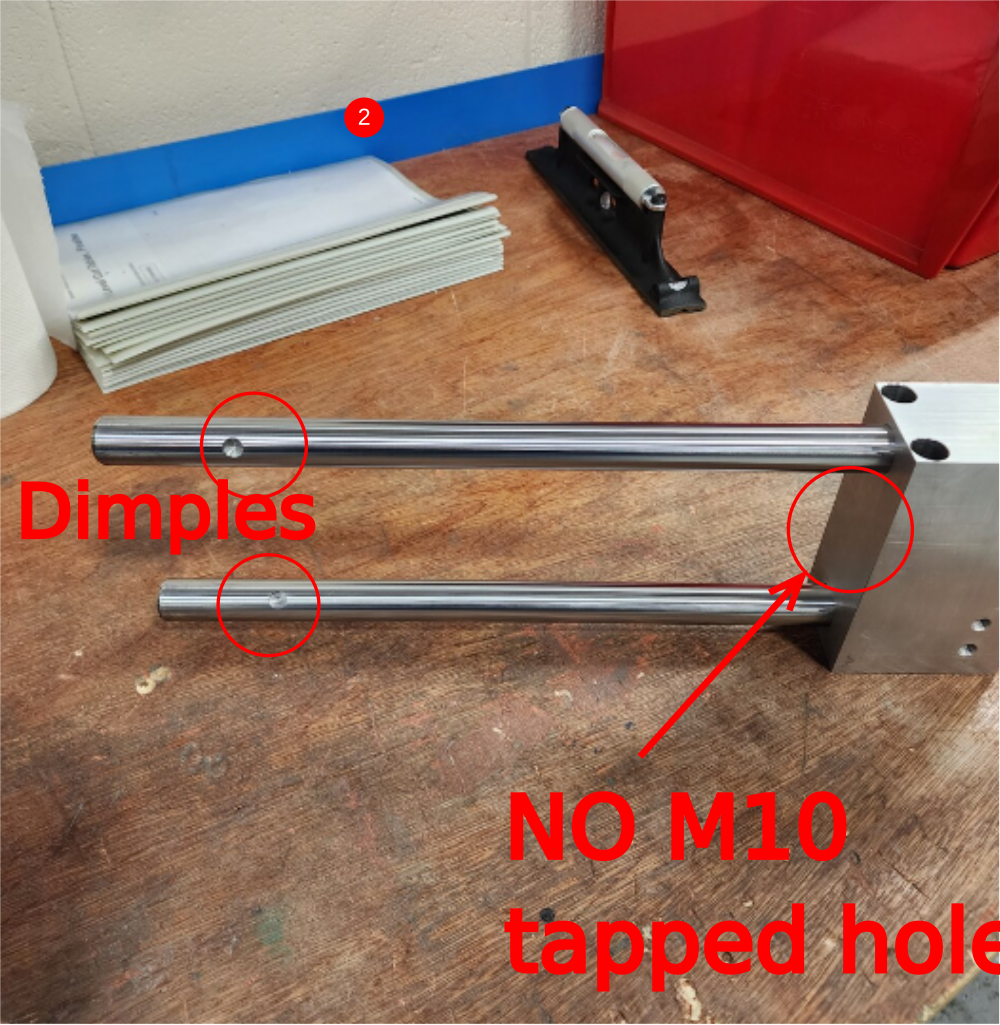
2 Insert shafts into rod base as shown , orientate dimples on shafts as shown in relation to rod base holes
3 Fix to eject support post as shown using M8 x 80 socket caps 4 off. Do not use adhesive

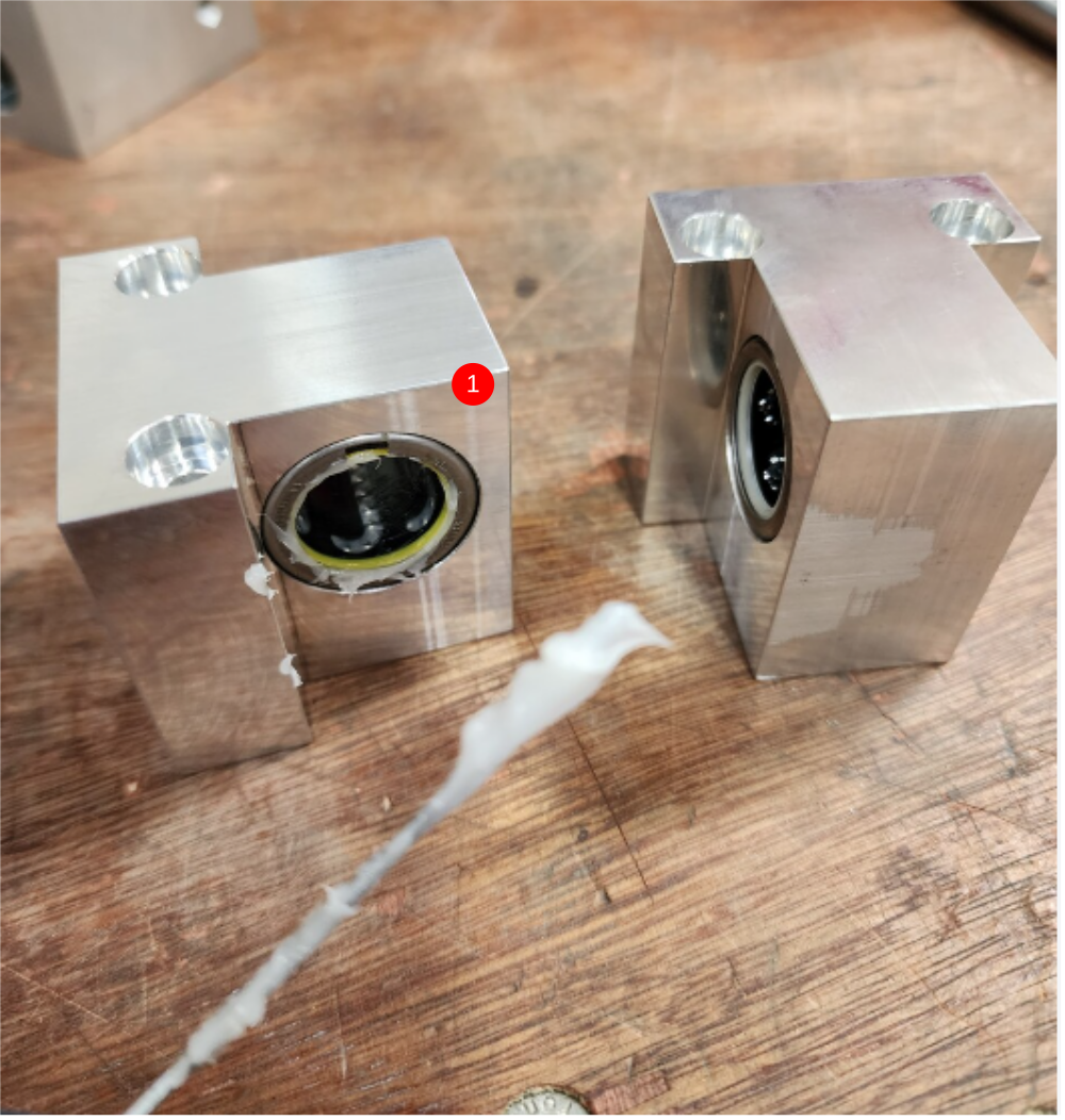
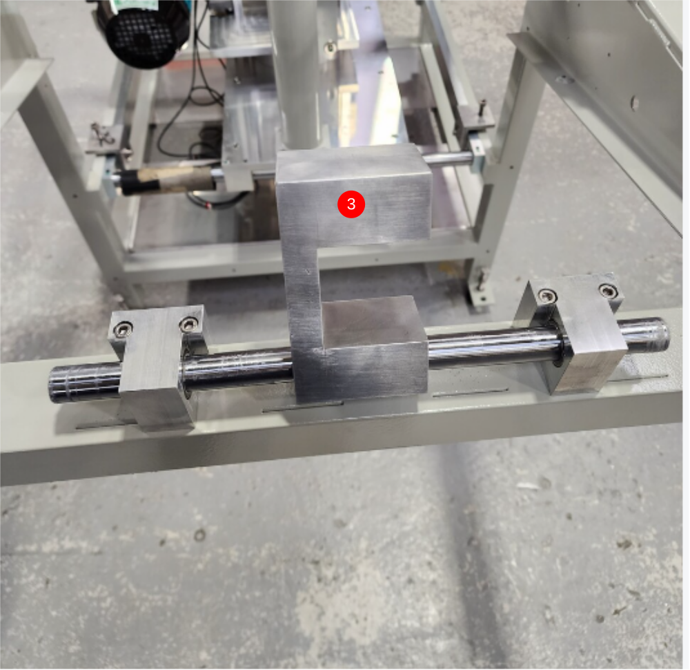
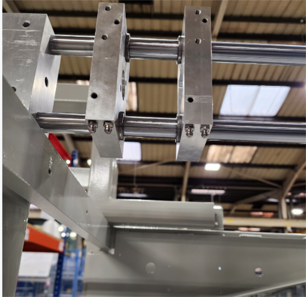
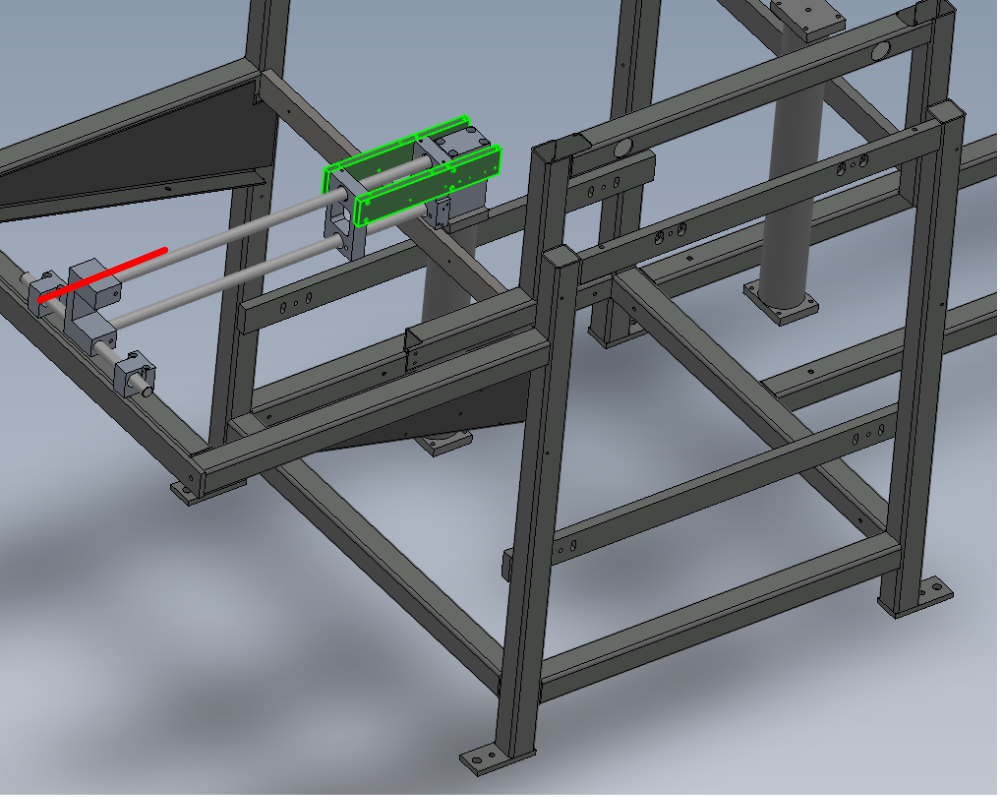
Étape 5 - Fit eject bearing blocks
Fit pre built bearing blocks to eject shafts
Ensure correct orientation as shown

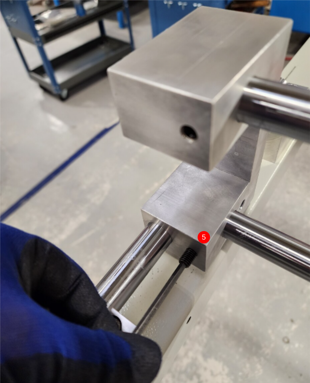
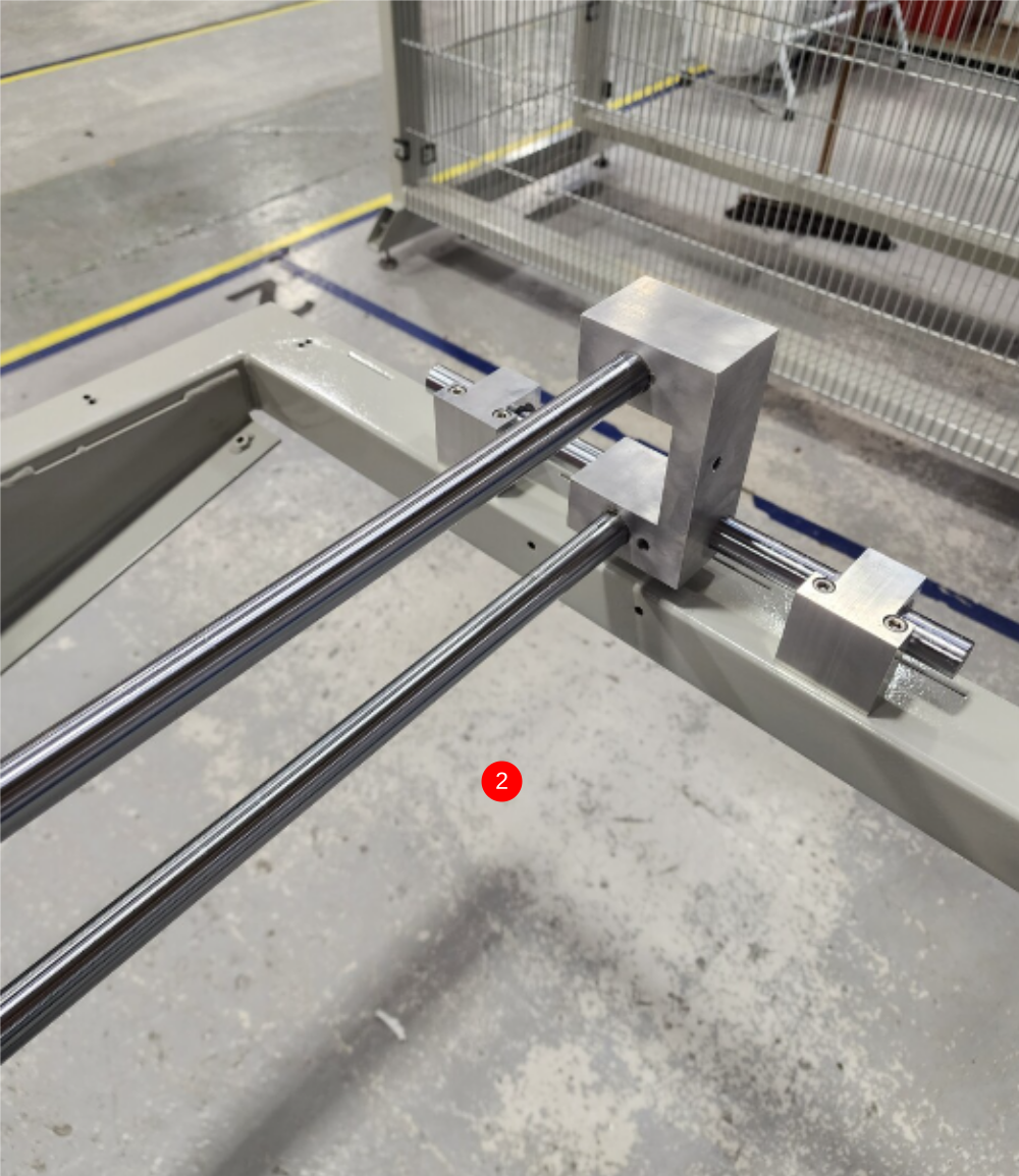
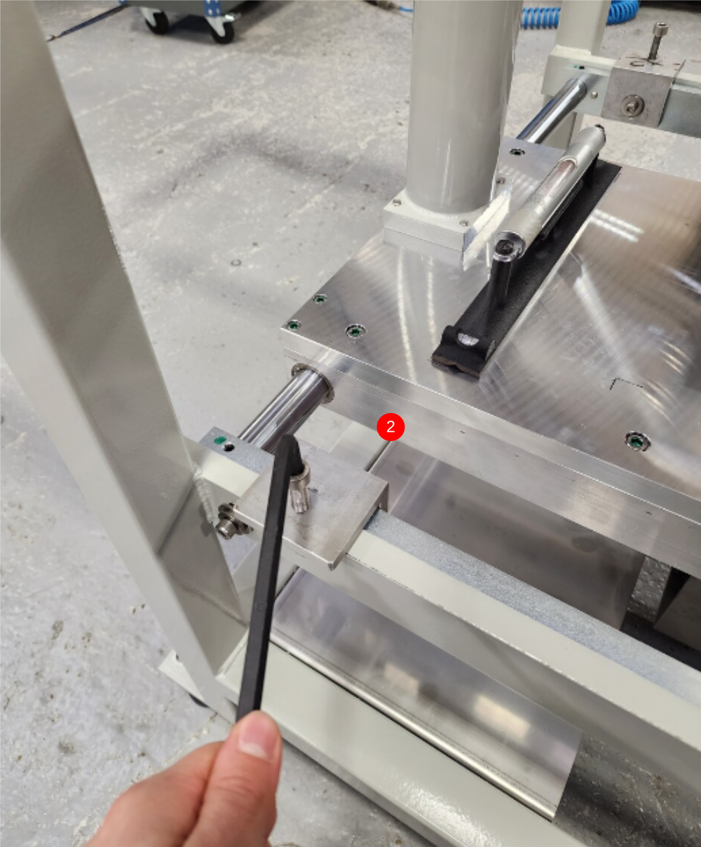
Étape 6 - position eject shafts
1 slide lower shaft into eject support block as shown , ensuring dimple aligned with M8 hole in rod base
2 Slide into position upper shaft ensuring dimple in shaft is aligned with rod base M8 hole
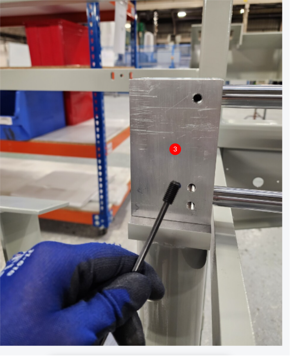
3 Add 2 off M8 x 16 kcp grubscrews to captivate shafts into rod base. Use loctite 243 on grubscrews
4 Apply medium pressure to fixings in rod base
5 Add 2 off M8 20 kcp grubscrews to eject support under light tension. Do not add adhesive

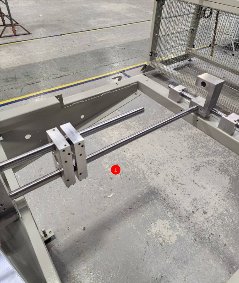
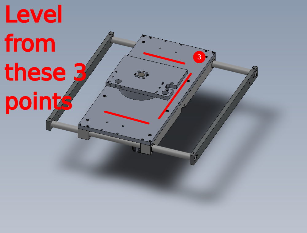
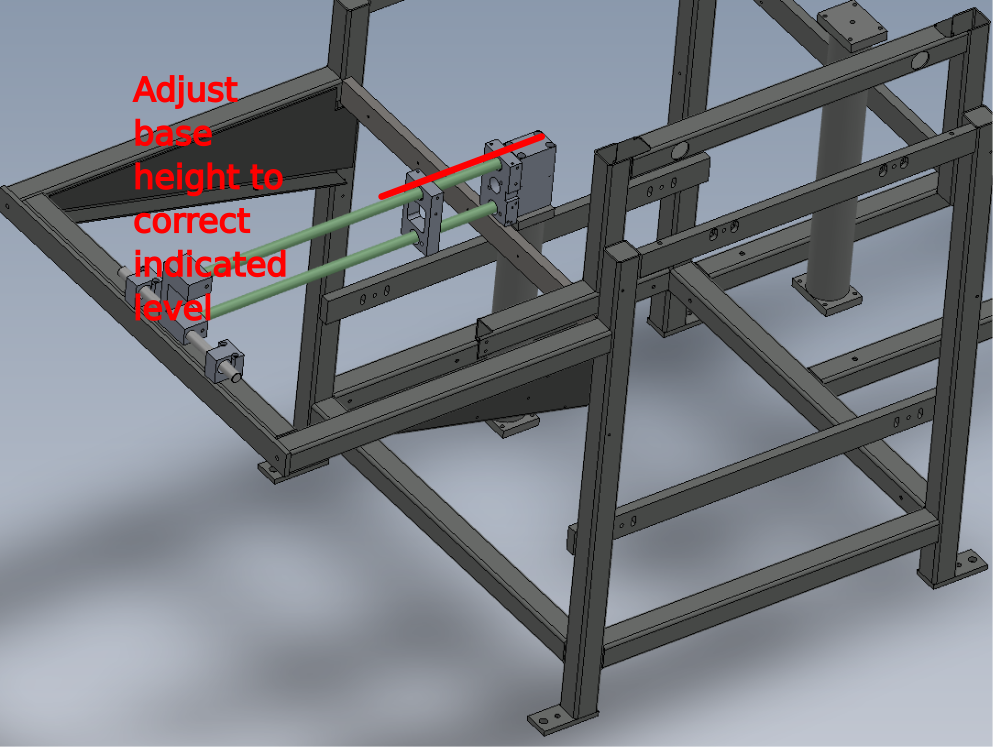
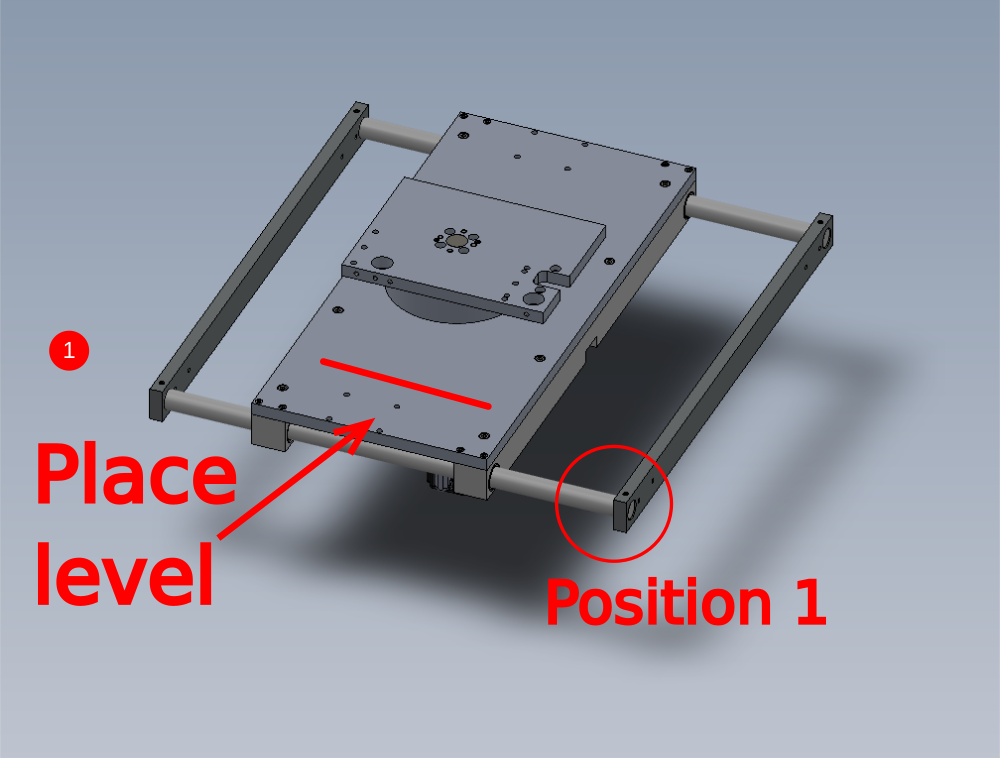
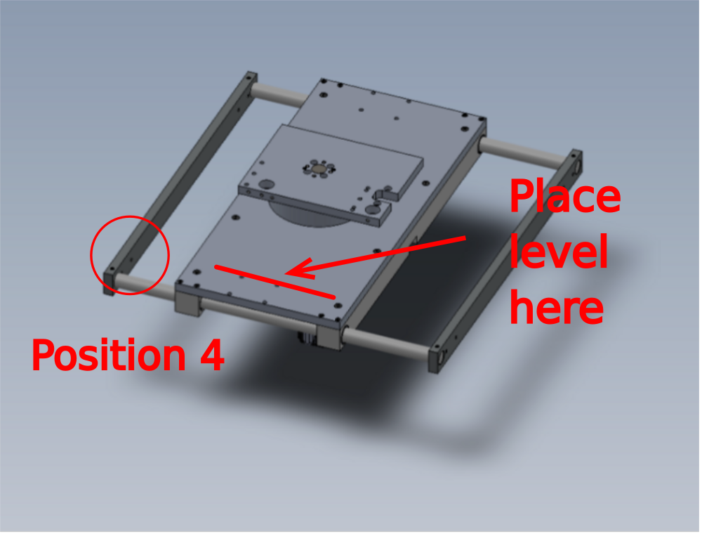
Étape 7 - Level base
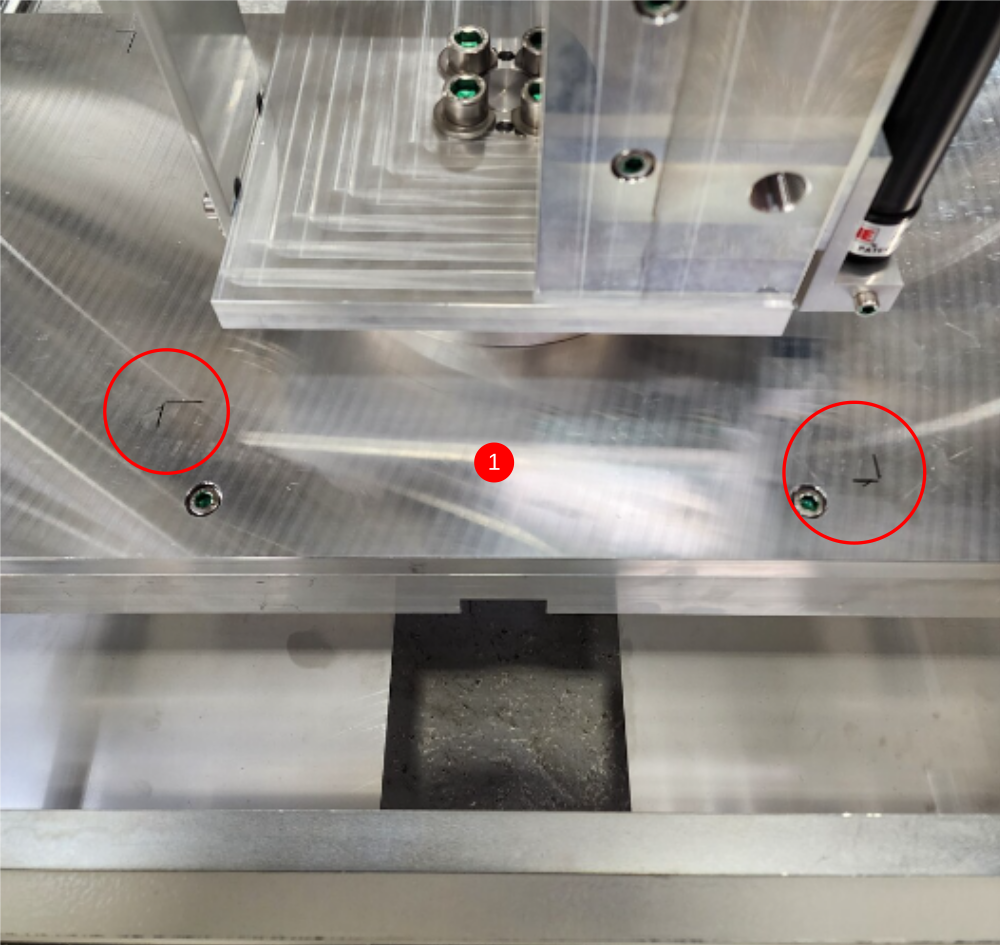
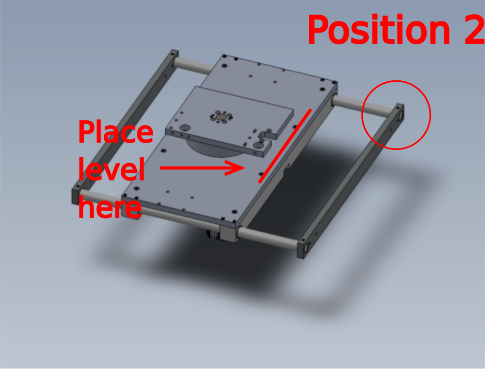
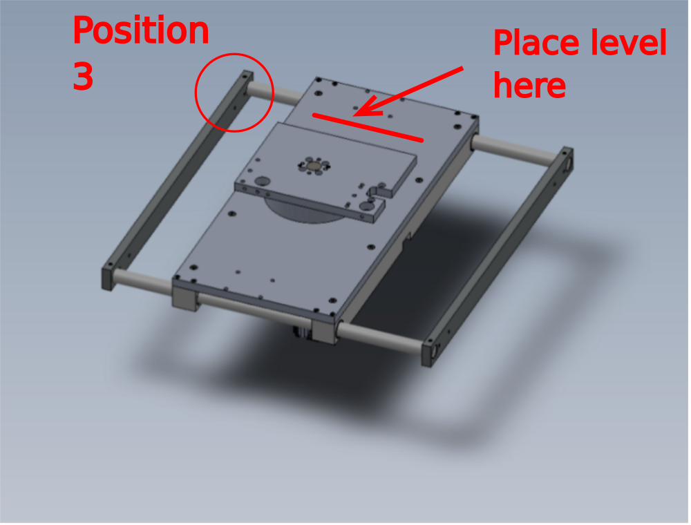
1 Use engineers level at indicated points to set base level. Use marker pen to outline level positions, so consistent point is used each time the level is moved to a new position
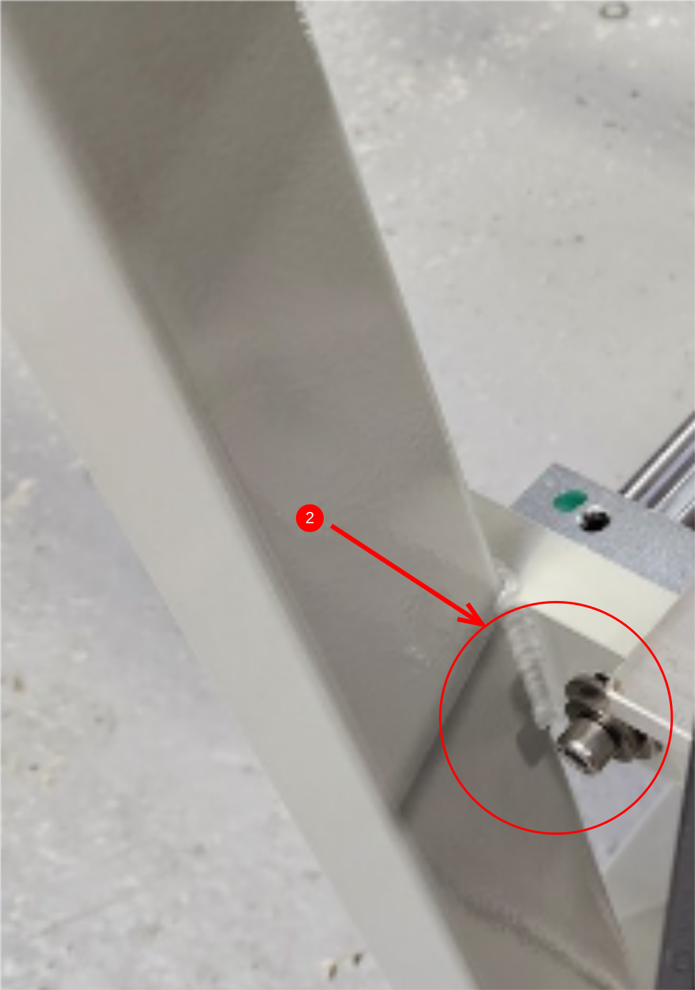
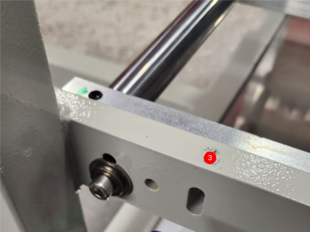
2 Adjust using jacking screws on support brackets
3 Ensure all 3 indicated points are set level

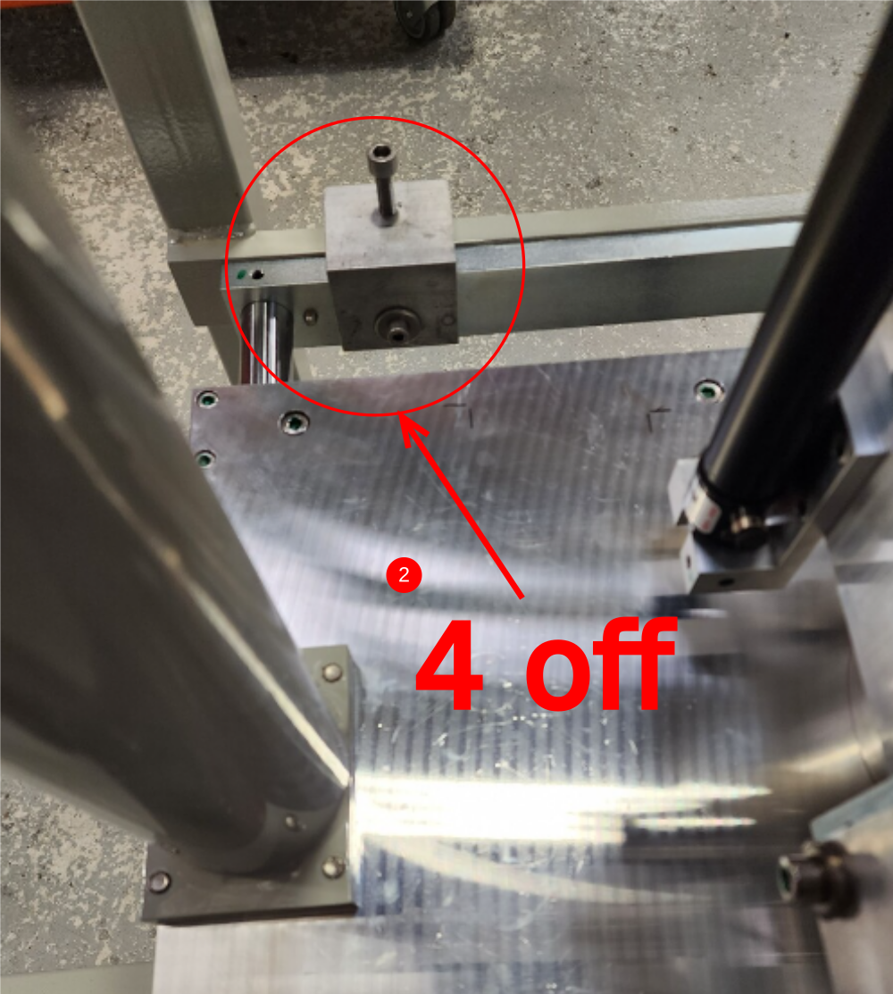

Étape 8 - Check end plate level
End block level should be checked for level and adjusted to be correct

Étape 9 - Level eject shafts
1 Use engineers level to check level of eject assembly at 3 points of movement.
2 Adjust base evenly to maintain base level , to adjust eject shafts level
3 Once correct height of base is achieved to set eject shafts level, and a discrepancy is noticeable on level of eject shafts at 3 positions , recheck previous step for being set level

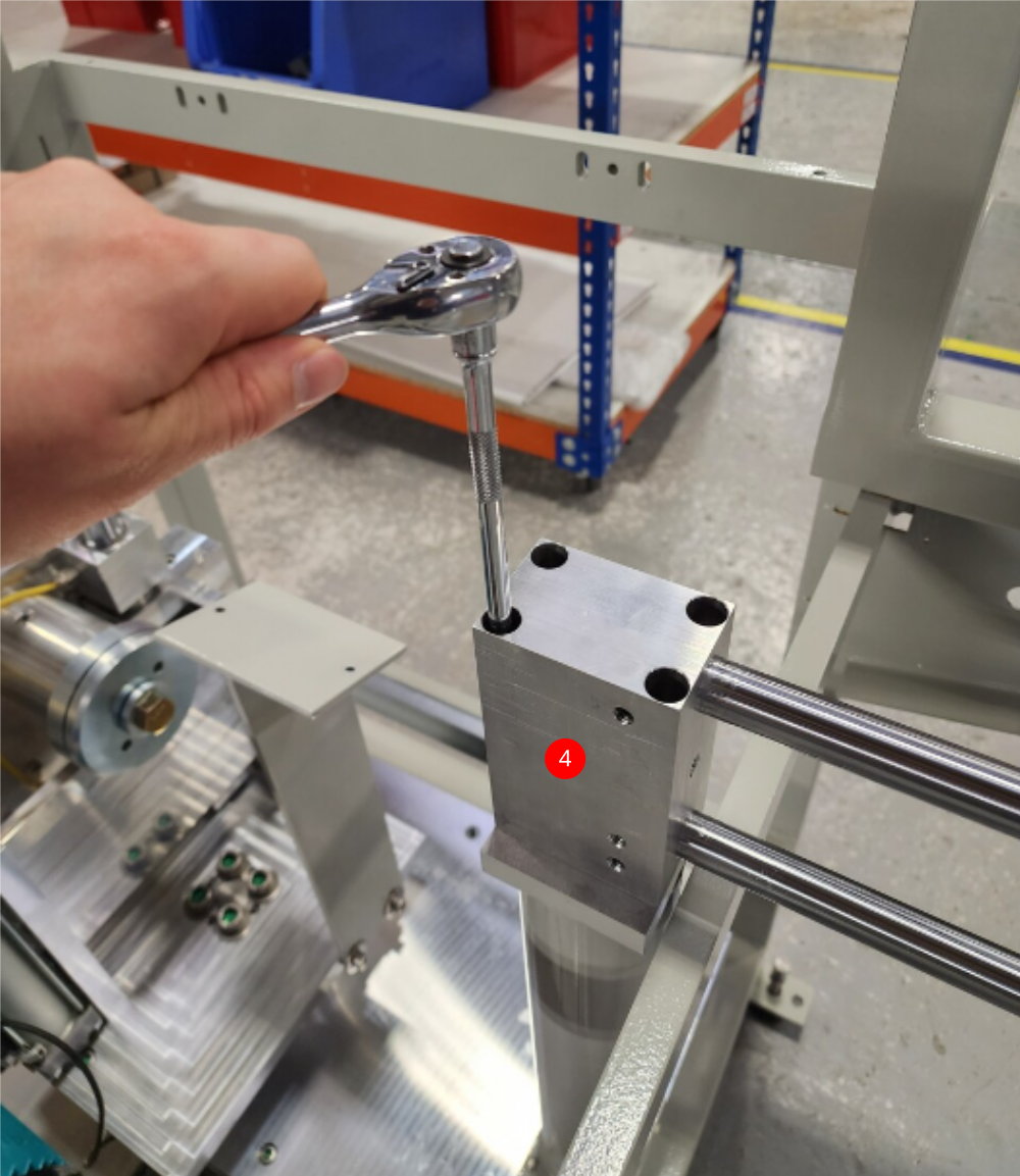
Étape 10 - Finalise Grubscrews
Finalise grubscrews in support block indivdually

Étape 11 - Fit ejector tie bars
Fit ejector tie bars to ejector bearing blocks, using 8 off M6 x 25 set bolts and A form washers . Only apply light tension and do not use adhesive


Étape 12 - Finalise position of base Point 1
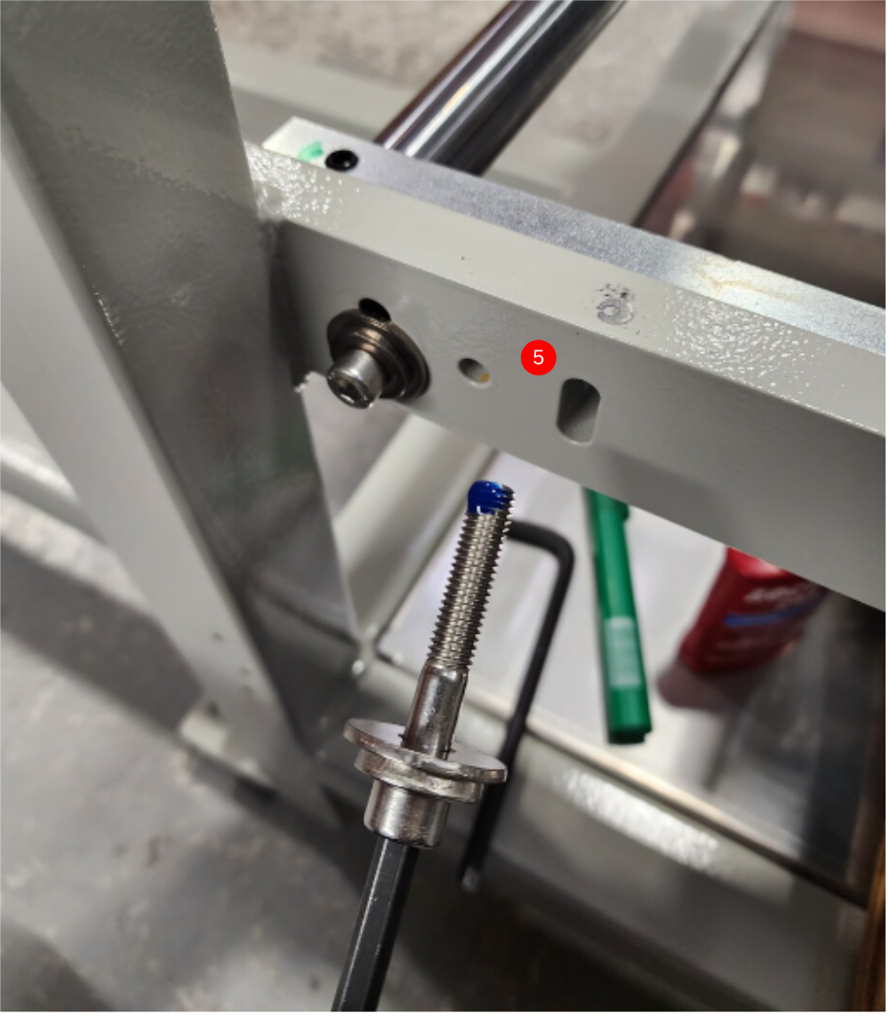
Adjusting brackets should be removed individually once all settings are complete
1 Place level on base on marked points to use to identify if base moves position when final tension to holding bolts is added
2 Add final tension to fitted M8 socket cap
3 Remove Support bracket
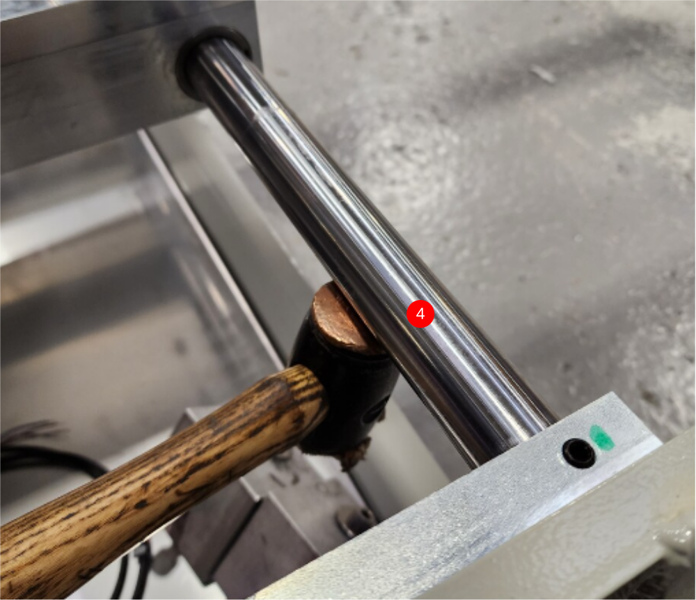
4 Adjust level if moved. Use copper hammer to impact shaft in direction required to adjust level
5 Add and finalise M8 socket cap with same washer configuration as previous fitted M8
6 Remove first M8 fastener, add Loctite 243 and add final tension
7 Adjust height again using step 4 if level indicates movement has occurred when fitting second fastener
Étape 13 - Finalise position of base Point 2
Repeat step 11 at these points
Étape 14 - Finalise position of base Point 2
Repeat step 11 at these points
Étape 15 - Finalise position of base Point 2
Repeat step 11 at these points
Étape 16 - Check all settings
Recheck all previous settings stated in this procedure, and ensure all have met and retained specified settings
Supervisor sign off required
Draft
 Français
 English
 Deutsch
 Español
 Italiano
 Português