This Dokit will provide step by step instructions on how to retrofit home and out sensors to the eject push bar on ZX machines.


Difficulté
Moyen
Durée
30 minute(s)
Sommaire
- 1 Introduction
- 2 Étape 1 - Check Parts
- 3 Étape 2 - Prep Work
- 4 Étape 3 - Turn Off the Machine
- 5 Étape 4 - Fitting the Reed Switches
- 6 Étape 5 - Fitting the m8 Cables
- 7 Étape 6 - Adding the Plug Join
- 8 Étape 7 - Wiring the m8 Cables
- 9 Étape 8 - Setting the Sensors
- 10 Étape 9 - Software Changes - IODEF file
- 11 Étape 10 - Software Changes - params.saw
- 12 Étape 11 - Mapping IO to Twincat and Update configuration
- 13 Étape 12 - Add the Alarms
- 14 Commentaires
Introduction
The Eject Push bar on the Saw Outfeed on the ZX machines does not have sensors fitted to monitor the position of the cylinders. This causes an issue when the bar is obstructed and either does not fully extend or not fully extract. The cycle is not aware of the position of the cylinders and the machine will continue to run, often resulting in a collision. Not having sensors fitted also means that the Eject Push cycle is run via a timer. However, using a timer means that the system does not know the actual position of the cylinders. Having sensors fitted to the cylinders will allow us to have a cycle that monitors the position of the cylinders and we can determine the cycle has finished before allowing another operation to proceed. We can also use the sensors as feedback to stop the machine if the cycle fails. This will result in fewer collisions and damage to parts or products.
Attention
Utiliser des chaussures de protection
Haute Tension
Étape 1 - Check Parts
A retrofit kit will be sent with all the parts needed to carry out this task.
The assembly number for the kit is R0019218. If you have any feedback regarding this kit, please use this assembly number.
It is important to check the parts you have received against the assembly list to ensure you have nothing missing before starting the job.


Étape 2 - Prep Work
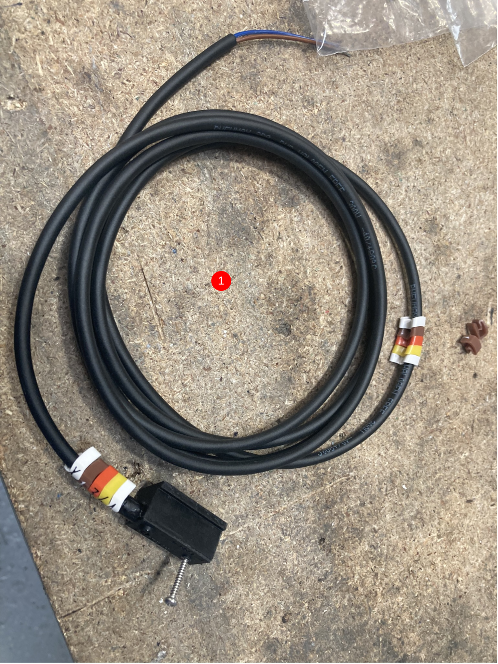
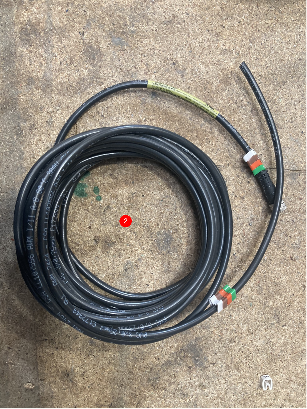
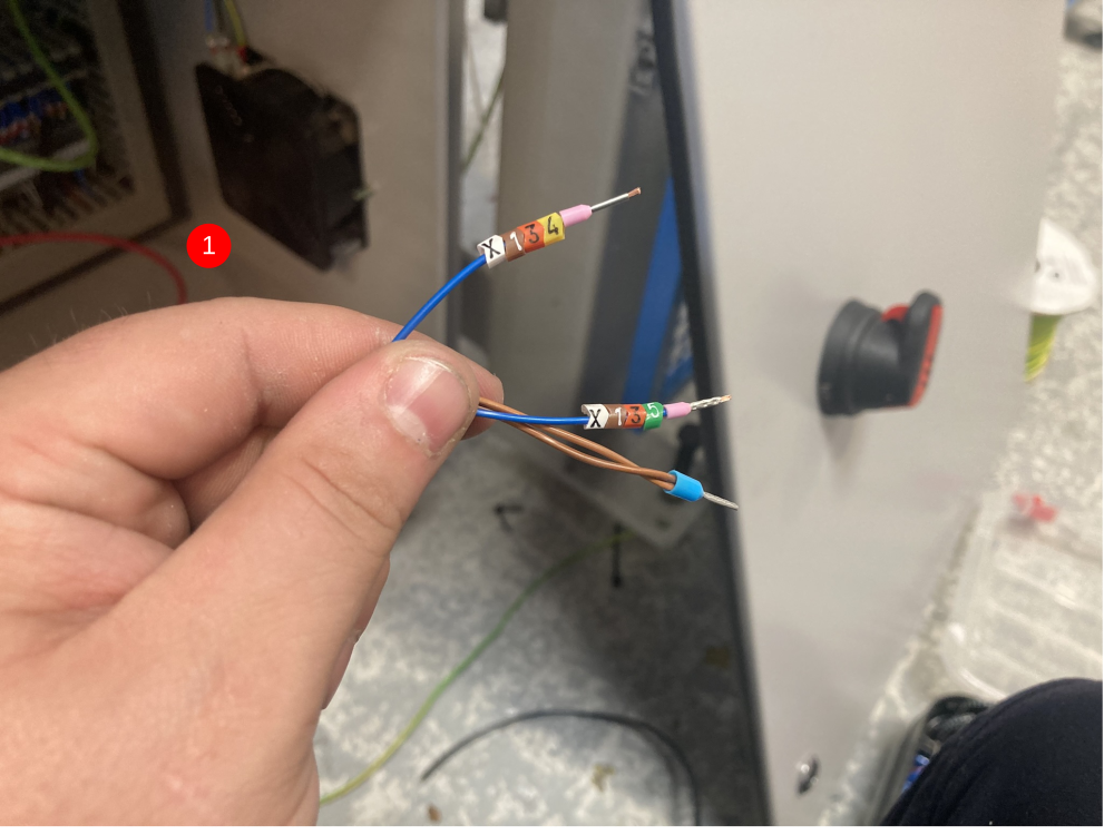
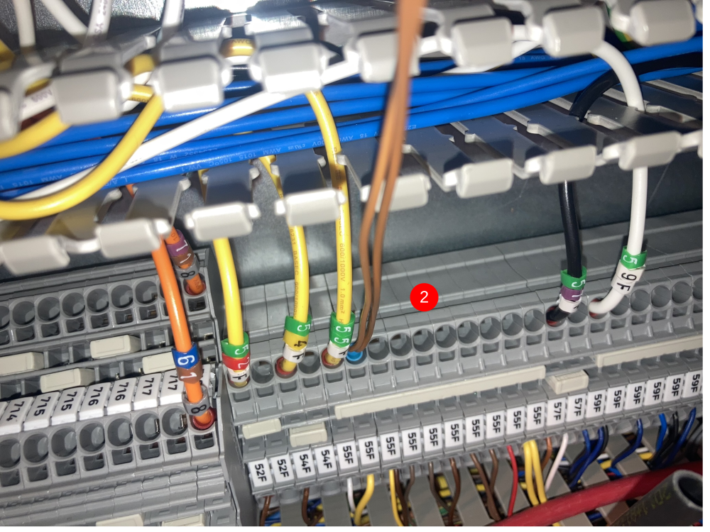
1; Add cable numbers to reed switch leads and m8 5m lead (pictures 1&2)
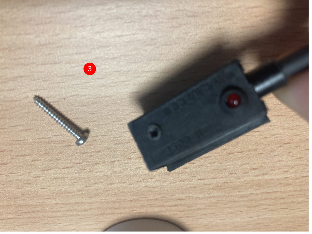
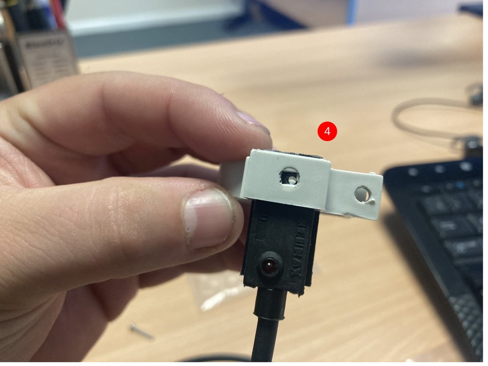
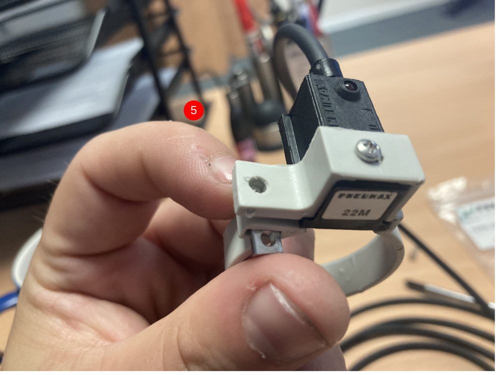
2; Fit reed switches into the cylinder bands (picture 3,4&5)
*At this stage, do not tighten the reed switches fully into the bands as this will make fitting the bands more difficult later.
Étape 3 - Turn Off the Machine
Étape 4 - Fitting the Reed Switches
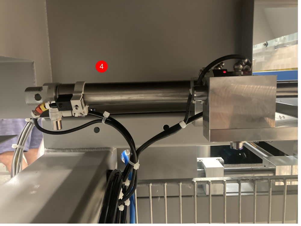
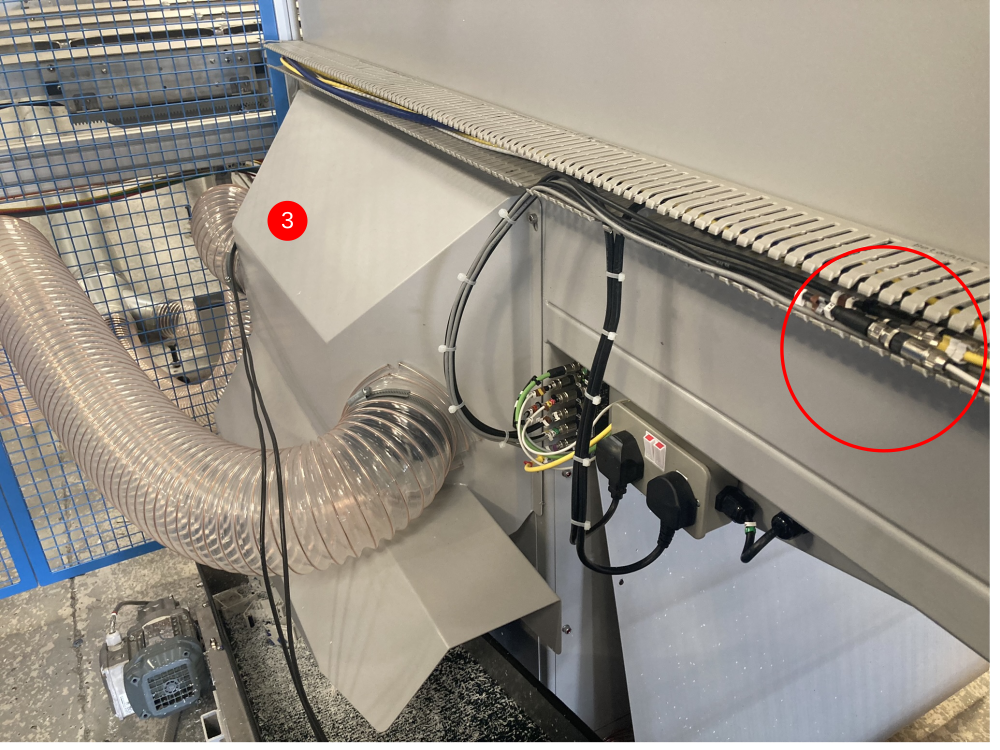
The sensors need to be fitted to the Eject Push cylinder that is closest to the Sawing Centre (picture 1 was taken on a ZX5 L>R feed).
The Eject Push assembly is surrounded by moving parts and therefore the sensors need to be fitted so that they remain out of danger.
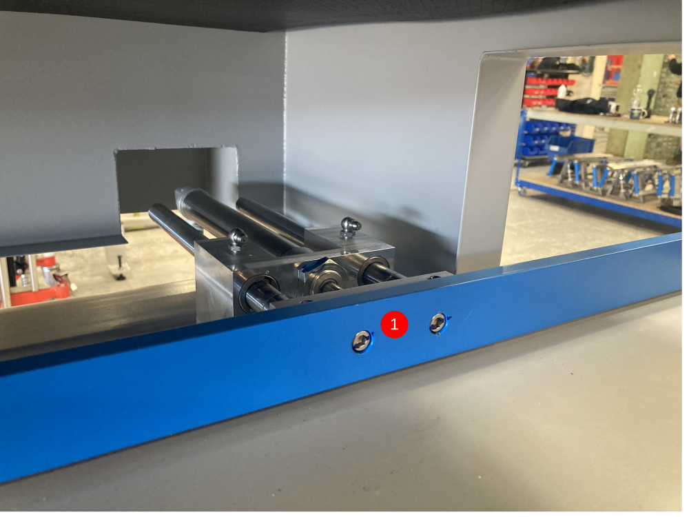
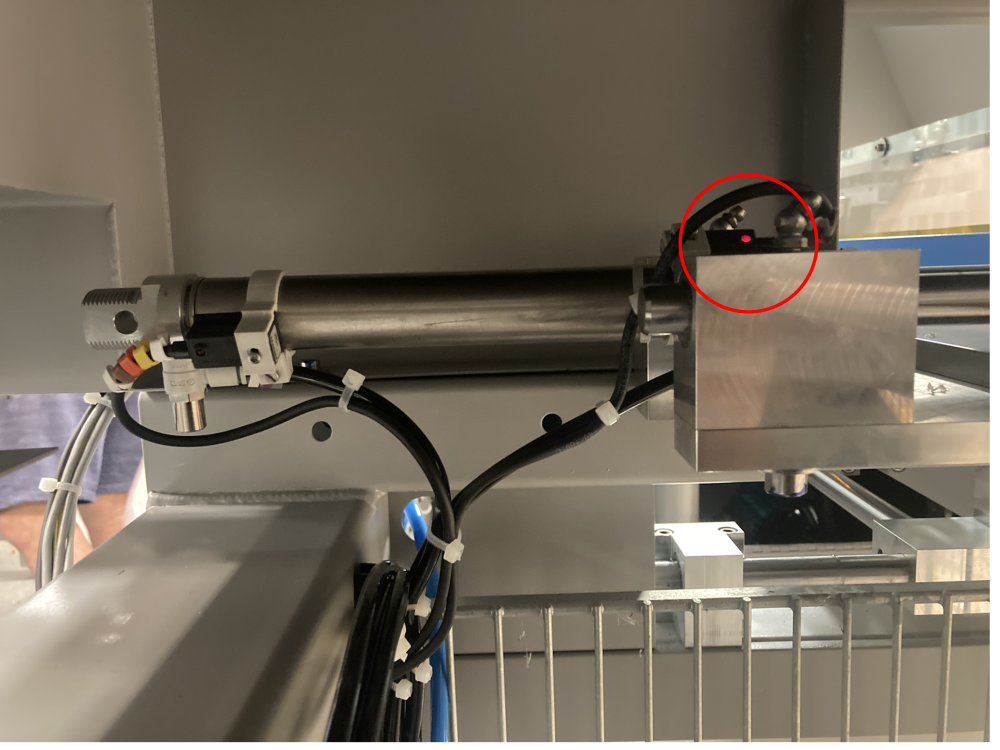
Sensor X134A is for InF_EjPushHm and needs to sense when the Eject Push bar is retracted. This sensor needs to be mounted at the rear of the cylinder (as shown in picture 2)
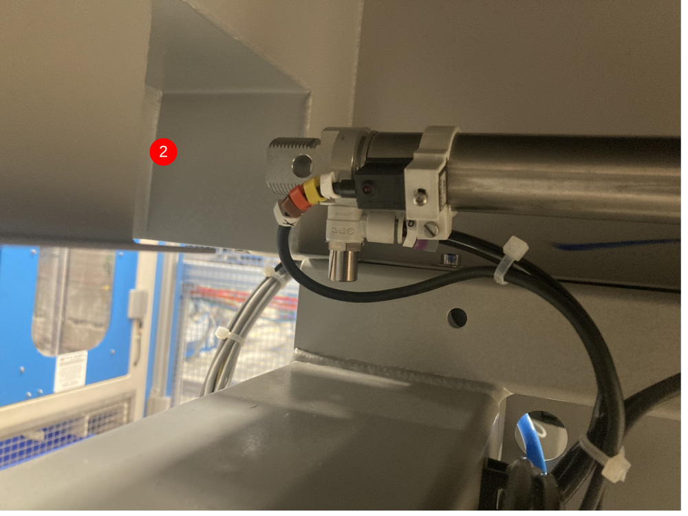
Sensor X135A is for InF_EjPushOu and needs to sense when the Eject Push bar is extended. This sensor needs to be mounted at the nose of the cylinder (as shown in picture 3). This sensor is in a vulnerable position and needs to be cable tied to the cylinder to make sure it remains safe from moving shafts.
At this stage the sensors will not be set in their final position (this will be done when the power is back on).
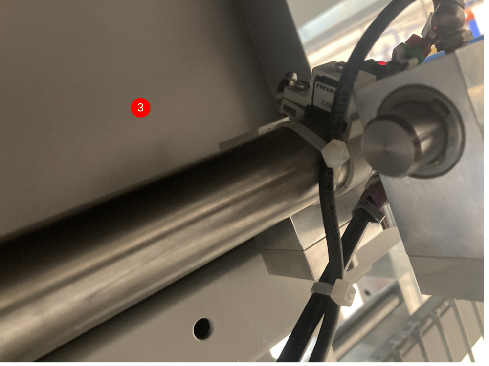
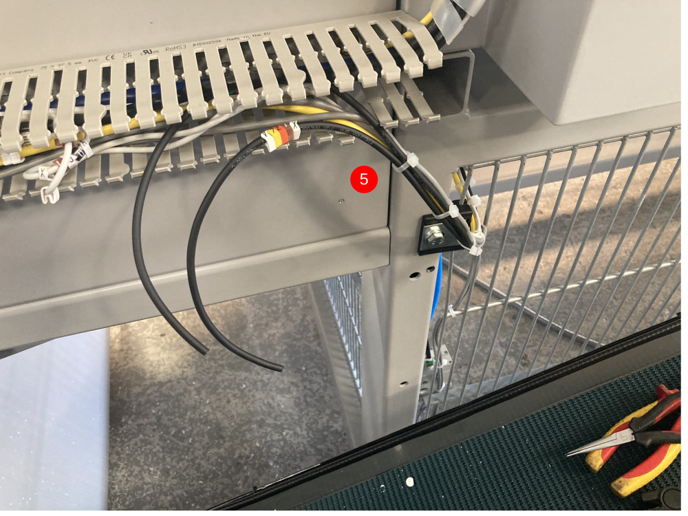
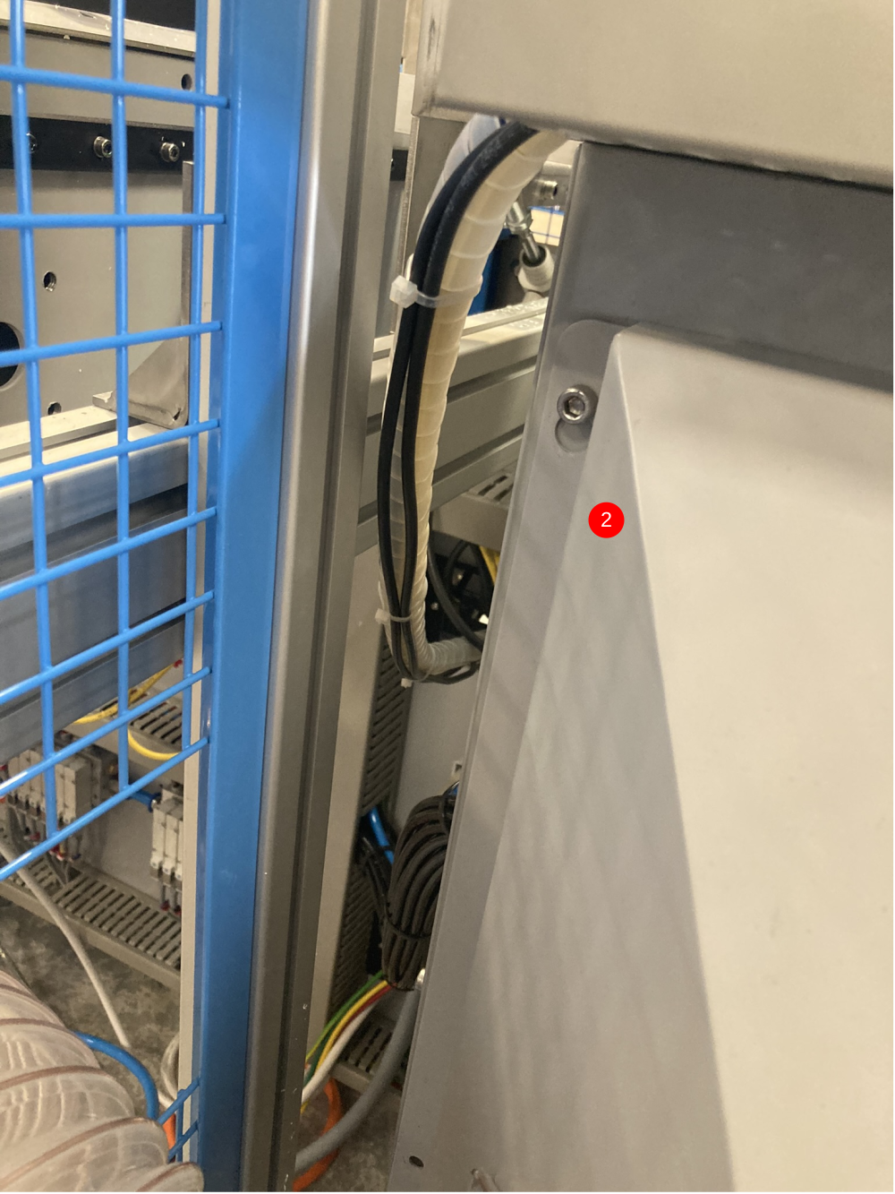
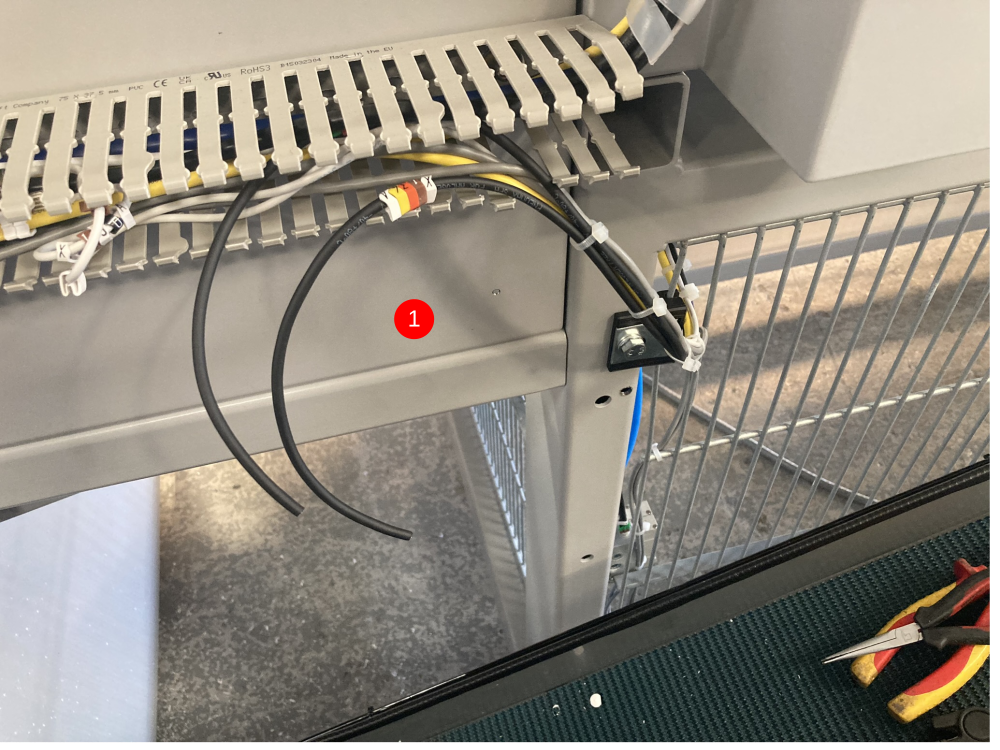
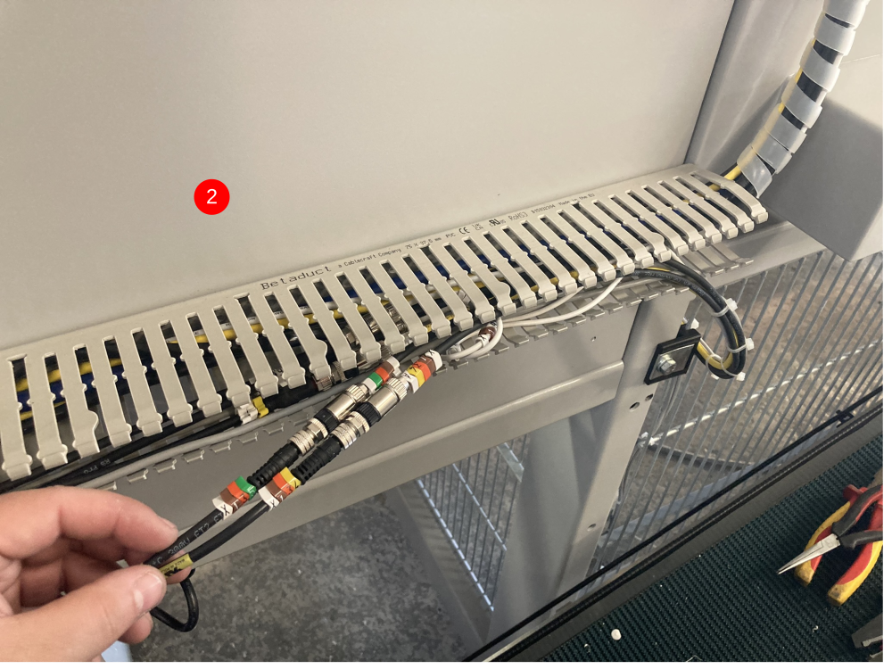
Both reed switches can then be cable tied along with the other Outfeed table cables and into the trunking on the rear of the Sawing Centre (as shown in pictures 4&5)
Étape 5 - Fitting the m8 Cables
The m8 cables will be joined to the reed switch cables. They act as an extension to the reed switches as the reed switches are not long enough to go back to the cabinet.
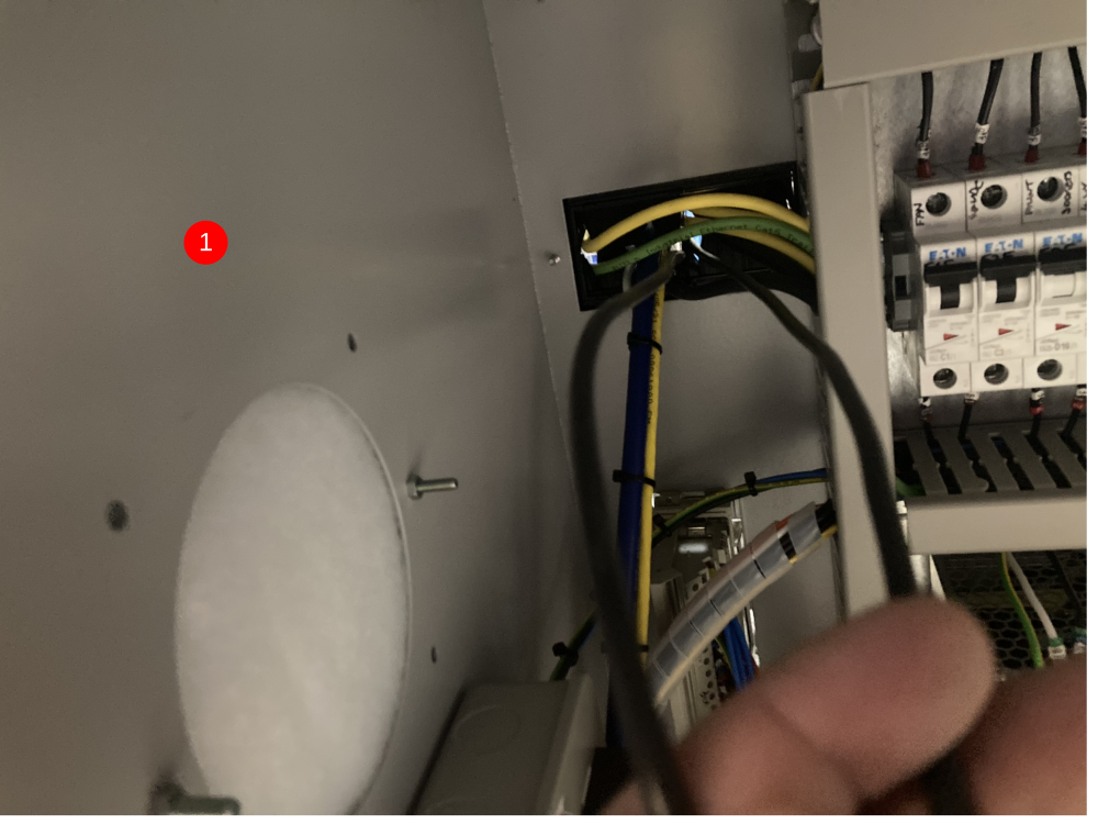
The m8 cables need to be fed through the top brush strip in the rear of the Sawing Centre electrical cabinet (as shown in picture 1). They then run up with the console cables, into the trunking on the rear of the Sawing Centre (as show in picture 2). The m8 ends need to be sat with the other m8 cables that are joined in the trunking (as shown in picture 3).
Étape 6 - Adding the Plug Join
Now the sensors are in the rear trunking, they need to be cut roughly the same length as the other cables that are joined (as show in picture 1).
A dedicated Dokit has been created on how to wire the m8 plugs. A link to that Dokit can be found below:
Fitting M8 Plug for EtherCAT Boxes
Once the plugs have been fitted to the cables, you can plug in the m8 cables (as shown in picture 2). The trunking lid can then be refitted.
Étape 7 - Wiring the m8 Cables
Now that the cables are run through the trunking and joined to the reed switches, they need to be wired into the electrical cabinet.
Each cable has 2 cores (brown and blue), the brown core on each cable needs to go to 55F (24Vdc) and the blue cores are used as an input back into the PLC and they will need to be terminated in the IO slices in the cabinet.
Cut the cables so they are long enough to reach the longest point. Strip them back, exposing the 2 cores. The blue cores need to be numbered (same as cable number) and then individually crimped with bootlace crimps. The brown wires can be crimped together as they both terminate in the same place (as shown in picture 1).
The brown wires will terminate into the 55F common rail (as shown in picture 2).
The blue wire labelled X134 goes into the third IO slice (MC4F), terminal 4. The blue wire labelled X135 goes into the third IO slice (MC4F), terminal 5 (as shown in picture 3).
Once the cores are wired in, any trunking lids that were removed need to be refitted and any offcuts of cables disposed of.

Étape 8 - Setting the Sensors
Once power has been put back on the machine, the sensors can be set.
The X134A sensor needs to light up 'red' when the Eject Push bar is in its retracted position. Make sure the bar is all the way back and then adjust the reed switch up or down the cylinder until the red light comes on. When it comes on, tighten the sensor into place. The same needs to be repeated on X135A but the bar needs to be in its extended position.
Once the sensors have been set using the light on the reed switch, you need to make sure that the lights on the IO slice come on and off in each position.
Étape 9 - Software Changes - IODEF file
The following lines need to be checked in the IODef file:
*the IODef file may already have these lines but the fields will need to be updated to match the lines below*
InF_EjPushH,134,1,0,0,False,False,53,7,-,False,0,134
InF_EjPushO,135,1,0,0,False,False,53,8,-,False,0,135
Étape 10 - Software Changes - params.saw
Set the following parameters in the params.saw, or via settings screen
useEjectHome=1
useEjectOut=1
Étape 11 - Mapping IO to Twincat and Update configuration
This requires a Dial in and Support.
1 Ensure correct project is being used - if Ensure ask for help.
2. Map both inputs 134 and 135 to Ethercat Unit MC5F Last input slice
134 to terminal 3
135 to terminal 4
As shown in photo
Activate the Configuration.
Check back in RUN mode

Étape 12 - Add the Alarms
Draft
 Français
 English
 Deutsch
 Español
 Italiano
 Português