This document will provide the relevant instructions on how to add a safety contactor for the 3 phase power going to the Beckhoff AX8000 series drives on the Stuga Machines.

Difficulté
Facile
Durée
15 minute(s)
Attention
Consulter le manuel d'instructions
Pour l'entretien, débranchez l'appareil du secteur
Haute Tension
Étape 1 - Fitting Contactor
Find a spare section of DIN rail that the contactor can be placed in. The contactor clips onto the din rail without the need for fixings.

Étape 2 - Removing Current Wiring
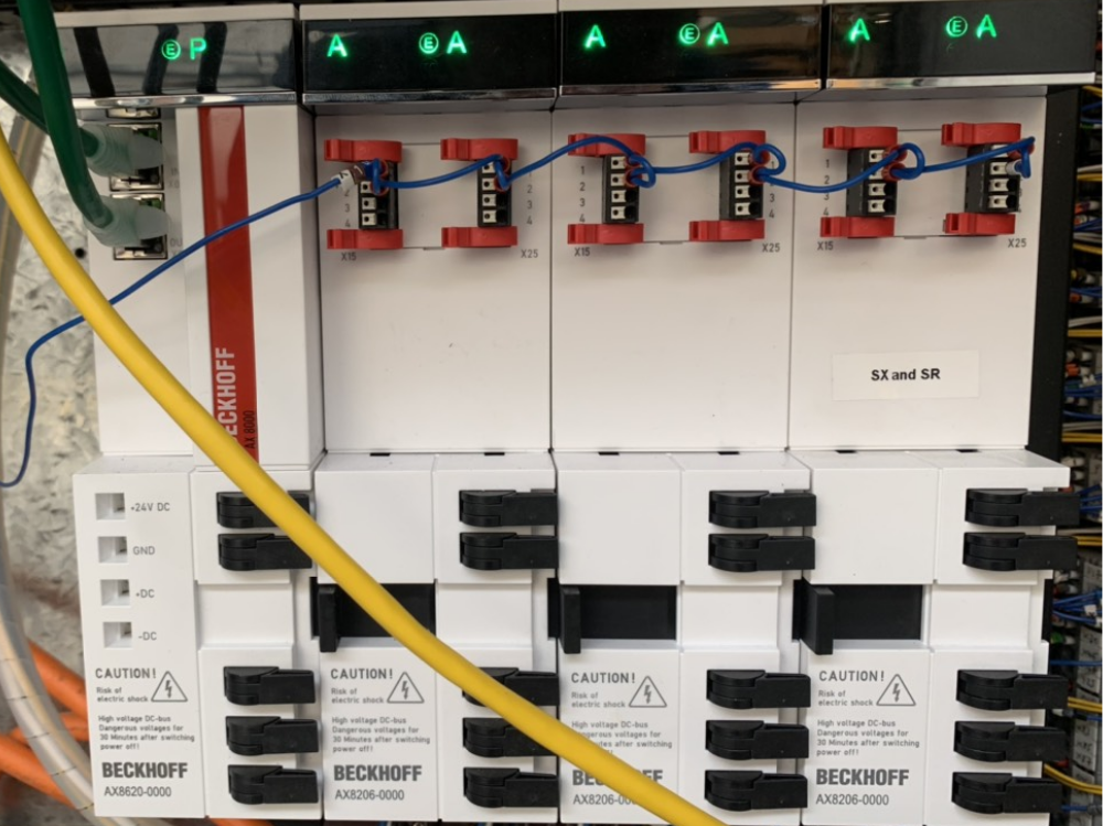
On the bottom of the AX8000 servo drives. There is a plug that has all of the supply wiring going to it. The wires that are terminated into L1, L2 L3/N need to be removed and placed into the newly added contactor as follows:
The wire that was in L1 goes into 13NO on the contactor.
The wire that was in L2 goes into 33NO on the contactor.
The wire that was in L3/N goes into 43NO on the contactor.

Étape 3 - Adding Mains Wires in Contactor
Now we need to add 3 wires to go from the contactor, to the AX8000 drives. You will have received some 1mm black wire for this.
The new wiring is as follows:
Wire 1 wires into 14NO in the contactor and then L1 on the AX8000 plug.
Wire 2 wires into 34NO in the contactor and then L2 on the AX8000 plug.
Wire 3 wires into 44NO in the contactor and then l3/N on the AX8000 plug.
Once this is done, the mains power to the drive is complete. The next step is wiring the coil of the contactor.
Étape 4 - Contactor Coil Wiring
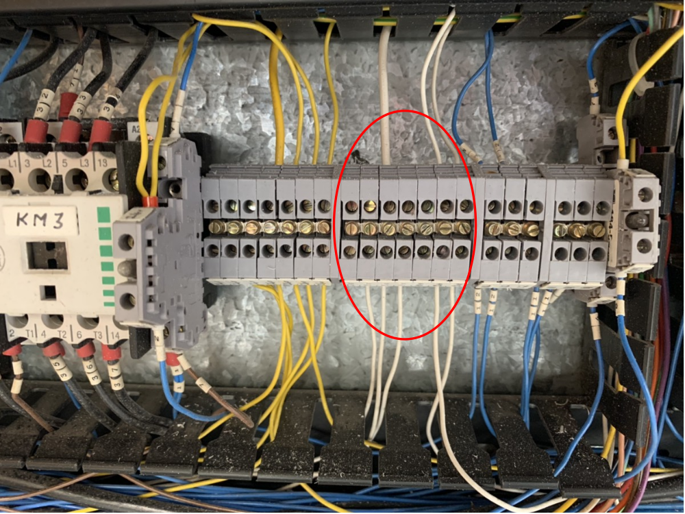
We have wired the mains into the contactor but we have not done the wiring to make the contactor come on and off when an ESTOP is pressed. To do this, you first need to find a 0V wire in the cabinet (white wire). Picture 1 shows where to find a 0V in the cabinet. Add a wire into any spare 0V terminal and then wire it into A2 on the contactor.
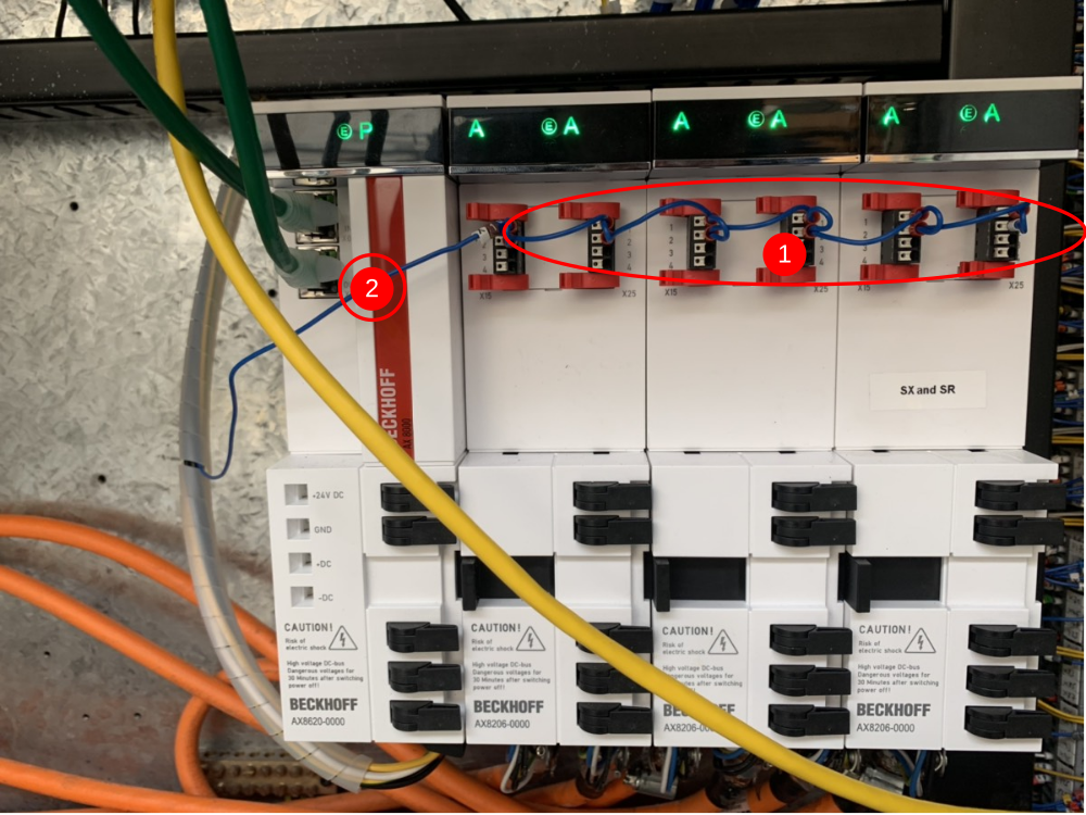
You then need to remove the wires that go across the front of the drives (marked 1 in the picture). This wire will be the A1 in the contactor. The wires that go across the front of the drive are all linked together, however, you will notice that they all start from 1 wire (marked 2 in the picture). It is only the wire marked 2 that we need. This means that all of the little links can be cut off and binned.
Étape 5 - Testing
The machine can now be turned back on. When the machine is back on, you will notice that the drives remain off. Press the alarm reset button to bring the air into the machine and then the drives should power on.
Job is complete.
Published
 Français
 English
 Deutsch
 Español
 Italiano
 Português