This Dokit will provide step by step instructions on how to retrofit home and out sensors to the eject push bar on ZX machines.

Difficulté
Moyen
Durée
30 minute(s)
Introduction
The Eject Push bar on the Saw Outfeed on the ZX machines does not have sensors fitted to monitor the position of the cylinders. This causes an issue when the bar is obstructed and either does not fully extend or not fully extract. The cycle is not aware of the position of the cylinders and the machine will continue to run, often resulting in a collision. Not having sensors fitted also means that the Eject Push cycle is run via a timer. However, using a timer means that the system does not know the actual position of the cylinders. Having sensors fitted to the cylinders will allow us to have a cycle that monitors the position of the cylinders and we can determine the cycle has finished before allowing another operation to proceed. We can also use the sensors as feedback to stop the machine if the cycle fails. This will result in fewer collisions and damage to parts or products.
Attention
Utiliser des chaussures de protection
Haute Tension
Étape 1 - Check Parts
A retrofit kit will be sent with all the parts needed to carry out this task.
The assembly number for the kit is R0019218. If you have any feedback regarding this kit, please use this assembly number.
It is important to check the parts you have received against the assembly list to ensure you have nothing missing before starting the job.
Étape 2 - Prep Work
1; Add cable numbers to reed switch leads and m8 5m lead (picture ???)
2; Fit reed switches into the cylinder bands (picture ???)
*At this stage, do not tighten the reed switches fully into the bands as this will make fitting the bands more difficult later.
Étape 3 - Turn Off the Machine
Étape 4 - Fitting the Reed Switches
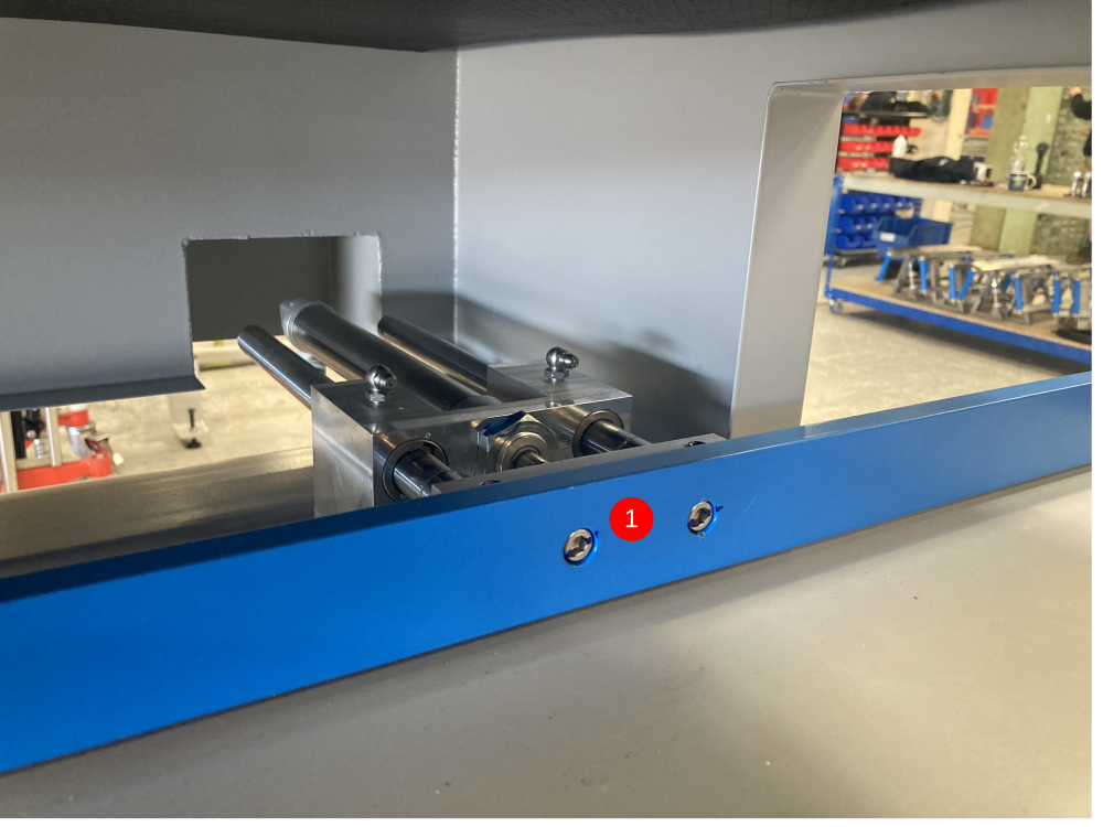
The sensors need to be fitted to the Eject Push cylinder that is closest to the Sawing Centre (picture 1 was taken on a ZX5 L>R feed.
The Eject Push assembly is surrounded by moving parts and therefore the sensors need to be fitted so that they remain out of danger.
Sensor X134A is for InF_EjPushHm and needs to send when the Eject Push bar is retracted. This sensor needs to be mounted at the rear of the cylinder (as shown in picture ???)
Sensor X135A is for InF_EjPushOu and needs to sense when the Eject Push bar is extended. This sensor needs to be mounted at the nose of the cylinder (as shown in picture ???). This sensor is in a vulnerable position and needs to be cable tied to the cylinder to make sure it remains safe from moving shafts (as shown in picture ???).
At this stage the sensors will not be set in their final position (these
Both reed switches can then be cable tied along with the other Outfeed table cables and into the trunking on the rear of the Sawing Centre (as shown in picture ???)
Étape 5 - Adding the Plug Join
Now the sensors are in the rear trunking, they need to be cut roughly the same length as the other cables that are joined (as show in picture ???).
Draft
 Français
 English
 Deutsch
 Español
 Italiano
 Português