This will guide you through the machanical setup of the grip pins, along with datum and loadPos calibration.
Difficulté
Facile
Durée
30 minute(s)
Sommaire
Introduction
27/08/25 Moved to confluence
Click HereÉtape 1 -
Draft
This will guide you through the machanical setup of the grip pins, along with datum and loadPos calibration.
Auteur  Gareth Green | Dernière modification 27/08/2025 par Gareth Green en cours de rédaction ⧼frevu-button-review-label⧽
This will guide you through the machanical setup of the grip pins, along with datum and loadPos calibration.
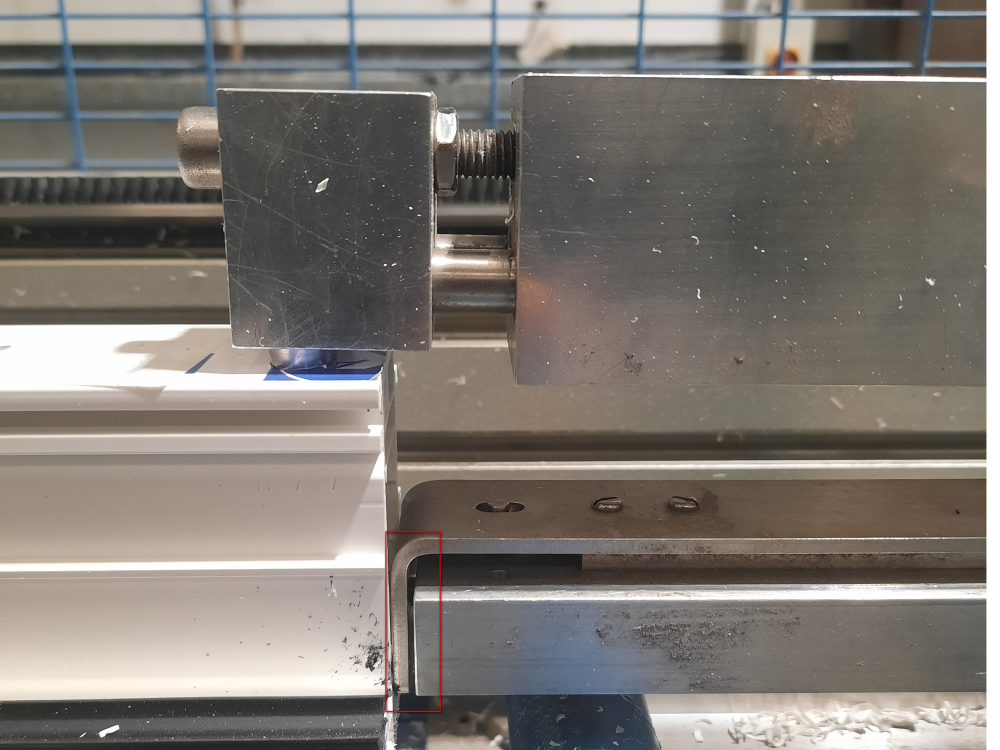
confluence ZX5_Datum_and_Grip_Pin_Setup_GripGap.jpg
27/08/25 Moved to confluence
Click Hereen none 0 Draft
Vous avez entré un nom de page invalide, avec un ou plusieurs caractères suivants :
< > @ ~ : * € £ ` + = / \ | [ ] { } ; ? #
 Français
 English
 Deutsch
 Español
 Italiano
 Português