Setting the laser distance sensor for the forward clamp out input (Vorlaufwagen)

Difficulté
Difficile
Durée
10 minute(s)
Sommaire
- 1 Introduction
- 2 Video d'introduction
- 3 Étape 1 - Ensure this input is Inverted in IODef
- 4 Étape 2 - Move the Clamp assembly to its out position
- 5 Étape 3 - Select Rotary switch Q1
- 6 Étape 4 - Set threshold
- 7 Étape 5 - Select Run Mode
- 8 Étape 6 - Test
- 9 Étape 7 - If you need to reset default settings
- 10 Étape 8 - Error messages
- 11 Commentaires
Introduction
The out sensor used for the vorlaufwagen cannot be a standard reed switch because the cylinder that drives this output is a telescoping version. It is impossible to detect the out position.
Therefore, a sensor is fitted that must be programmed to set a high output when it detects the full range has been reached
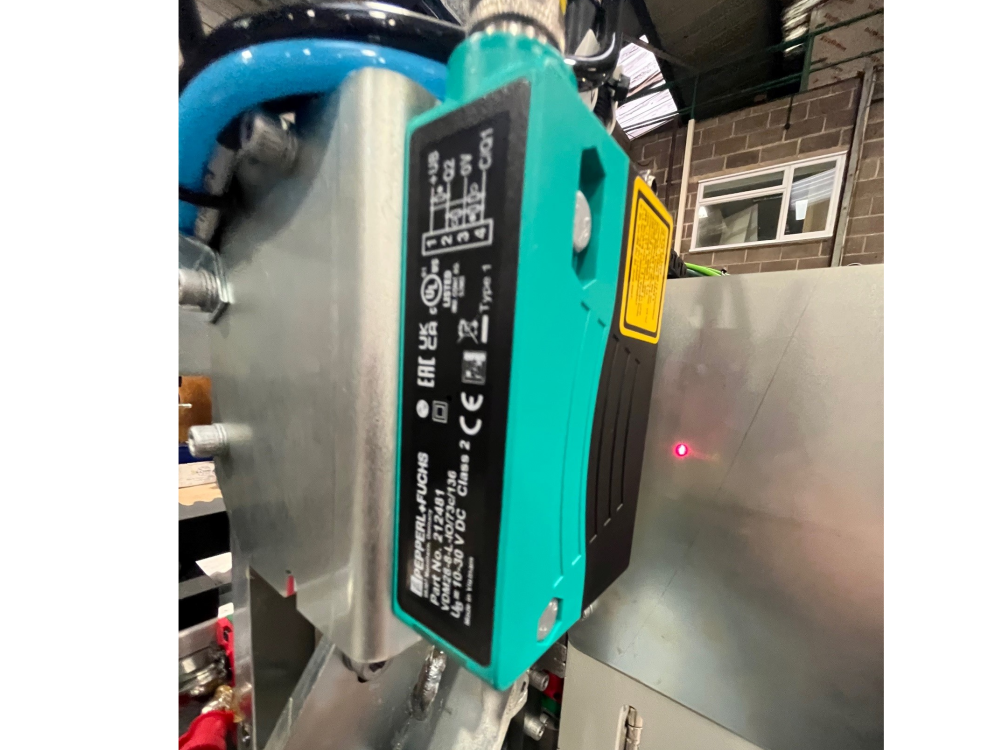
The sensor is a Pepperl+Fuchs VDM28-8-L
Datasheet can be downloaded here
Function
The distance measurement device contains one transmitter and one receiver incorporated into a single housing. The transmitter light is reflected back to the receiver from a target. The sensor determines the distance to the target and triggers a switching function or supplies the relevant measured value for processing.
Assembly instructions
The sensor can be mounted by means of through holes or by using a mounting bracket or mounting clamp
Ensure that the surface is level in order to prevent the housing from becoming distorted when the fittings are tightened. It is advisable to secure the nuts and screws using spring washers in order to prevent the sensor from being incorrectly adjusted.
Connection
Connect the device in accordance with the connection diagram in the datasheet.
Adjustment
The green LED lights up when the operating voltage is switched on.
Adjust the sensor so that the laser point is on the gripper bodyVimeo
Étape 2 - Move the Clamp assembly to its out position
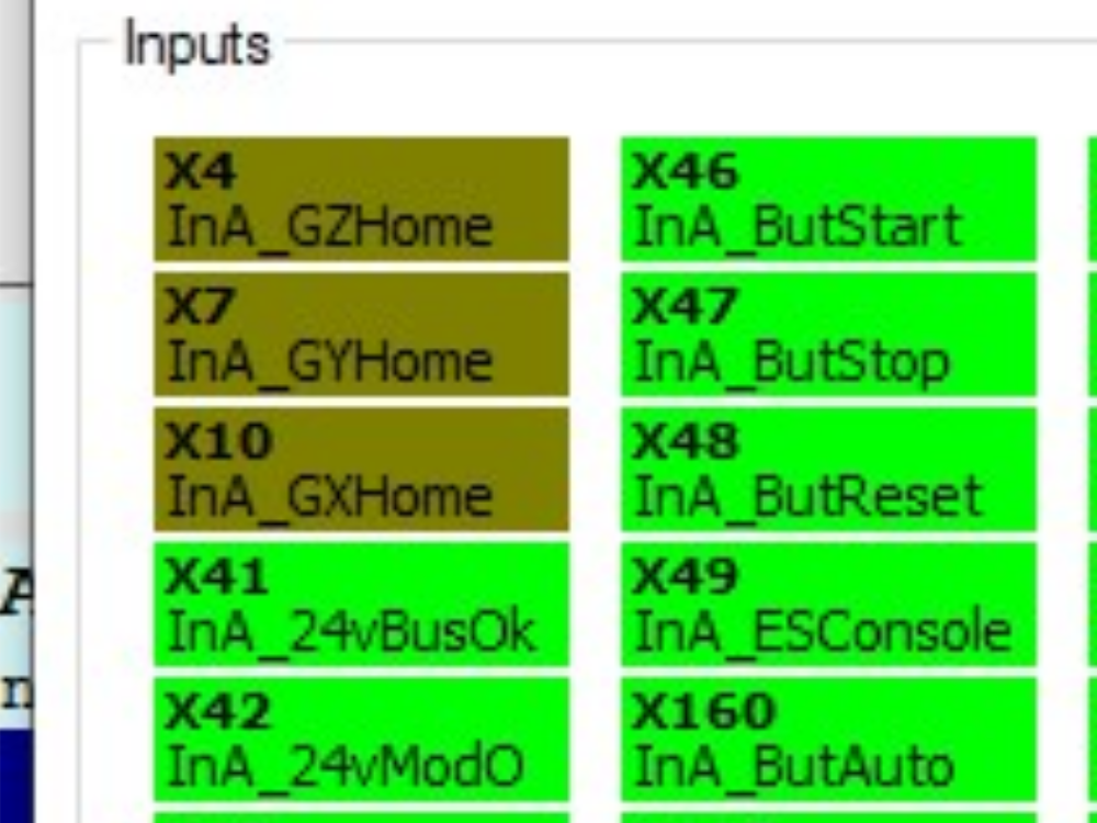
Via IO screen
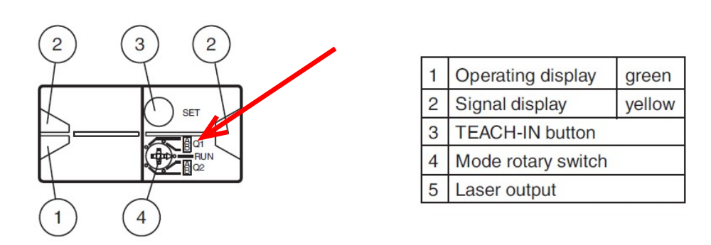
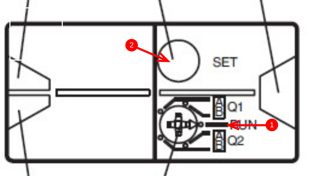
Étape 3 - Select Rotary switch Q1
Select Q1
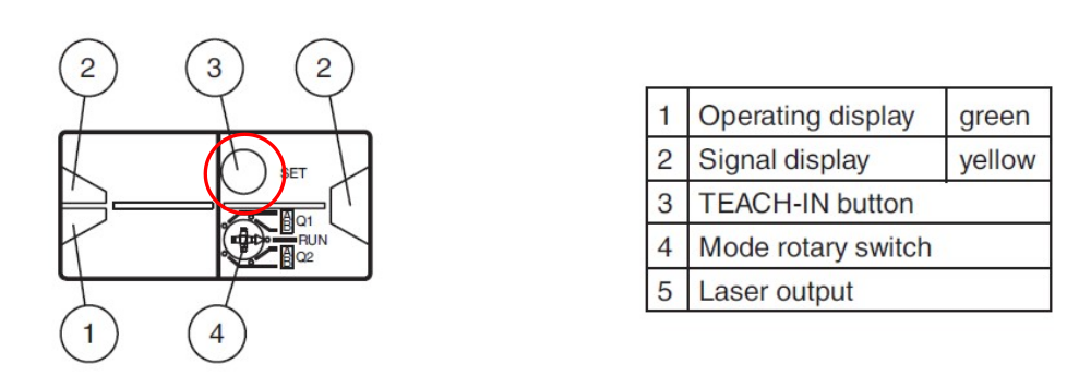
Étape 4 - Set threshold
Temporarily place a length of profile offcut of 70mm thickness in front to the laser dot (you will need another pair of hands to help)
- To store a switching threshold (distance measured value), press and hold the "SET" button until the yellow and green LEDs flash in phase (approx. 2 s).
- Teach-In starts when the "SET" button is released.
- A successful Teach-In is indicated by rapidly alternating flashing (2.5 Hz) of the yellow and green LEDs.
- An unsuccessful Teach-In is indicated by alternating flashing (8 Hz) of the yellow and green LEDs.

Étape 5 - Select Run Mode
Rotary switch (4) to centre

Étape 6 - Test
Étape 7 - If you need to reset default settings
- Set the rotary switch to the "RUN" position
- Press and hold the "SET" button until the yellow and green LEDs stop flashing in phase (approx. 10 s)
- If the green LED lights up, the procedure is complete
Étape 8 - Error messages
• Short circuit: In the event of a short circuit at the sensor output, the green LED flashes with a frequency ofapprox. 4 Hz.
• Teach error: In the event of a teach error, the yellow and green LEDs flash alternately with a frequency of approx. 8 Hz
Draft
 Français
 English
 Deutsch
 Español
 Italiano
 Português