This page is a more in depth explanation of the Bar Data Tab

Sommaire

This tab is split into 3 sections
1. The Bar Queue
2. Bar Drawing
3. Machine Variables
The machine variables should not be adjusted as they are set to describe the type of machine this relates to.
The Bar Drawing shows a rough graphical representation of the operations and cuts on the bar.
Bar Queue
The Bar Queue displays a list of the bars in the batch. This can be expanded by clicking on the + next to the bar to show 4 further options
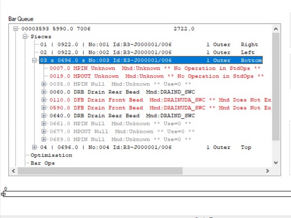
a. Pieces
Expanding this area shows the individual pieces on the bar, this can then be further expanded to show the routing operations on that piece along with the position from the left hand side of the piece, and then further expanded to show the variables relevant to that routing operation (e.g. Slot Length)

b. Optimisation
This area shows the optimisation detail including gaps between the pieces etc.
c. Bar Ops
This area shows the operations and cuts as positions on the bar rather than positions on the piece as shown below.

d. Bar Recipe
The bar recipe shows each action that will be taken on the bar, along with the action number which is shown on error reports. A list of recipe actions is shown below

Please note, at the end of each of these lines may be 2 codes separated by a colon
e.g. KPF110: SL1Z2PT2
This denotes the start of an operation, the code before the colon is the code sent by the office to denote the routing operation, the code after the colon is the program or macro used to determine the tool/axis movements needed to produce the machining operation.
SP Speed Setting
This command sets the speed for an axis or group of axes.
- Format
- SP Axis,Speed,00,0.0,0.0,0.0,0.0
- Speeds
- -1.0 Traverse (fast) speed for all axes
- Axes
- 00 X Axis
- 01 Y Axis
- 02 Z Axis
- e.g
- SP 00,-1.0,00,0.0,0.0,0.0,0.0 Set Traverse Speed for all axes
- SP 01,44,0,00,0.0,0.0,0.0,0.0 Set Y axis Speed to 44
MA Move Absolute
This command moves to an absolute position for the specified axis.
- Format
- MA Axis,Position,00,0.0,0.0,0.0,0.0
- Axes
- 00 X Axis
- 01 Y Axis
- 02 Z Axis
- e.g.
- MA 01,69.0,00,0.0,0.0,0.0,0.0 Move Y Axis to an absolute pos of 69m
MR Move Relative
This command moves to relative distance from the current position.
- Format
- MR Axis,Position,00,0.0,0.0,0.0,0.0
- Axes
- 00 X Axis
- 01 Y Axis
- 02 Z Axis
- e.g.
- MA 01,69.0,00,0.0,0.0,0.0,0.0 Move Y Axis a further 69mm
TL Tool activation
This command sends the closest of a selected tool type to a chosen angle around the bar and activates it.
Format TL Tool,Angle,00,0.0,0.0,0.0,0.0
Tool The tool Ids are determined in the settings area described previously, a sample setting is shown below.

e.g. TL 03,90.0,00,0.0,0.0,0.0,0.0 Send the closest 5mm tool to 90 degrees.
GO Go Command
This command activates the previous commands, which in effect wait in a queue until the go command is activated. This command has no sub variables.
e.g. GO 00,0.0,00,0.0,0.0,0.0,0.0
WI Wait for Idle
This command instructs the machine to wait until the axes are idle i.e. the positions previously specified are reached.
e.g. WI -01,0.0,00,0.0,0.0,0.0,0.0
WA Wait for a specified time
This command tells the machine to wait for an allotted amount of time before the next command is executed.
SC Saw Cut
This command activates a saw cut.
ToolOff Turn Tool Off
Turns the specified tool off.
HL Hole
Performs a Hole operation.
VT Vector Move
Moves 2 axis in conjunction with each other.
OP Output
Checks a specified output signal is made.
LB Label
Prints a Label
WaitOnLoad Wait for load operation
Waits for the bar to load
ToolH Tool Half Plunge
Retracts the Double plunge cylinders (Plunge Half) between slots on a double plunge operation.
To Return to the main page, please click WinMulti Software Operating Guide
Draft
 Français
 English
 Deutsch
 Español
 Italiano
 Português