This module should give the trainee a general understanding of the concepts behind the original "Flowline" and "ZX4" and how the machine is broken down into simple sub-systems. The module is aimed at anyone who wishes to know the machine in more depth than an operator, and is the basis for further modules.

What is a Flowline?
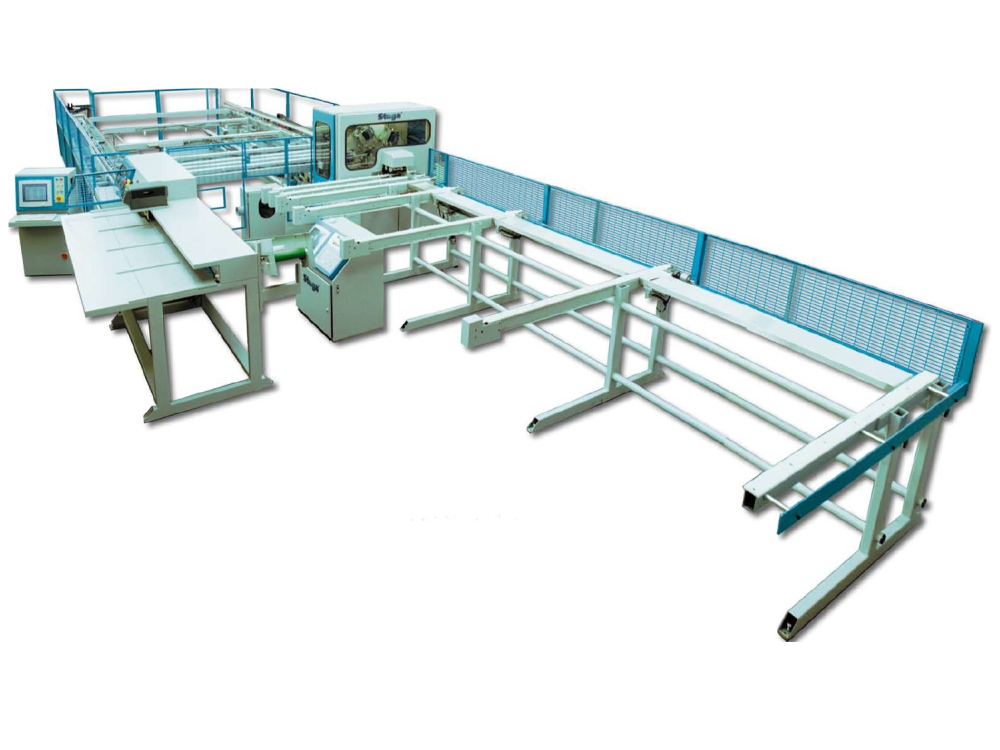
The Flowline is an extremely versatile Sawing and Prepping Centre designed specifically for British window systems. All possible requirements of sawing and prepping required can be carried out on this machine including ninety degree, forty five degree and arrowhead saw cuts, 'V' and 'Y' notches, trickle vents, drainage, espag prep, all door preps and much more.
It designed to cut any combination and number of drainage holes, espag preps and routed slots. A V notch option allows the centre to cut any type and style of V notch. It achieves this by employing any one of up to six different machining heads which can approach the work from any angle 0 to 360 degrees.
Main Parts
The Flowline comprises three modules – machining centre, transfer table and sawing centre. The modules are separate machines in their own right. The sawing and machining modules have their own control panels and displays.
Having separate sawing and machining modules working in tandem preclude delays caused by saw waiting for machine or vice versa. The Transfer Table works as a buffer station, balancing out the ebbs and flows of production
Machining Centre
Product Flow
The extruded bar is loaded onto an infeed table where it is cross-fed to the first set of clamp rollers. The rollers are activated which feeds the work into the machining area. Here it mates with a gripper arm which can move to locate accurately to any section. A switch on the gripper mechanism signals that the work piece is properly loaded and so machining can take place. The drive motor for the rollers is disconnected by a magnetic clutch allowing the profile to move freely either way in the rollers.
Positioning of the machining operation along the profile is carried out by the gripper pulling the workpiece through the rollers. Spindle heads are positioned with 3 axes of movement - up/down, in/out and rotary position. This allows any spindle to get to any position.
When machining is complete, the work is pulled further out and ejected onto the Transfer Table.

Laser Alignment
If the laser alignment option is fitted (standard on ZX3 and ZX4), the last prep in the bar is a 10mm hole through the profile from front to back. This type of hole was chosen because it can be put in any shape of profile.
System Diagram

Axes
There are five axes on the flowline Machining Centre:
| Axis No | Axis Letter | Description |
| 0 | X | Axis along the length of profile. The X axis motor pulls the profile through the machine with the gripper assembly
Positive direction is from machining centre towards outfeed Zero position is spindle centreline Drive is provided through a 5:1 Gearbox and pinion on rack |
| 1 | Y | Axis in and out for tooling ring.
Positive direction is towards rear of machine Zero position is 50mm from backfence rollers, towards the front Drive is provided through a 5mm pitch ballscrew (10mm pitch on ZX4) |
| 2 | Z | Tooling Ring up and down
Positive direction is up Zero position is 50mm from bottom rollers, measured up Drive is provided through a 5mm pitch ballscrew (10mm pitch on ZX4) |
| 3 | R | Tooling Ring rotate 0-360 degrees
Positive direction is anticlockwise as viewed from infeed side Zero position is spindle 1 at 0 degrees Drive is provided by a high inertia motor through a gearbox and pinion drive |
| 4 | G | Gripper jaw left / right to position for different profiles
Positive direction is towards front Zero position is the centre of gripper level with backfence – note this is not possible to do in practice. Drive is provided through a 5mm pitch leadscrew |
The ZX4 has two more axes for the V notch assemblies:
| Axis No | Axis Letter | Description |
| 5 | V | Front V notch. Positive direction is towards rear
Zero position is blade edge at rear backfence Drive is provided through a 10mm pitch ballscrew |
| 6 | W | Front V notch. Positive direction is towards front
Zero position is blade edge at rear backfence Drive is provided through a 10mm pitch ballscrew |
Gripper
The gripper is used to grab hold of the profile and pull it through the machine. It moves from side to side, depending on the profile. The position is set in the Profile Parameters in the Profile and Operations database (flowops.mdb), and is called “Grippos”. The gripper position relates to the distance between the backfence and centreline of the gripper.
Normally, the programmer would line the gripper up with the reinforcing chamber. However, due to mechanical constraints, the gripper cannot move to <24mm from the backfence. This means that some outerframes have to be gripped on the leg of the profile.
Spindles
Flowline-3
The spindles on a Flowline-3 comprise a drive motor and free running pulley, connected with a drive belt. The pulley diameters can be changed to increase the spindle speed from the motor speed of 3,000rpm up to 12,000 rpm.
The V notch function is carried out with this system driving a 45 degree gearbox and then a 150mm saw blade.
All spindles sit away from the machining area and can plunge in towards the centre when required. This has the benefit that the ring can rotate to the next tooling position immediately when the tool is retracted. This is a great timesaver in the operation cycle because the Y and Z axis movements can be minimised.
ZX4 / ZX3
The ZX3 / ZX4 spindles differ in the following ways:
· The spindle footprint is smaller, allowing 8 spindles (ZX4) on the ring, instead of 6.
· The slideways work on a profiled linear bar
· The spindle is an all-in-one unit comprising high frequency motor and collet. This motor runs at 300Hz = 18,000 rpm and has a much better power output of 0.75kW.
· Double plunge
· To prevent failure modes due to wire overload, the spindles are controlled by a central control board on the main panel and a spindle control board in the control triangles. The system prevents the following failures:

o Relay arc-welding. The spindle control boards have contacts that cannot take the arc voltage if they were directly switched on. The central control board will only allow the relay state to change if the Spindle Enable signal (ie the 300Hz power) to the ring is switched off.
o Overloading Cables. The ring power cables are designed to allow a maximum of 2 spindles on together. The Central Control unit will only allow two opposite spindles to be switched on together.
· The ZX4 has a separate area for V notching. This mechanism incorporates 4 assembles for each of the front infeed, front outfeed, rear infeed and rear outfeed blades. The front and rear pairs of blades are on independent axes, named V for the front, W for the rear. The separate heads allow for faster operation and better swarf extraction
Transfer Table
System Diagram

The transfer table control comes from a PLC in the transfer table cabinet. It communicates with the Machining centre in that it tells the software if the first sensor position is free (Ready To Accept)
The communication with the sawing centre is two way, the Transfer Table system waits for a saw Ready To Accept signal, and then tells the saw when a bar has been loaded correctly.
Product Flow

The sensors on each station detect if a bar is there. If a bar exists and the neighboring space is empty then activate the dog. This is repeated for each station. If any dogs are activated, then run the sequence to move the bars along one station.
Sawing Centre

System Diagram
The ACEpc runs a program called saw.exe that runs the operator interface and controls the machine. 16 inputs and 16 outputs are catered for using the ACEpc internal PC104 bus, using a 16 input and 16 output card.
The motion of the pusher axis is controlled via COM1 serial port with a NextMove ESB Motion controller card. This also give 8 extra inputs and 8 extra outputs.
Product Flow

A batch is loaded into the saw across a network connection. The operator presses auto load and start and the next bar is loaded from the transfer table. Each cut piece consists of two cuts – lead and tail. The pusher pushes the profile to the position for the lead cut, the saw head rotates to the correct position. The cut is made. The same process is repeated for the tail cut, but as the piece is cut through, the piece is ejected onto the outfeed table.
Offcuts
The entire process is repeated for each cut piece. The machine deals with the offcut left at the end in 4 separate ways:
1. If the offcut exceeds the outfeed table length, the operator is asked to press start and the siren sounds. This ensures the operator can check that the outfeed area is clear of people and obstructions
2. If the offcut is large enough to be handled onto the outfeed then it is ejected like a cut piece
3. If the offcut is too small to be ejected, but too large to be pushed down the chute, it is cut up into pieces that are small enough to fit down the chute.
4. If the offcut can fit down the chute it is left on the saw table for the next bar to push it out of the way.
Laser Alignment
If the laser alignment upgrade is fitted (standard on ZX4s and ZX3s), the saw measures the laser hole position during the load process. The position of the hole is used to align the sawing positions to the machining positions from the machining centre.
Axes
The sawing centre has one axis called the pusher axis. The axis pushes the profile through the sawing machine to the different saw cut positions using a gearbox and rack and pinion assembly. Its datum position is at the far end of the machine. The zero position for the axis is the saw blade centerline.
Saw Head Rotation
The saw head can rotate to 3 positions - -45 degrees, 0 degrees and 45 degrees. This allows the saw head to cut all the combinations of mitre, square and arrow head cuts required.
When cutting mitre cuts on the profile, the saw blade rotation point is at a fixed position from the backfence. When cutting arrow heads, the saw blade rotation point is centralised to the profile, meaning that the arrow head cut is always in the centre of the profile.
Draft
 Français
 English
 Deutsch
 Español
 Italiano
 Português