Correct setting and adjustment of the Stuertz Conveyor and Indexing System

Quick Adjustment Guide
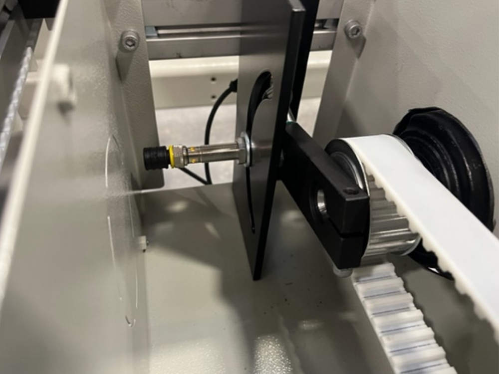
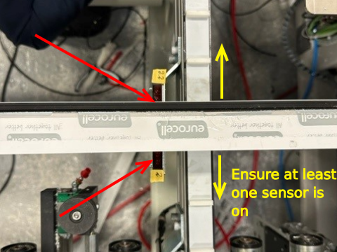
Goal is to get the second upstand just beyond the rear fence rollers
The photo shows a situation where the index is just behind the rollers, so would need to move forwards

To adjust the second upstand stop position, undo the index arm locking bolt and rotate it around the shaft.
| Direction | Photo | Adjustment | |
|---|---|---|---|
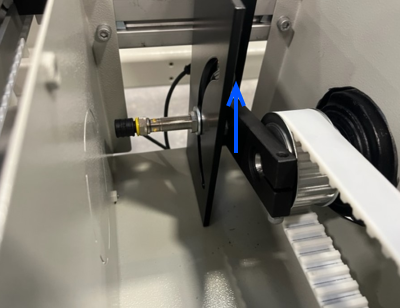
| Towards Operator |  |
 |
|
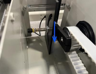
| Away from Operator |  |
 |
General Sequence of Operation
- On a start signal, release motor mechanical brake, start motor
- Wait until INDEX and BRAKE sensors are inactive
- Wait for BRAKE sensor active
- Decelerate motor
- Ensure INDEX sensor is covered
- Apply Mechanical Brake
General Setup Procedure
- Program the inverter to run forwards and backwards at 50Hz, 0.5s acceleration and deceleration
- Use the advance button to move to index one position / index
- Check that the INDEX sensor is covered on deceleration - adjust the INDEX on the arc so that this is the case
- Measure the position of the index to the backfence - this should be 130mm.
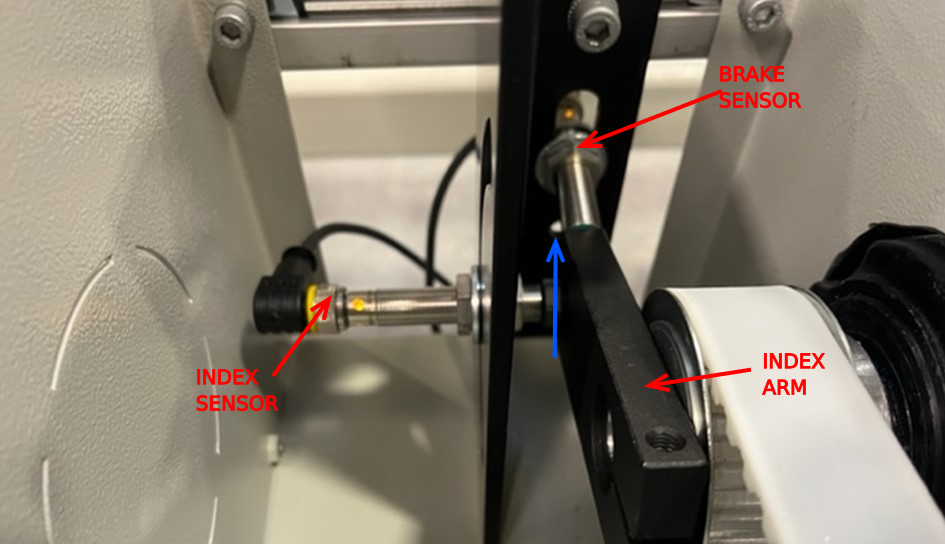
- Adjust the position by loosening the Allen key fastening on the INDEX ARM. Rotate up at the rear to move the index closer to the backfence (Arrow shown in blue). Remember, one revolution is one index pulse length (200mm)
- Check the sensor spacing vs the slimmest outer frame profile - ensure at leas one sensor is on across slot range in both position 7 and 8
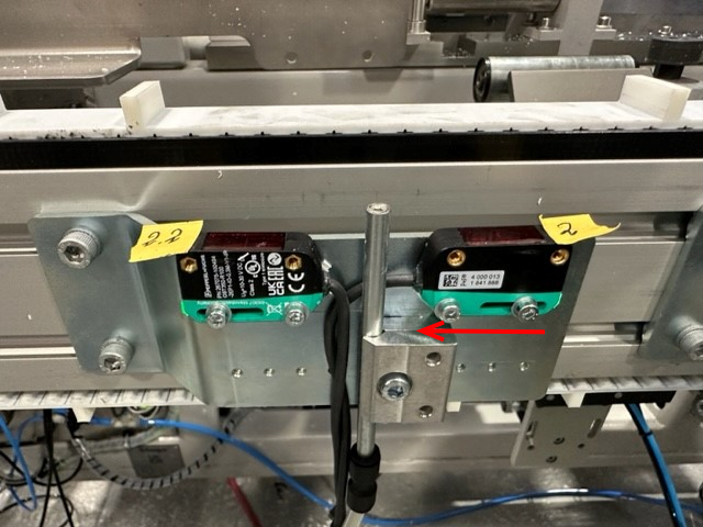
Position of sensors can be adjusted on hole pitch - For 50mm slim outer, the rearmost sensor needs to move forward one pitch
IO on Autoflow Mk4 Infeed Table

| IORef | Reference Code | Function | Notes |
|---|---|---|---|
| Y109 | OuA_IMotFwd | Rotate Forwards | Forwards means belts should take the profile from the operator towards the backfence |
| Y110 | OuA_IMotRev | Rotate Reverse | Belts rotated in reverse |
| Y382 | OuA_IMotBrake | Motor Brake | Motors have a brake function white needs to be ACTIVE / ON to release the brake |
| X388 | InA_CnvBrk | Sensor to trigger deceleration | This sensor tells the motor when to decelerate to stop the profile close to the loading position. |
| X033 | InA_Index | Sensor to identify that conveyor is in position |
Draft
 Français
 English
 Deutsch
 Español
 Italiano
 Português