Root cause analysis of drainage tool breakage at the start of a bar


Problem
Seemingly random tool breakage on 5mm router bits. Always at the start of a bar, but only on outer frame.
The video of the drain slot operation shows the spindle plunge, then the x axis move before the spindle switches on. This is incorrect - the spindle should switch on before the movement happens.
There are no inverter errors associated with this problem. The machine carries on as if nothing has happened
Analysis
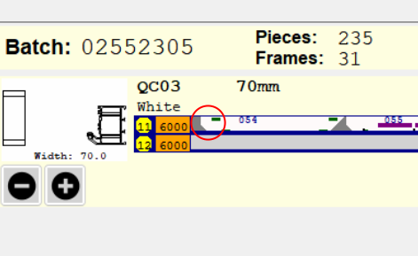
Using the ring camera video playback in slow motion clearly showed the error in the sequencing of the motor / plunge.
It was proved to be 100% repeatable for and operation at the start of the bar on outer frame.
Used the Yaskawa Trace recorder to track the inverter power output and status
Running the spindle on the IO screen shows no issues at all - the cycle can accelerate and decelerate all day long with no inverter errors.

Running the trace during the repeatable break situation showed an anomaly (below). This trace was repeatable each time the operation at the start of the bar was run

The first trace (1) is the result from the datum holes - the red peaks show the current peaks when accelerating then decelerating.
The second trace shows the fault where the red trace shows the current dropping. The blue line shows that the inverter has not created this dip.
Because the red trace is a measure of output current, the dip must be reflecting a physical interruption in the current passing to the motor. The blue trace proves that it is not the software "RunFwd" output or the inverter doing this, therefore it has to be an external connection or relay problem.
All electrical connections were checked
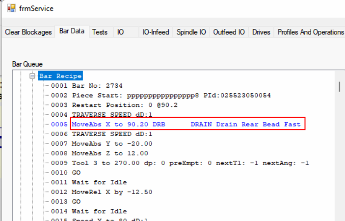
To see if this is a mechanical location issue, Set up the X, Y, Z, R axes on the machine to the actual axis positions during this operation. These positions are taken from the bar recipe
| Axis | Position | Notes |
|---|---|---|
| X | 90.2-12.5=77.8 | Position of operation minus the startOffset for a drainage slot |
| Y | -20 | |
| Z | 12 | |
| R | 315 | Spindle 8 at 270 degrees |
Attempting to run the spindle in these axis positions uncovered the root cause - the spindle relay output (SPIN8) was not able to switch on.
Solution
The solution lies in a set of parameters called "xHolds". These parameters are there to prevent an output from switching on and clashing with the gripper if the x axis is in a certain location. On this machine setup, the xhold for SPIN8 was set to 80. When the operation occurs, the x axis position is 77.8, therefore the SPIN8 output is held off until the x axis moves to a position >80mm
The use of SPINx in xholds is actually incorrect. The correct output to prevent clashing with the x axis gripper on a ZX5 is SPPLx (Spindle Plunge). SPINx refers to the control relay.
| Before | After |
|---|---|
 |
 |
Further Analysis
It should be noted that under "normal" conditions. the drainage slot would fall in the "minable" zone. (See Minable and Maxable - Operations at the ends of the bar). This would add a minable gap at the start. However, this case is overridden by the Y notch at the start of the bar which has a start bar gap of zero. This is a bug in the system when we have this specific set of circumstances.
Draft
 Français
 English
 Deutsch
 Español
 Italiano
 Português