Instructions to align slider units and mesh racks

Difficulté
Difficile
Durée
6 heure(s)
Sommaire
- 1 Introduction
- 2 Étape 1 - Drive pinion mesh setting
- 3 Étape 2 - Check for clearance
- 4 Étape 3 - Set mesh
- 5 Étape 4 - Repeat
- 6 Étape 5 - Alignment
- 7 Étape 6 - Set First and last position
- 8 Étape 7 - Please note
- 9 Étape 8 - Set Wire line
- 10 Étape 9 - Adjust Remaining slide units
- 11 Étape 10 - All pin positions must be checked
- 12 Étape 11 - CAUTION!!!
- 13 Étape 12 - Quality check
- 14 Étape 13 - Fit rack stop one D0015626
- 15 Étape 14 - Fit rack stop 2 D0015626-OH
- 16 Commentaires
Introduction
Tools Required
Standard hex key set
Stubby hex key set
Wire line
Quick clamps
P0000501 non return valve x 3
Standard HSS drill set
Standard tap set
Tape measure
300mm rule
Parts Required
D0015625 x 1
D0015625-OH x 1
E0000336L x 2Étape 1 - Drive pinion mesh setting
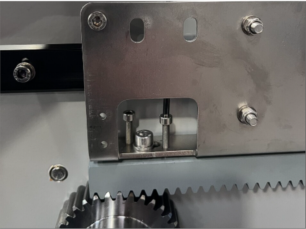
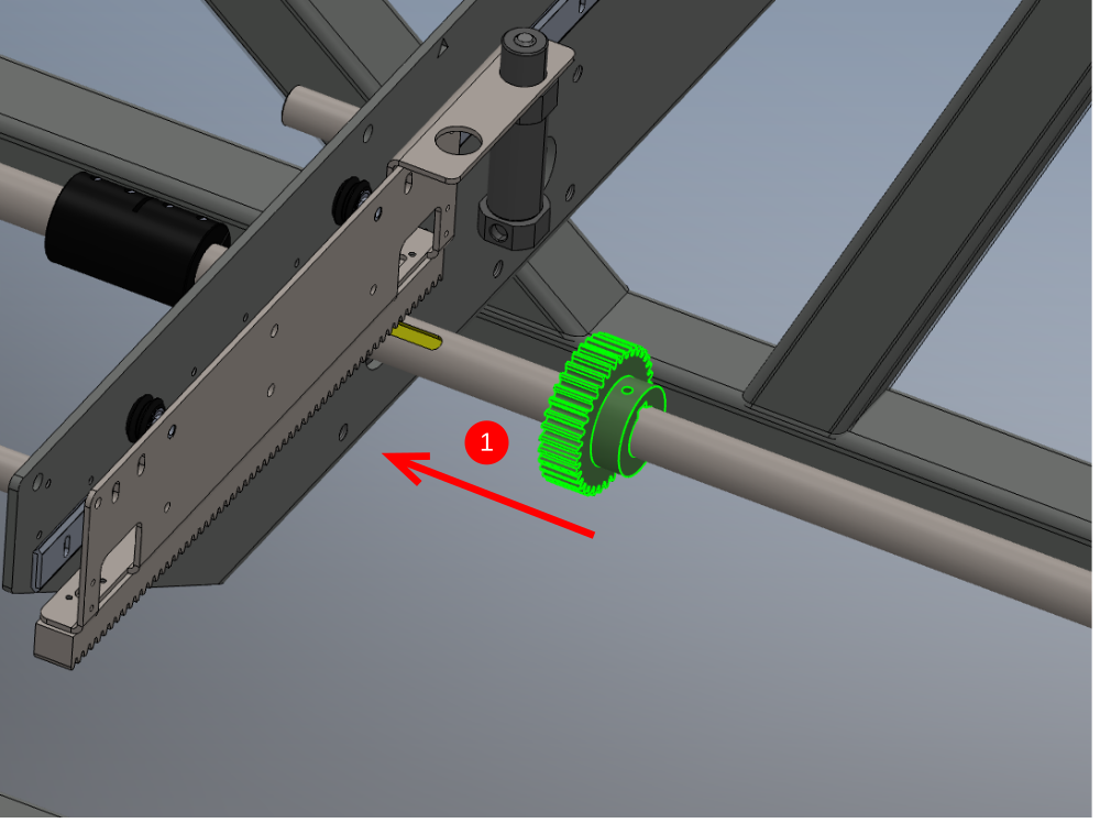
Mesh requires setting between slider unit and drive pinion
1 It is vital that the correct drive meshing is achieved.
2 Once set, there should be between 0.5 and 1mm movement in the direction shown, which will indicate the correct tooth meshing has been obtained.
3 This need to be checked at all points of travel as shown


Étape 2 - Check for clearance
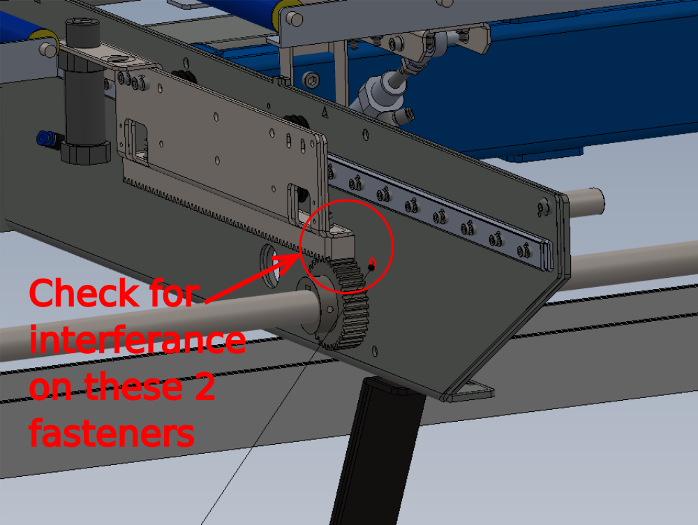
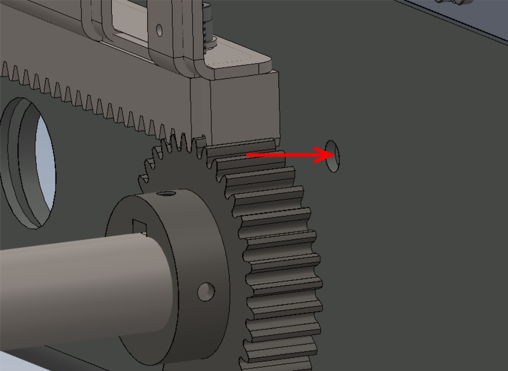
Clearance check must be completed at this stage
Interference may be possible from bearing block fasteners indicated against drive rail
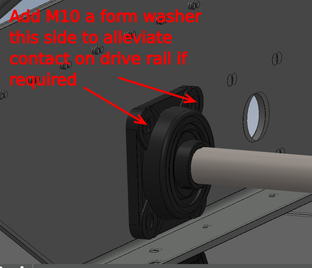
Space M10 cap heads with M10 washer is drive rail contacts fastener end
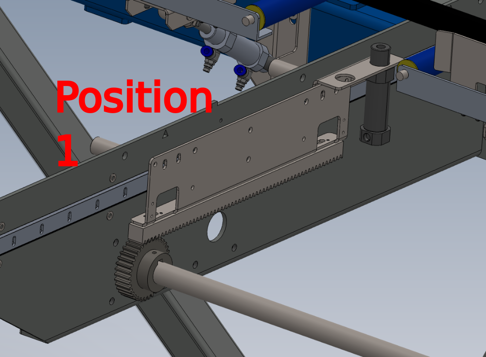
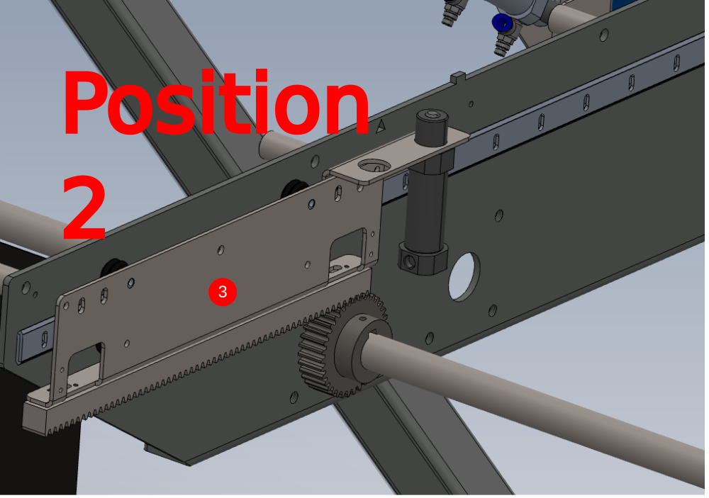
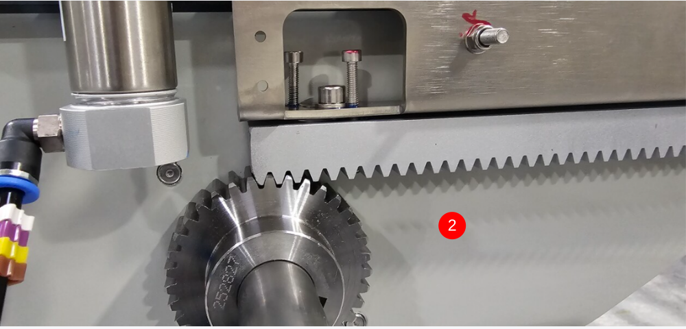
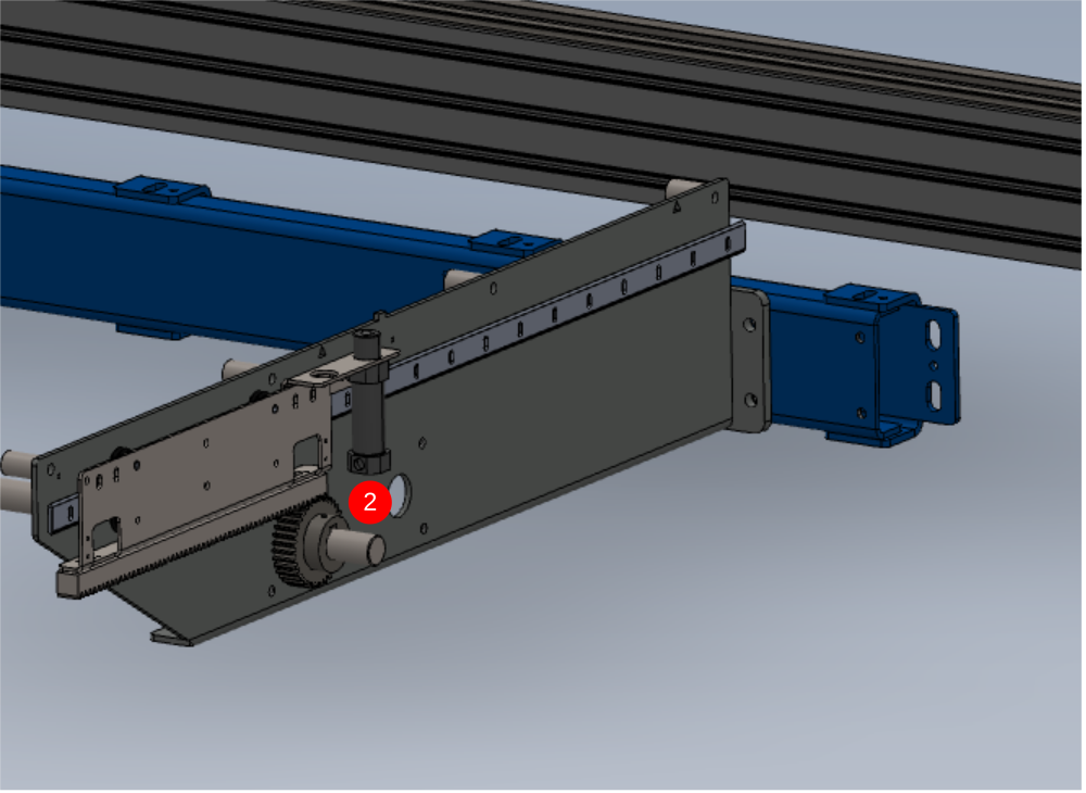
Étape 3 - Set mesh
1 Slide drive pinion into position 1 under drive rack
2 Use M4 adjuster screws to adjust height of rack and M6 to secure
3 Slide out drive pinion and move rack to position 2. Refit drive pinion
4 Use M4 adjuster screws to adjust height of rack and M6 to secure
5 Repeat steps until correct meshing is present at all points indicated to check
Do Not glue any of the M4 /M6 socket caps used for adjustment as this will be done at a later stage

Étape 4 - Repeat
Repeat step two for remaining 8 slider units

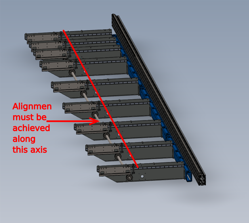
Étape 5 - Alignment
Alignment of cylinder pins is vital, and the following should be maintained
1 Alignment should be parallel to main hepco beam
2 Alignment should be Straight
To achieve this the following steps are required
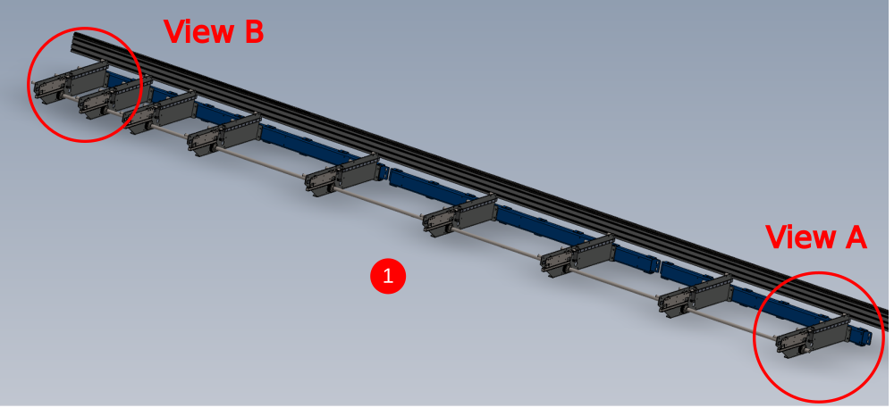
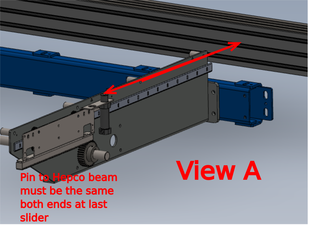
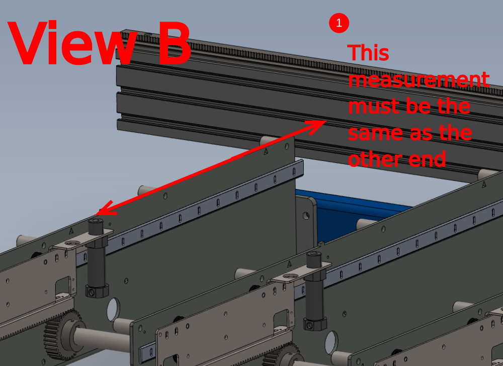
Étape 6 - Set First and last position
1 Set First and last slider into the position shown to align indicated hole with fixing point on support arm. Slide pinion into position once slider has been moved to correct point.
2 Fine adjustment can be gained by Removing tension off M6 bolt on drive rail , and using slot to change position of drive rail mounting . Use Socket cap bolt to lock position onto support arm
3 Check measurement between pin and hepco beam on both sliders to ensure they are the same Tolerance -+ 0.5mm


Étape 7 - Please note
Cylinders do not require to be piped up to complete this step .
Non return valves are stated in the following steps to be used, thus negating the requirement to run pipe looms or pipe work jig can be used
Étape 8 - Set Wire line
Use dokit Alignment guide using wire line to ensure alignment is completed correctly
1 Attach P0000501 non return valve with 6mm pipe to first and last cylinder and purge with air to maintain active position of cylinder.
2 Set wire line between these two active cylinders


Étape 9 - Adjust Remaining slide units
Remaining slide units now need adjusting to align to the wire line .
Adjust one at a time, and use a P0000501 non return valve and 6mm pipe to purge each cylinder as you work on it.
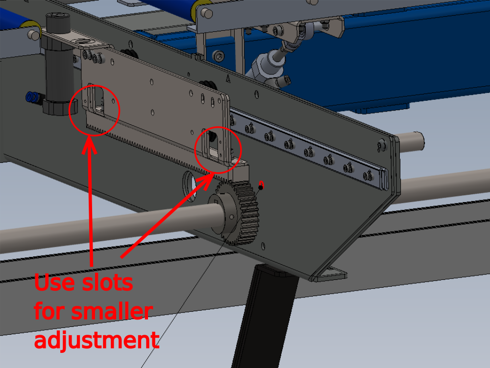
Use movement in slots indicated to adjust smaller increments once drive rail has been positioned
Once a cylinder is set, remove non return valve and place on next cylinder being set

Étape 10 - All pin positions must be checked
All pin positions must be checked with a steel rule measured squarely to the hepco rail
All measurements must be to a tolerance of -+0.5mm

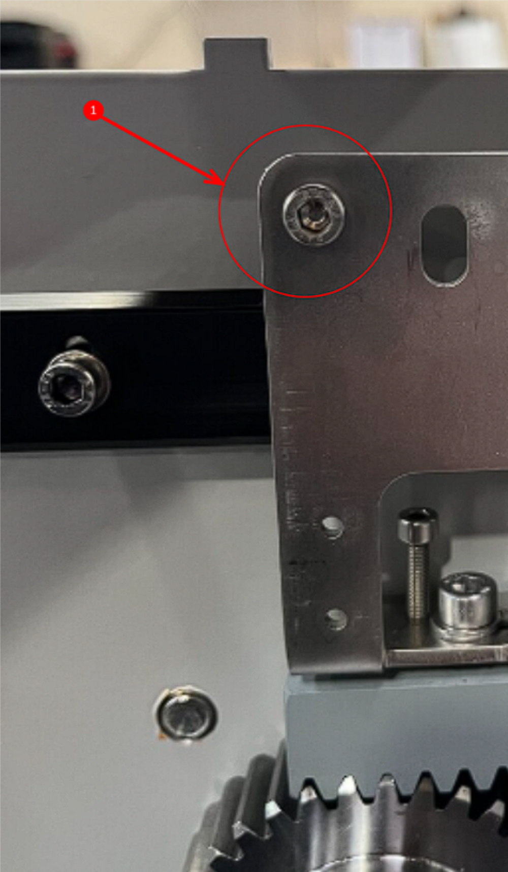
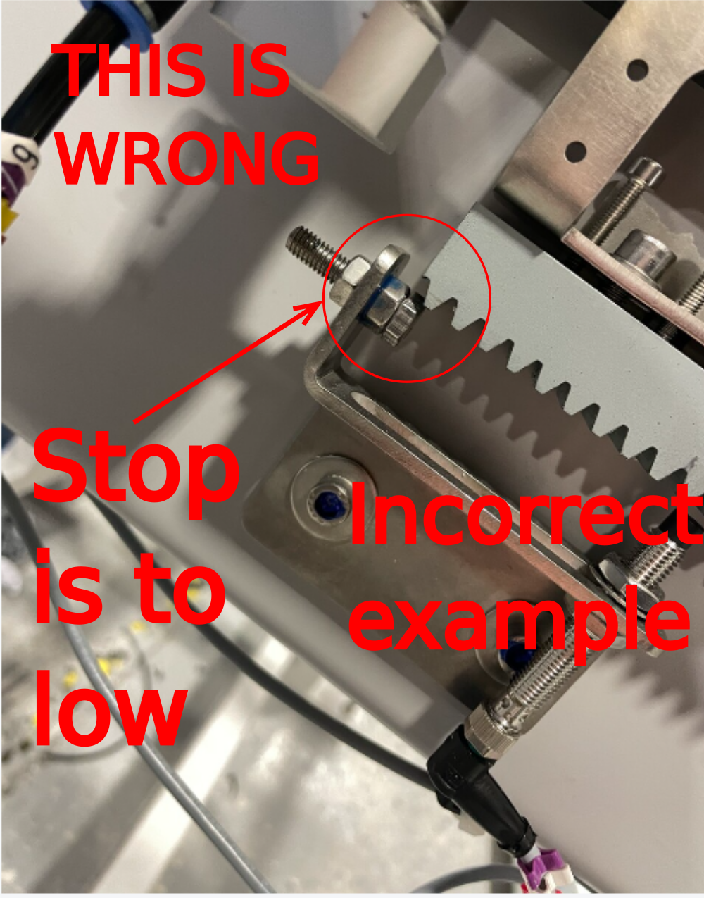
Étape 11 - CAUTION!!!

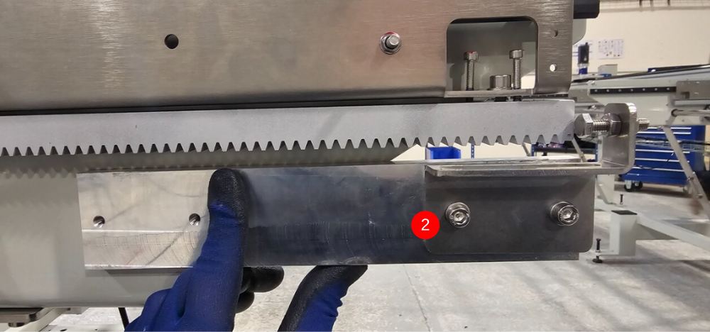
Étape 12 - Quality check
Attached picture is of a rack stop fitted INCORRECTLY
Stop bolt must contact drive rail correctly as shown in next step
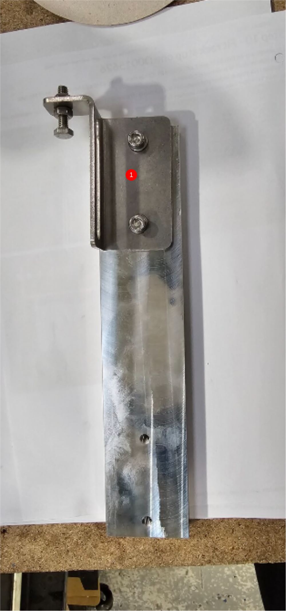
Étape 13 - Fit rack stop one D0015626
1 Assemble one off D015625 and 1 off D0015625 -OH as shown using a M6 x 25 hex set bolt and 2 M6 nuts.
2 Rotate drive shaft to position rack as show
3 Position rack stop as shown and mark, drill and tap to M6 . Ensure M6 hex set bolt is set as shown for maximum adjustment
Use M6 x 16 socket caps and A form washers to fix


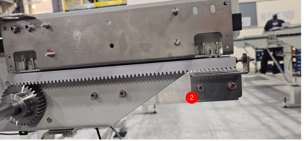
Étape 14 - Fit rack stop 2 D0015626-OH
D00015629 Rack extension
1 Assemble rack extension and hard stop bracket as shown using 2 off M6 x 16 socket caps and 2 off M6 A form washers . Fit hard stop bolt 1 off M6 x 25 set bolt and M6 Standard nut as shown 2 Fit assembly to arm number ( clarify which arm this is fitted to please)
Drill and fix with M6 x 16 socket caps and A form washers

Draft
 Français
 English
 Deutsch
 Español
 Italiano
 Português