This page contains all of the different electrical safety devices used on the Stuga machines and how they are wired. Fore the safety circuit master document, use this link: https://stuga.dokit.app/wiki/Fault_Finding_-_Safety_Circuits_Master
Sommaire
| Component Name | Component Picture | Part Numbers | Wiring Details |
|---|---|---|---|
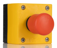
| Emergency Stop Button Module
(Eaton) |
Button Module - E0001072
|
This emergency stop button comes complete with an enclosure and emergency stop button. Normally open (NO) and normally closed (NC) contacts are connected to the box which the button acts upon when pressed/ released. The is a push to activate and pull to deactivate button.
This emergency stop button will typically be found with 2 NC contacts and 1NO contact. The 2NC contacts are for the safety circuit loop wiring and the 1NO contact is for the feedback to the PLC. How the button is wired is machine dependant. | |
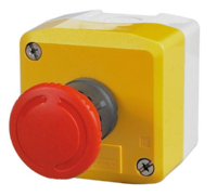
| Emergency Stop Button Module
(Telemecanique) |
Button Module - E0000452
|
This emergency stop button comes complete with an enclosure and emergency stop button. Normally open (NO) and normally closed (NC) contacts are connected to the box which the button acts upon when pressed/ released. The is a push to activate and twist to deactivate button.
This emergency stop button will typically be found with 2 NC contacts and 1NO contact. The 2NC contacts are for the safety circuit loop wiring and the 1NO contact is for the feedback to the PLC. How the button is wired is machine dependant. | |
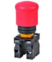
| Emergency Stop Button Panel Mount (Eaton) | Button Module - E0000078
|
This emergency stop button is a panel mount button that comes with a contact carrier. Normally open (NO) and normally closed (NC) contacts are connected to the carrier which the button acts upon when pressed/ released. The is a push to activate and pull to deactivate button.
This emergency stop button will typically be found with 2 NC contacts and 1NO contact. The 2NC contacts are for the safety circuit loop wiring and the 1NO contact is for the feedback to the PLC. How the button is wired is machine dependant. | |
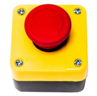
| Emergency Stop Button Module (Schneider) | Button Module - E0000062
|
This emergency stop button comes complete with an enclosure and emergency stop button. Normally open (NO) and normally closed (NC) contacts are connected to the box which the button acts upon when pressed/ released. The is a push to activate and twist to deactivate button.
This emergency stop button will typically be found with 2 NC contacts and 1NO contact. The 2NC contacts are for the safety circuit loop wiring and the 1NO contact is for the feedback to the PLC. How the button is wired is machine dependant. | |
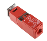
| Interlock Guardswitch (Bernstein) | Guardswitch Unit - E0001568
|
Wired with 2 N/C contacts (out of 3), 1N/O contact and 1 solenoid (Door Unlock). The 2 N/C contacts are split into 2 categories, you have the N/C contact that monitors the state of the solenoid, the N/C contact that monitors the state of the key actuation and a N/C contact that monitors both in series. The N/O contact monitors the state of the key actuation. The solenoid wiring is for unlocking and locking the guardswitch. When no voltage is present on the solenoid wires, the guardswitch will be locked and when voltage is applied, the guardswitch will be unlocked. This is know as a 'power to unlock' guardswitch and this is the type we use on the Stuga machines. | |
| Guardswitch (Guard Master) | Guardswitch Unit (2NC+1NO) - E0001535
|
Wired with 2 N/C and 1 N/O contact. The estop loops use the N/C contacts and the feedback (input to PLC) uses the N/O contact. | |
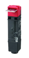
| Interlock Guardswitch (Omron) | Guardswitch Unit (Type B) - E0001054
|
Wired with 2 N/C contacts (out of 3), 1N/O contact and 1 solenoid (Door Unlock). The 2 N/C contacts are split into 2 categories, you have the N/C contact that monitors the state of the solenoid, the N/C contact that monitors the state of the key actuation and a N/C contact that monitors both in series. The N/O contact monitors the state of the key actuation. The solenoid wiring is for unlocking and locking the guardswitch. When no voltage is present on the solenoid wires, the guardswitch will be locked and when voltage is applied, the guardswitch will be unlocked. This is know as a 'power to unlock' guardswitch and this is the type we use on the Stuga machines. | |
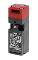
| Guardswitch (Omron) | Guardswitch Unit - E0000087
|
Wired with 2 N/C and 1 N/O contact. The estop loops use the N/C contacts and the feedback (input to PLC) uses the N/O contact. | |
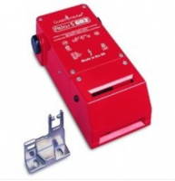
| Interlock Guardswitch (Guard Master) | Guardswitch Unit (w/Key) - E0000061 | This unit is a power to unlock interlock switch. Inside the unit is a terminal rail for all wiring connctions. The unit has 2NC contacts that both monitor the state of the key and the state of the solenoid. The unit has 2NO contacts, 1 that monitors the state of the key only and the other monitors the state of the solenoid only. | |
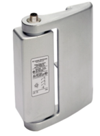
| Hinge Safety Switch (Leuze) | Safety Hinge - E0001176
|
Wired with 2 N/C and 1 N/O contact via an m12 8pin cable. The estop loops use the N/C contacts and the feedback (input to PLC) uses the N/O contact. | |
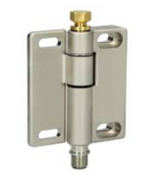
| Hinge Safety Switch (Bernstein) | Safety Hinge - E0000313
|
This hinge switch is wired with an m12 4pin cable. Inside the hinge is a change-over contact (CO) which can either be normally open or normally closed. The brown wire of the cable is common to both normally open and normally closed. The black wire is the normally closed connection (active when hinge is inactive/ door closed) and the blue wire is the normally open connection (active when hinge is active/ door open). The other wire is for a grounding. As this switch only has 1 CO contact, it can only have a single safety circuit loop going through it. | |
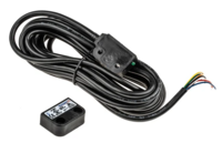
| Magnetic Safety Switch (Omron) | Non-contact Magentic Switch - E0001562 | Wired with 2 N/C and 1 N/O contact. The estop loops use the N/C contacts and the feedback (input to PLC) uses the N/O contact. |
Below is a list of other devices fitted on the Stuga machines which are considered safety related but are not necessarily related or impact the main safety circuit.
010-n- Light curtain - The light curtains are wired with 2 OSSD outputs (Output Signal Switching Device). These are outputs from the light curtain that interact with a designated relay which then controls 2 switches which are wired into the safety circuit. The light curtain is considered part of the safety circuit but it is actually the relay that the light curtain controls which does the safety circuit switching!
011-n- Zero Speed Detector - This is a device that is used to monitor the status of a 3 phase motor. The zero speed detector is not wired into the safety circuit. However, the zero speed detector does stop the interlock guardswitches from unlocking if it does not detect zero speed. It can sometimes be diagnosed that a guardswitch has failed when actually the issue is with the zero speed detector!
012-n- Safety Timer - On some models of the ZX5 you will find a yellow safety timer fitted in the machining centre cabinet. This timer is not wired into the safety circuit but it is controlled by it! This timer allows us a safe amount of time before actuating something. In the case of the machining centre, the timer is used to monitor the safety circuit and when it detects the safety circuit is inactive (emergency stopped pressed for example), it triggers a set time to not allow the door unlock signal to activate. This does 2 things, firstly it only allows the doors to open when the machine is safe and also it allows us to set a time to make sure the machine has come to a complete stop before allowing the doors to open.
Draft


 Français
 English
 Deutsch
 Español
 Italiano
 Português