This tutorial will guide the user through changing the d-sub support stands on a SMC valve bank.

Difficulté
Moyen
Durée
10 minute(s)
Sommaire
- 1 Introduction
- 2 Étape 1 - Valve Bank Types
- 3 Étape 2 - Tools Required
- 4 Étape 3 - Remove 2 Valves
- 5 Étape 4 - Remove the D-Sub Housing
- 6 Étape 5 - Changing the D-Sub Upstands
- 7 Étape 6 - Reassembly
- 8 Étape 7 - STEURTZ TYPE
- 9 Étape 8 - Tools Required
- 10 Étape 9 - Identify Valve Bank
- 11 Étape 10 - Take Apart the Valve Bank
- 12 Étape 11 - Assemble Valve Bank
- 13 Commentaires
Introduction
The SMC valve banks that have a built on d-sub connector (P0001209 and P0001210) are supplied with m2.6 threaded upstands with an m3 stud as standard. The d-sub cables and d-sub etherCAT boxes that we use are UNC4-40 threads and are not compatible with the SMC valve bank. UNC4-40 upstands with an m3 stud (F0000625) have been sourced and are required to be used to make the SMC valve bank compatible with the other d-sub components that are used.
Étape 1 - Valve Bank Types
There are 2 types of valve bank that require this change. The 'Stuga' type and the 'Steurtz' type. The Stuga type is covered between steps 2 and 6 and the Steurtz type is covered from 6 onwards.
Picture 1 is the 'Stuga' type.
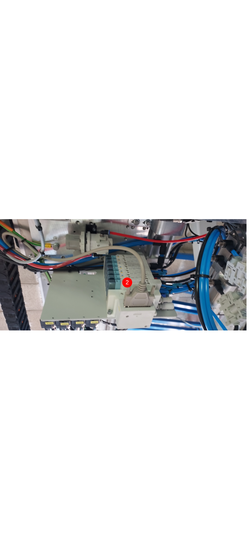
Picture 2 is the 'Steurtz' type (found on Autoflow Mk4 Infeed Tables)

Étape 2 - Tools Required
- Screwdriver set
- Long nose pliers
- Permanent marker
- F0000625 x2 (UNC4-40 Upstands with m3 Stud).
Étape 3 - Remove 2 Valves
Remove the 2 valves closest to the d-sub connector. Make sure to keep the gasket and screws for the valves safe as these will be needed to reinstall the valves later.


Étape 4 - Remove the D-Sub Housing
Remove the plastic housing that incases the d-sub connector. Picture 1 shows the small screws that need to be removed to allow the plastic insert to be removed. Pictures 2 and 3 show the tabs that need to be pressed in to allow the plastic insert to be removed. Picture 4 shows the plastic insert pulling out, which then allows the d-sub connector to be pulled away from the housing (picture 5). Picture 5 also reveals the screws that need to be undone to allow the plastic housing case to be removed. Finally, picture 6 shows the housing case removed and the d-sub inserts are now ready to be changed.


Étape 5 - Changing the D-Sub Upstands
The d-sub upstands are now accessible. The m3 nut that sits on the inside of the d-sub casing fits into a mould so it does not spin when the upstand is removed (picture 1). Using long nose pliers, loosen one of the upstands until it is fully removed (picture 2). The upstand will be replaced but the nut will be used again with the F0000625 upstand (picture 3). If the m3 nut came out, reseat it in the mould and screw one of the F0000625 upstands into it. Tighten the upstand into the nut with the long nose pliers and then mark the upstand with the permanent marker to show it has been changed (picture 4). The same process can then be done for the other upstand.


Étape 6 - Reassembly
The parts are reassembled in the opposite fashion to how they were removed. Start with the housing casing. When placing the housing case into position, ensure none of the d-sub wires are snagged (picture 1). Use the same screws that were removed earlier and make sure they are tightened down and marked with the permanent marker (picture 2). The d-sub connector can then slide into the housing ensuring orientation is the same as in picture 3. The plastic insert can then clip back into place. Again, ensure no wires are snagged (picture 3). The 2 small screws to fix the insert can then be fitted and marked with the permanent marker (picture 4). Finally, fit the 2 valves that were removed earlier (picture 5) and ensure the gasket is fitted.
Jobs a goodun :)


Étape 7 - STEURTZ TYPE
THE BELOW STEPS WILL COVER THE STEPS TO TAKE ON THE VALVE BANKS FITTED ON THE STEURTZ INFEED TABLE
Étape 8 - Tools Required
- PH1 Screwdriver
- Needle nose pliers
- Marker pen
- F0000625 x2 (UNC4-40 Upstands with m3 Stud).
Étape 9 - Identify Valve Bank
Locate valve bank VB02A on the gripper carriage as per the picture. There is another valve bank on the rear service panel.

Étape 10 - Take Apart the Valve Bank
- Remove the Sub-D plug
- Remove the 2 off PH1 screws as pictured.
- Gently remove the white end module from the valve bank - there is a connection behind that you need to disconnect; it is a press fit connection.. Gently pulling and wiggling the white block towards you should remove it.
- Once you have removed the white block, turn it over to expose the 4 off PH1 screws.
- Remove the 4 off screws and put to one side as you will need these later.
- Remove the white cover by lifting it up to expose the upstands and internal wiring. This will expose the area that houses the screws that you need to replace. There is a nut inside the casing for each screw, you can re - use the same nuts for the new upstands.
- Using needle nose pliers, unscrew the 2 off old upstands.


Étape 11 - Assemble Valve Bank
- Replace the 2 upstands with the new ones with the different threads. Mark the 2 off new upstands with a black marker to show that these have been changed.
- Once you have replaced the upstands, fit the cover back on whilst ensuring that you have not trapped any wires. Re - fit the 4 off PH1 screws back into the cover to secure it in place again.
- Align the rear plug and socket arrangement and gently press into place.
- Re - fit the 2 off PH1 screws to secure the white block back onto the valve bank.
- Re - fit the Sub-D connection and secure in place.
Arbeit gut gemacht


Draft
 Français
 English
 Deutsch
 Español
 Italiano
 Português