Setting V notch blade offsets on Ecoline winMulti Software
Sommaire
- 1 Introduction
- 2 Tutoriels prérequis
- 3 Étape 1 - Ensure the Datum and mitreOffset setup has been run
- 4 Étape 2 - Prepare Profiles
- 5 Étape 3 - Measure the bar width
- 6 Étape 4 - Separate the V notch to help measure
- 7 Étape 5 - Cut a V notch of around at a position of around 400mm
- 8 Étape 6 - Measure and Adjust the Depths
- 9 Étape 7 - Measure and Adjust the Separation
- 10 Étape 8 - Set V notch Depth
- 11 Étape 9 - Repeat the depth settings for the rear
- 12 Étape 10 - Check and adjust alignment of V notches to datum holes
- 13 Étape 11 - Back to back check
- 14 Commentaires
Introduction
This is the full setup procedure for V notches on an Ecoline. This should only be needed on initial commissioning or if the shape of the notch has changed due to some physical intervention, for example -
- Blade Change
- Blade buckled
- Tutoriels prérequis
Tutoriels prérequis
Étape 2 - Prepare Profiles
You will need several lengths of large outer frame, around 1m long with square end preps.
Étape 3 - Measure the bar width
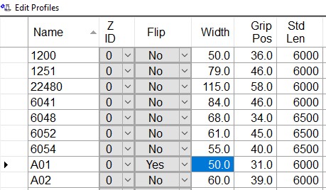
Measure the bar width accurately with callipersSet the width of the sample profile in the flowops program to the nearest 0.1mm
Étape 4 - Separate the V notch to help measure
Starting with Front V notches (repeat this process later for rear V notches)
The distance between the V notch blades is known as the separation. This should be temporarily 'expanded' during testing to make the shapes easier to measure.
It is normally around 136-138, so add 10mm on to the existing parameter to make 146-148
Étape 5 - Cut a V notch of around at a position of around 400mm
Use something around 30-40mm depth
Étape 6 - Measure and Adjust the Depths
The goal is to get both physical blade depths the same by tweaking the depth of the "outfeed" offset using the dOffsetVO.
The notches are named "infeed" and "outfeed" to standardise the notch cut on both left and right feed machines
VI - Front Infeed
VO - Front Outfeed
WI - Rear Infeed
WO - Rear Outfeed
Make the adjustment and run again to check
Étape 7 - Measure and Adjust the Separation
The goal is to reduce the separation back to a good overlap.
The simple way to do this is to measure the 'expanded' separation distance and subtract this from the VSEPERATION parameter
Make the adjustment and run again to check
Étape 8 - Set V notch Depth
Now that the shape of the V notch is correct, adjust the overall depth.
IF this is the "first time "setup on the front V notches, the V axis datum should be changed to ensure the machine is set in the correct base position.
IF you are tweaking the values, use VSTARTPOS and WSTARTPOS adjustments:
Front V Notch
Use the VSTARTPOS parameter
Increasing the VSTARTPOS parameter will make the front notch shallower
Rear V Notch
Use the WSTARTPOS parameter
Increasing the WSTARTPOS parameter will make the rear notch deeper
Make the adjustment and run again to check
Étape 9 - Repeat the depth settings for the rear
Repeat from step 4 for the rear notches
Étape 10 - Check and adjust alignment of V notches to datum holes
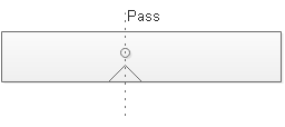
Run a piece with a datum test and V notch in same position
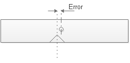
The goal is to align the hole centreline and notch centreline precisely
Adjust the xOffsetVI parameter to tweak the position (xOffsetWI for rears)
Make the adjustment and run again to check
Repeat for rears
Étape 11 - Back to back check
This test is an in-depth test to ensure all parameters are working together
- Cut two clean pieces of outerframe
- Measure their length with a trusted tape rule to nearest 0.25mm
- Create two pieces with a V notch in the centre of the piece (needs to be to nearest 0.1mm)
- Compare back to back to ensure all parameters are set up correctly
Draft


 Français
 English
 Deutsch
 Español
 Italiano
 Português