| [version en cours de rédaction] | [version en cours de rédaction] |
| Ligne 1 : | Ligne 1 : | ||
{{Tuto Details | {{Tuto Details | ||
| − | |Description=<translate>Notes on Setting | + | |Main_Picture=Stuertz_Infeed_-_Setting_Measuring_Sensor_Screenshot_2023-01-30_200930.jpg |
| + | |Main_Picture_annotation={"version":"2.4.6","objects":[{"type":"image","version":"2.4.6","originX":"left","originY":"top","left":0,"top":-1,"width":949,"height":709,"fill":"rgb(0,0,0)","stroke":null,"strokeWidth":0,"strokeDashArray":null,"strokeLineCap":"butt","strokeDashOffset":0,"strokeLineJoin":"miter","strokeMiterLimit":4,"scaleX":0.63,"scaleY":0.63,"angle":0,"flipX":false,"flipY":false,"opacity":1,"shadow":null,"visible":true,"clipTo":null,"backgroundColor":"","fillRule":"nonzero","paintFirst":"fill","globalCompositeOperation":"source-over","transformMatrix":null,"skewX":0,"skewY":0,"crossOrigin":"","cropX":0,"cropY":0,"src":"https://stuga.dokit.app/images/5/59/Stuertz_Infeed_-_Setting_Measuring_Sensor_Screenshot_2023-01-30_200930.jpg","filters":[]}],"height":449.76525821596243,"width":600} | ||
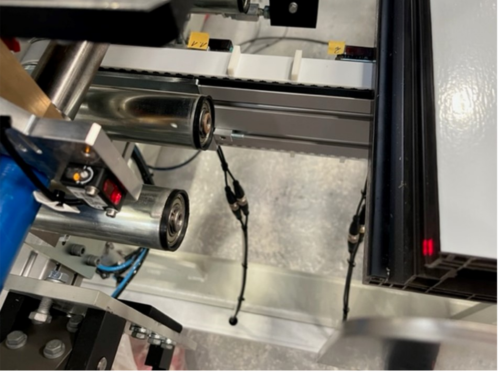
| + | |Description=<translate>Notes on Setting the measuring sensors on the Autoflow Mk4 Stuertz Infeed Table</translate> | ||
|Categories=Maintenance | |Categories=Maintenance | ||
}} | }} | ||
| Ligne 31 : | Ligne 33 : | ||
|} | |} | ||
| − | =Sensor Setting= | + | =General Procedure for Sensor Setting= |
| − | + | ||
| + | # Ensure the laser is not angled down - the beam must be horizontal | ||
| + | {{Info|...Angling the laser downwards may seem a great solution to reach lower profiles, but this will make it very difficult to set up a whole range of profiles. There is an adjustment for the measuring height in the software, but this is unusable if the sensor is angled down}} | ||
| + | # Ensure the minimum GZ position is reached and the head is at this position | ||
| + | # Ensure the Sensor is fitted with the adjustment screw at the top | ||
| + | # Ensure the profile indexer has been set up . [[Stuertz Conveyor Motor and Indexing Setup]] | ||
| + | {{Info|...This ensures that the profile is in the correct present position for the measuring routine}} | ||
| + | # Using the narrowest, darkest profile you can find, load the bar using the index button to the measuring position | ||
| + | # Move the GX axis via Drives tab to the measuring position (around -970mm). | ||
| + | # Disable the axis by pressing estop | ||
| + | # Adjust the sensor sensitivity so that it sees the brown profile, but switches off when you move it out of the way. | ||
| + | # Check it is not too sensitive by ensuring it does not pick up a bar at the front of the slot behind it | ||
| + | # Check the measureStartPosX is the correct place for the measuring to start. This should be just past the profile end plate | ||
| + | {{Warning|...All measurement positions are referenced from the datum position of the GX axis. Therefore they are completely dependent on it being correct. If you have to reset the GX datum or scaling by a considerable amount, it will affect this position and it may need to be changed. | ||
| + | The zero position should be the centreline of the spindles}}<br /> | ||
| − | |||
| − | |||
<br /></translate> | <br /></translate> | ||
{{PageLang | {{PageLang | ||
Version du 30 janvier 2023 à 22:26
Notes on Setting the measuring sensors on the Autoflow Mk4 Stuertz Infeed Table

Measure Start Positions
| Parameter | Description | Value | Notes |
|---|---|---|---|
| measureStartPosX | Start position in X axis for measure sensors |
-970 | Should be slightly to machining centre side of profile end stop |
| measureStartPosY | Default Gripper Y position for measuring
This can be changed from the default value for specific profiles in the parameter table |
30 | Will only make a difference if the measure sensor is angled |
| measureStartPosZ | Default Gripper height for measuring
This can be changed from the default value for specific profiles in the parameter table |
6 | Needs to go as low as possible because the profile sits lower down to the gripper (due to the lifting roller system)
|
General Procedure for Sensor Setting
- Ensure the laser is not angled down - the beam must be horizontal
- Ensure the minimum GZ position is reached and the head is at this position
- Ensure the Sensor is fitted with the adjustment screw at the top
- Ensure the profile indexer has been set up . Stuertz Conveyor Motor and Indexing Setup
- Using the narrowest, darkest profile you can find, load the bar using the index button to the measuring position
- Move the GX axis via Drives tab to the measuring position (around -970mm).
- Disable the axis by pressing estop
- Adjust the sensor sensitivity so that it sees the brown profile, but switches off when you move it out of the way.
- Check it is not too sensitive by ensuring it does not pick up a bar at the front of the slot behind it
- Check the measureStartPosX is the correct place for the measuring to start. This should be just past the profile end plate
Draft
 Français
 English
 Deutsch
 Español
 Italiano
 Português