On site upgrade of Flowline Mk3 with Beckhoff AX8000 drives, EtherCAT IO slices and TwinCAT 3 IPC.
Sommaire
- 1 Introduction
- 2 Étape 1 - Familiarisation
- 3 Étape 2 - Parts Identification and Rectification
- 4 Étape 3 - Health and Safety
- 5 Étape 4 - Removal of Components (MH Cabinet)
- 6 Étape 5 - Removal of Components (Saw Console)
- 7 Étape 6 - Removal of Components (Transfer Cabinet)
- 8 Étape 7 - Removal of Components (Motors and Gearboxes)
- 9 Étape 8 - Removal of Components (General)
- 10 Étape 9 - Adding New Components (MH Cabinet)
- 11 Étape 10 - Adding New Components (MH Cabinet) continued.
- 12 Étape 11 - Adding New Components (Saw Console)
- 13 Étape 12 - Adding New Components (Transfer Cabinet)
- 14 Étape 13 - Adding New Components (Motors and Gearboxes)
- 15 Étape 14 - Adding New Components (General)
- 16 Étape 15 - Adding Offcut Measuring*
- 17 Étape 16 - Adding Zero Speed Detector*
- 18 Commentaires
Introduction
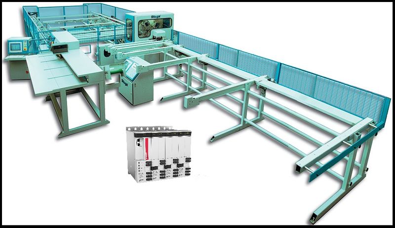
The Flowline Mk3 is a Stuga built and designed machine for prepping and cutting uPVC windows and doors. The Flowline is the first machine of the Stuga 'U' shaped machines which has prepping and cutting working in the same machine package. The Flowline is still a fantastic machine for the industry, however, due to the age of the machines and older control systems becoming obsolescent, we have had to find an upgrade route that does not only keep the machine going, but also provides improvements from the original model and up-to-date technology to future proof the machine.
The upgrade that we have developed for the Flowline is supplied from an automation supplier named Beckhoff. We also use Beckhoff on our new build machines. This gives us better lead times, more understanding of the products and better diagnpostics/ support for our customers. The drive system that we use is called the AX8000 series. These drives are a compact multi axis servo system that use an EtherCAT interface and STO saftey functions. These servo drives, coupled with Beckhoff AM8*** series OCT servo motors provide quicker installations and all round performance increases from any system we have previously used. To drive all of the new system, we are using a Beckhoff IPC controller that runs TwinCAT 3. This links into the system via EtherCAT. All of the machine can now link together via EtherCAT to provide quick and stable communications.
This tutorial will give you step by step guides on the physical upgrade requirements needed when upgrading a Flowline Mk3 to a Flowline Mk3 with Beckhoff AX8000 Control. Each step will provide you with written information and pictures to guide you through the upgrade. Each step will contain necessary information which will also provide you with rationale for the design and an idea of the benefits over using different methods.
- Fichiers
Étape 1 - Familiarisation
The first step does not involve being on site or carrying out any physical tasks. However, trying to gain some familiarisation before carrying out the upgrade can save time and confusion down the line.
Please read through this tutorial before upgrading the machine. The attached files and steps will walk you through the upgrade that somebody else has already experienced. This will give you a free look at any issues or learnings that have already been made.
Étape 2 - Parts Identification and Rectification
This upgrade is covered by BoM R0010201D. This BoM contains all of the parts necessary to complete the upgrade on the machine. This BoM has been created from previous upgrades and from the knowledge of Stuga engineers.
If any extra parts were identified at the time of ordering, they will appear on a seperate BoM for the specific machine build.
Parts will have been picked and checked at Stuga before despatch. However, the first step when arriving on site is to check that all of the parts have arrived and no parts have been damaged or misplaced. The BoM sheets for the parts will be in the boxes with the parts and should be used to cross reference what has been sent.
Attached to this document is a .pdf document of R0010201D that lists all the parts required to complete this upgrade.
If all parts have been cross referenced, move on to step 3. However, if some parts are missing or damaged, please report them to stugaparts@stuga.co.uk and send across the necessary information/ evidence so we can get parts to you. Once this has been sent, move onto step 3.
Étape 3 - Health and Safety
Before any work can be carried out on the machine. You must first ensure that you and the area that you are working in are safe.
Make sure that you ask the customer for their health and safety instructions including first aid and fire safety. Follow all of the health and safety instructions given to you by the customer and Stuga.
Before carrying out any work, ensure the machine is turned off, unplugged and locked off. DO NOT WORK ON LIVE ELECTRICS.
Étape 4 - Removal of Components (MH Cabinet)
List of components to be removed and unwired from the MH cabinet:
- Nextmove E100 - Remove the unit but keep the IO wiring in place as this is where the new IO slices will be wired.
- Nextmove cards (orange IO cards) - Remove the unit but keep the IO wiring in place as this is where the new IO slices will be wired.
- Samsung servo drives - Remove the drives, resistors and wiring.
- Baldor servo drives - Remove the drives, resistors and wiring.
- SA14 unit - Remove the drive and wiring.
- APC - Remove PC, unplug all serial devices, unplug VGA cable and RJ45 cable. The VGA cable will be reused so do not cut this.
- 4 off 10A single pole breakers - There will be 5 breakers in total but we keep 1 breaker in as spare to save time on rewiring the link wires at the top. We will add a 3 pole breaker (10A E0000291) and another single pole breaker further into the upgrade.
- Timer unit - This can be removed completely.
- Ethernet switch - This will be replaced with a newer model.
- Telephone modem - The can be removed completely.
All of the servo and stepper wiring can be removed from the cabinet. The glands that the servo cables enter the cabinet via can also be removed as the new servo cables are bigger.
Étape 5 - Removal of Components (Saw Console)
List of components to be removed and unwired from the Saw console cabinet:
- AcePC - Remove the PC and any wiring that is NOT on a 12 core cable that goes across to the Saw module. The wires that are part of a multicore cable need to be unwired ready for installation into the new IO slices.
- Nextmove ESB - Remove unit and wiring.
- Samsung servo drive - Remove unit and wiring.
- Baldor servo drive - Remove unit and wiring.
- Single pole 10A breaker - Remove wiring and take breaker out.
- Interface relays - All outputs will be +24Vdc switching. If valve bank polarity is incorrect, use an attached TB from Stuga.
- Serial cable for printer - The printer will now run on EtherNET straight from MH cabinet.
The servo drive cables can be removed at this stage. Cut them in half in the Transfer cabinet and pull the remainder through the conduit. These will not be reused. The new Saw Pusher cable terminats in the MH so does not need to be pulled through the conduit.
Étape 6 - Removal of Components (Transfer Cabinet)
List of components to remove from the Transfer cabinet:
- BandR PLC - Remove the unit but keep the wiring for the new IO slices.
- Omron PLC - Remove the unit but keep the wiring for the new IO slices.
- Interface Relays - Interface relays no longer needed so relays that interface 'saw and transfer' and 'transfer and multi' can be removed.
Étape 7 - Removal of Components (Motors and Gearboxes)
Étape 8 - Removal of Components (General)
List of general components to be removed:
- Monitor on MH side - This will be replaced with a touchscreen.
- Monitor on Saw side - This will be replaced with a screen (not touch).
- Keyboard from Saw side - This will be replaced with a bluetooth keyboard.
- Keyboard from MH side - This will be replaced with a keyboard and mouse combination.
- Mouse from MH side - Remove mouse. Will now be integrated into keyboard.
Étape 9 - Adding New Components (MH Cabinet)
List of new components to be added into MH cabinet:
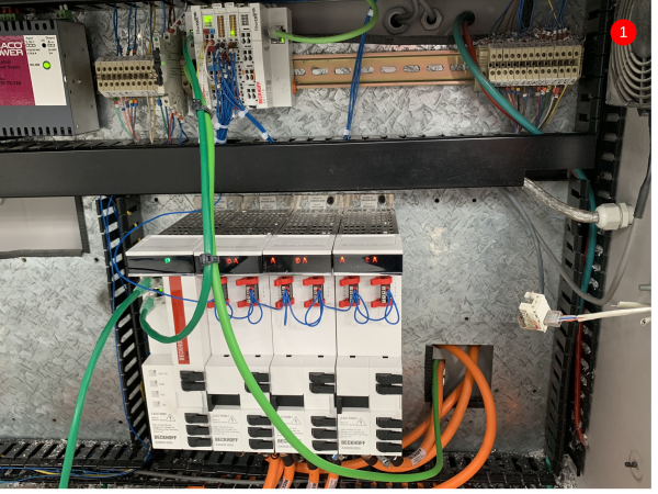
- Beckhoff AX8000 series drives. The drive block (item 1) consist of 4 different devices that all connect together. The first device is the PSU module. It is labelled AX8620. The other 3 devices are all AX8206 drives. These are dual channel servo drives and this is where the motor cables will wire into. Drill the PSU module onto the cabinet back plate and then connect each AX8206 drive individually to each other and drill them off. To connect the drives electrically, you simply push them into each other and slide across the middle connector and pop down the black plastic caps on the previous drive to lock them in place.
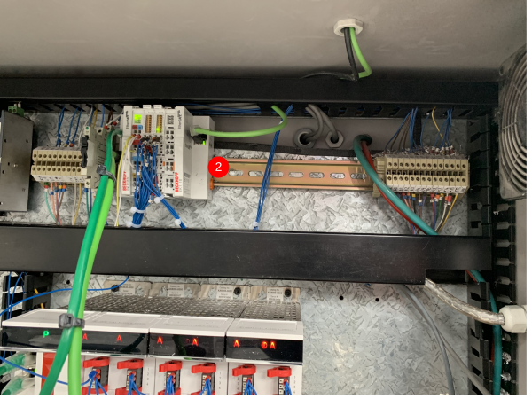
- Beckhoff EK series IO slices (item 2). These IO slices are labelled in the electrical drawings as 'Top Left of Cabinet'. The IO bank consists of 1 off EK1100 bus connector, 2 off EL1859 HDIO slices and 1 off EK1110 bus terminator. This bank of IO replaces all the IO wiring from the old Nextmove controller.
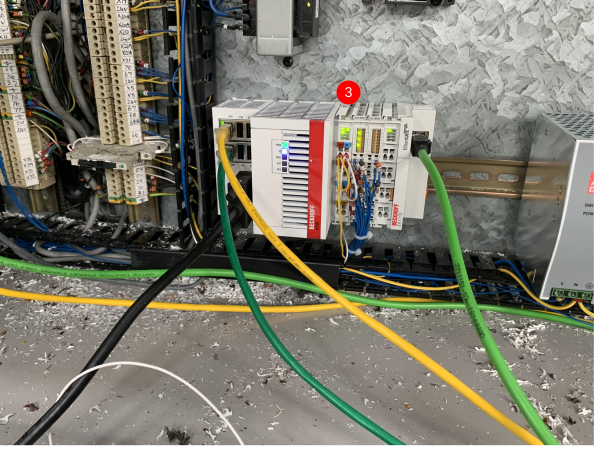
- Beckhoff IPC Machine Controller and IO (item 3). The IPC that controls the machine situates in the bottom left of the cabinet replacing the IO modules from the previous control system. Attached to the IPC is 2 off EL1859 HDIO slices and 1 off EK1110 bus terminator.
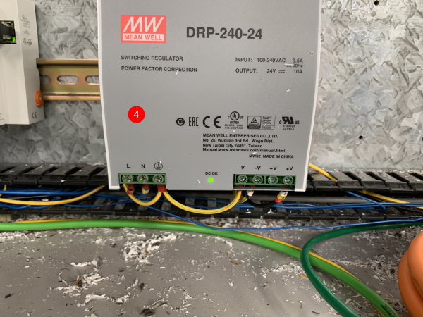
- Additional 24Vdc power supply for the AX8000 drives (item 4). This mounts on the DIN rail next to the 'bottom left' IO and IPC. This then wires into a new 3A 1pole breaker which needs to go in place of one of the breakers removed when the servo drives were removed.
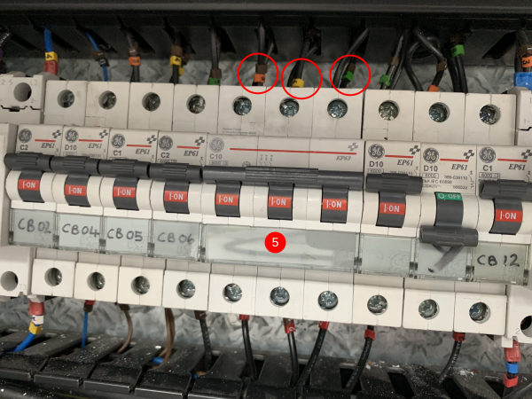
- 10A 3pole breaker for the AX8000 servo drives (item 5). This goes in place of 3 of the old servo single pole breakers. It is important to make sure the wires at the top are 3 individually phases (13,14 and 15).
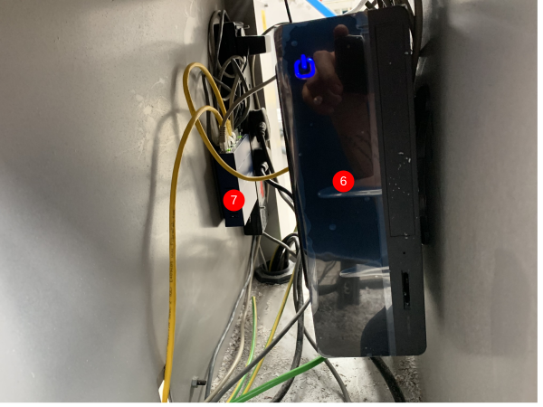
- New front end PC (item 6) needs to be drilled off into the inside of the AcePC enclosure. A new ethernet switch (item 7) needs to be fitted near the PC just using Velcro (this is supplied).
Étape 10 - Adding New Components (MH Cabinet) continued.
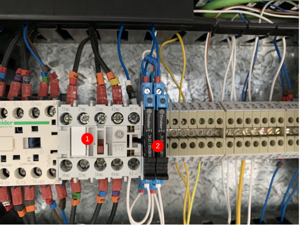
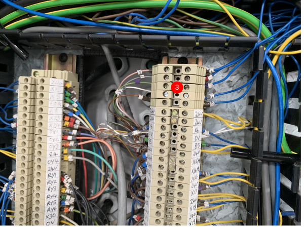
7. 2 24Vdc relays (item 2) need adding for the infeed motor and material load motor control. The 2 relays are activated by 0Vdv (A2) and 66 (A1). The switch side of both of the relays is 0Vdc (11) and Safe_0Vdc (14). The Safe_0Vdc wires go into A2 of the solid state relay and A2 of the new 24Vdc contactor (item 1). 8. The new 24Vdc contactor (item 1) replaces a 24Vac contactor. The original ac contactor had the same wiring in L1,L2,L3,T1,T2 and T3. However the coil was different. Remove the wiring from the old coil. It is no longer needed. Next to the old contactor is a 24Vdc relay which is controlled by Y10. Take the Y10 wire and but this in the new 24Vdc contactor A1. 9. Another new 24Vdc contactor needs adding inline with the 3 phase power for teh AX8000 drives. The contcator can be situated anywhere on the top DIN rail. The 3 wires that come out of the bottom of the 3pole breaker (point 5) need to go to L1,L2 and L3 of the new contactor. New 1mm black wires then need adding from T1,T2 and T3 that go to the AX8000 drives. The A1 of the contactor needs to be 66 and the A2 needs to be 0Vdc. 10. Any relays that are in the cabinet need to be checked for polarity and change where needed. On the old system, the relays were wired so the output from the PLC was in A2 and then A1 was 24Vdc. The outputs have now changed polarity so that the output from the PLC goes into A1 and then A2 is 0Vdc. Tip - if you look on the switch side of the relay and notice that the valve wire (for example) is switching across onto a 24Vdc wire, you can remove the relay completely and just use the output to drive the valve see (item 3).
Étape 11 - Adding New Components (Saw Console)
Étape 12 - Adding New Components (Transfer Cabinet)
Étape 13 - Adding New Components (Motors and Gearboxes)
Étape 14 - Adding New Components (General)
Anacondas, Networks, Touchscreens
Étape 15 - Adding Offcut Measuring*
Étape 16 - Adding Zero Speed Detector*
Draft
 Français
 English
 Deutsch
 Español
 Italiano
 Português