Due to the SR Axis losing its datum position an additional datum sensor is to be fitted.

Difficulté
Moyen
Durée
30 minute(s)
Sommaire
- 1 Introduction
- 2 Étape 1 - Fit U Bolt and Sensor Bar
- 3 Étape 2 - Remove 2x M8 screws
- 4 Étape 3 - Fit Flag and Bracket to Motor Plate with 2x M8 x 50 Screws
- 5 Étape 4 - Ensure Bracket is far right in the slots
- 6 Étape 5 - Check sensor is activated
- 7 Étape 6 - ELECTRICAL
- 8 Étape 7 - SOFTWARE SETUP
- 9 Commentaires
Introduction
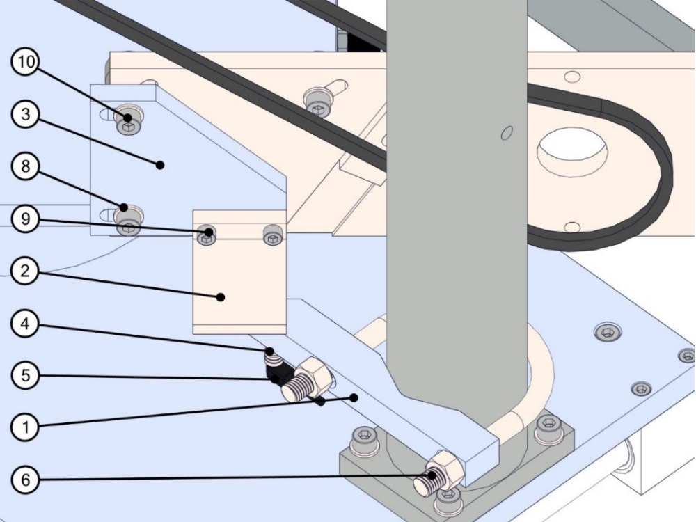
| Item Number | Part Number | Description | Qty |
| 1 | D0015489 | Saw Turntable Sensor Bar | 1 |
| 2 | D0015490 | Saw Turntable Sensor Flag | 1 |
| 3 | D0015491 | Saw Turntable Flag Bracket | 1 |
| 4 | E0000336 | 8mm Threaded Proximity Sensor | 1 |
| 5 | E0000337 | M8 90° Lead | 1 |
| 6 | F0000543 | U Bolt 3” with Nuts | 1 |
| 8 | F0000059 | M8 Washer | 2 |
| 9 | F0000014 | M6 x 20 SKT CAP SCREW | 2 |
| 10 | F0000028 | M8 x 50 SKT CAP SCREW | 2 |
Étape 1 - Fit U Bolt and Sensor Bar
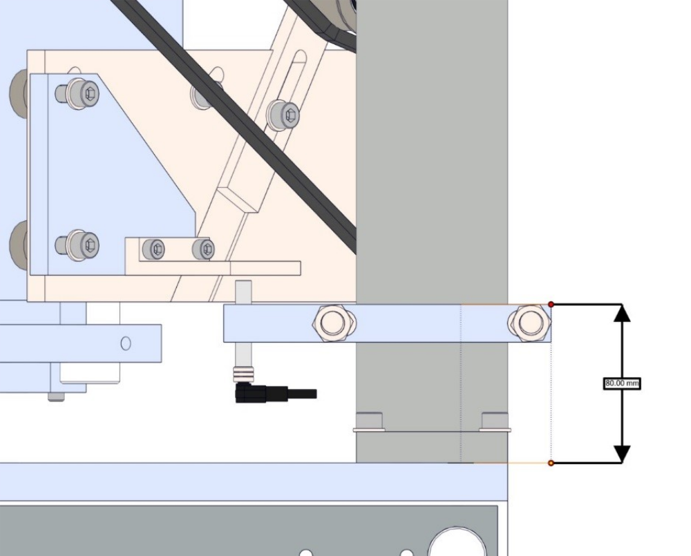
Fit U Bolt and Sensor Bar to Table Post on infeed side of saw. See Image for height
Étape 2 - Remove 2x M8 screws
Remove 2x M8 screws holding Motor Plate.
Étape 3 - Fit Flag and Bracket to Motor Plate with 2x M8 x 50 Screws
Fit Flag and Bracket to Motor Plate with 2x M8 x 50 Screws
Étape 4 - Ensure Bracket is far right in the slots
Ensure Bracket is far right in the slots and sensor flag is parallel to turntable base.
Étape 5 - Check sensor is activated
Check sensor is activated by the flag and stays on when turntable is in maximum position
Étape 6 - ELECTRICAL
Sensor wiring should be
| Cable Colour | IO Terminal X06 |
| Brown | 24v |
| Blue | 0v |
| Black | 0 |

Étape 7 - SOFTWARE SETUP
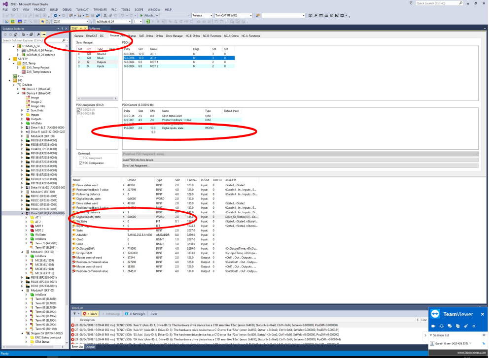
Drive must be set up to map IO values through to Drive_IO_Status[Axis] array. This is done in 2 steps
1. Add the Digital Inputs State PDO P-0-0801 to S-0-0016 for the SR drive. If a dual axis drive used, ensure you select the correct PDO from the PDO List as there is one for each axis. This is all in the Process Data tab.
2. Link the Digital inputs word to to Drive_IO_Status[9] – simply double click it in the list of IO for the drive
Draft
 Français
 English
 Deutsch
 Español
 Italiano
 Português