This page contains a PDF which details the reasons why and how to change the wiring and parameters for a Yaskawa Inverter to output a Fault and an Alarm signal.
Sommaire
The Yaskawa inverter has been set up to give us an alarm when the inverter is in fault. This input is X342, X90 or X27 (machine dependant) and can be found on the IO screen as InB_InvOk. This input is high when the inverter is Ok.
The inverter has internal settings which dictates what is considered a Fault or what is
considered an Alarm. There is an extensive list in the Yaskawa manual which explains what will
be displayed as an Alarm and what will be displayed as a Fault. See example screenshot below.
The issue that we have seen is when the inverter goes into Alarm, we do not lose the InB_InvOk input but the machine continues to try and machine. This is resulting in tool breakages and gripper damage. The real-life example of this is a machine that had 1 of the 2 STO relays fail and the inverter shut o with an STO alarm but the system did not know the inverter had shut off.
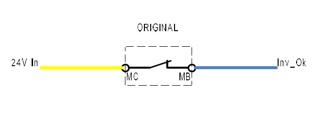
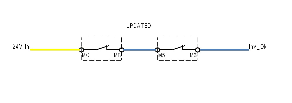
The fix for this issue is to use the Digital IO inside the inverter to switch when the inverter goes into Fault OR Alarm. Using the parameter table in the Yaskawa manual, we can select the functions of the Digital IO terminals, and these functions can either be Fault or Alarm but not both. By default, terminals MC, MB and MA are assigned to Fault. A spare output is available in the inverter (M5-M6) and we can use this for Alarm. Both outputs need to be NC and in series so that if either open, we will lose the InB_InvOk input.
Remove the wire from terminal MB and put it into terminal M6. Then add a link wire from MB to terminal M5.
This is a picture of the final result:
Once wiring changes have been made, change parameter H2-03 to 110. This can be done online via DriveWizard or directly through the
inverter touchpad.
Draft


 Français
 English
 Deutsch
 Español
 Italiano
 Português