| [version en cours de rédaction] | [version en cours de rédaction] |
(Page créée avec « {{Tuto Details |Main_Picture=TM018B_Microline_and_ZX3_V_Notch_Blade_Setup_ZX3_Ring.jpg |Main_Picture_annotation={"version":"2.4.6","objects":[{"type":"image","version":"2.... ») |
|||
| Ligne 37 : | Ligne 37 : | ||
{{EPI}} | {{EPI}} | ||
{{Tuto Step | {{Tuto Step | ||
| − | |Step_Title=<translate> | + | |Step_Title=<translate>Before You Start</translate> |
| − | |Step_Content=<translate></translate> | + | |Step_Content=<translate># Make sure the Datum is correct first. |
| + | # V notch blades are not buckled. | ||
| + | # Check that the profile width is correct for the profile you are testing.</translate> | ||
| + | }} | ||
| + | {{Tuto Step | ||
| + | |Step_Title=<translate>Run a VTest</translate> | ||
| + | |Step_Content=<translate>A calibration mnd file has been written to help line up the x offsets called VTEST. This program creates the following pattern on the bottom of the profile using a 10mm spindle and the notching blades themselves: | ||
| + | |||
| + | Run the VTest operation on a length of large outer frame of at least 1m long. Put the operation at a position of 500mm.</translate> | ||
}} | }} | ||
{{Notes}} | {{Notes}} | ||
{{PageLang | {{PageLang | ||
| + | |Language=en | ||
|SourceLanguage=none | |SourceLanguage=none | ||
|IsTranslation=0 | |IsTranslation=0 | ||
| − | |||
}} | }} | ||
{{Tuto Status | {{Tuto Status | ||
|Complete=Draft | |Complete=Draft | ||
}} | }} | ||
Version du 22 octobre 2019 à 10:41
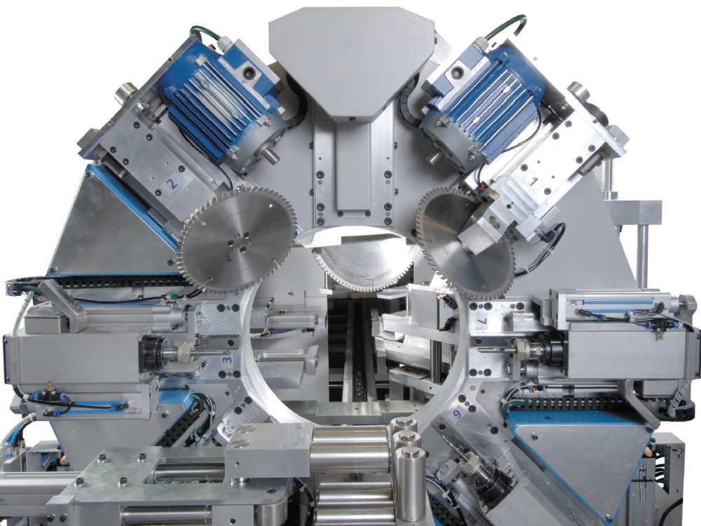
ZX3/Microline/Flowline ZX3 V Notch Blade Setup This module guides the engineer on how to correctly set the V notch blades

Difficulté
Difficile
Durée
30 minute(s)
Introduction
The engineer will need a reasonable mechanical knowledge, and a working knowledge of the operation of the machine.
You will need callipers (+/-0.05mm) and an accurate rule
The setting of the V notch blades on a ZX3 revolves around the setting of two groups of parameters:
- V and W axis positions
- Blade offsets for each blade
The rough position of V and W axes is set first, then the individual blade offsets are set, and finally a test is run to tweak the accuracy to gain perfection.
There are two “tweaking” parameters for each blade. The two parameters are:
- Depth offset – how deep into the bar
- X axis offset – position of point of blade relative to the spindle centreline
- Pièces et outils
Pièces et outils
150mm Caliper 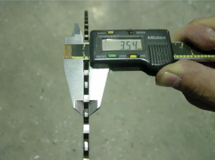

Digital or Analogue Calipers - Accurate to 0.01mm
150mm Rule 

150mm Rule
Étape 1 - Before You Start
- Make sure the Datum is correct first.
- V notch blades are not buckled.
- Check that the profile width is correct for the profile you are testing.
Étape 2 - Run a VTest
A calibration mnd file has been written to help line up the x offsets called VTEST. This program creates the following pattern on the bottom of the profile using a 10mm spindle and the notching blades themselves:
Run the VTest operation on a length of large outer frame of at least 1m long. Put the operation at a position of 500mm.
Draft
 Français
 English
 Deutsch
 Español
 Italiano
 Português