| [version en cours de rédaction] | [version en cours de rédaction] |
| Ligne 118 : | Ligne 118 : | ||
|Step_Content=<translate><br /> | |Step_Content=<translate><br /> | ||
| − | * 1 phase | + | *1 phase |
| − | * Neutral | + | *Neutral |
| − | * Earth | + | *Earth |
| − | * Fwd and Reverse signals | + | *Fwd and Reverse signals |
| + | *Wire motor cables directly to bottom of drives | ||
<br /></translate> | <br /></translate> | ||
| + | |Step_Picture_00=Fitting_Zx5_Crank_Upgrade_Module_C_Eaton_drives.JPG | ||
| + | |Step_Picture_00_annotation={"version":"2.4.6","objects":[{"type":"image","version":"2.4.6","originX":"left","originY":"top","left":28,"top":70,"width":1148,"height":609,"fill":"rgb(0,0,0)","stroke":null,"strokeWidth":0,"strokeDashArray":null,"strokeLineCap":"butt","strokeDashOffset":0,"strokeLineJoin":"miter","strokeMiterLimit":4,"scaleX":0.48,"scaleY":0.48,"angle":0,"flipX":false,"flipY":false,"opacity":1,"shadow":null,"visible":true,"clipTo":null,"backgroundColor":"","fillRule":"nonzero","paintFirst":"fill","globalCompositeOperation":"source-over","transformMatrix":null,"skewX":0,"skewY":0,"crossOrigin":"","cropX":0,"cropY":0,"src":"https://stuga.dokit.app/images/c/c3/Fitting_Zx5_Crank_Upgrade_Module_C_Eaton_drives.JPG","filters":[]}],"height":450.11286681715575,"width":600} | ||
| + | |Step_Picture_01=Fitting_Zx5_Crank_Upgrade_Module_E_Eaton_drive.JPG | ||
| + | |Step_Picture_01_annotation={"version":"2.4.6","objects":[{"type":"image","version":"2.4.6","originX":"left","originY":"top","left":146,"top":-1,"width":385,"height":637,"fill":"rgb(0,0,0)","stroke":null,"strokeWidth":0,"strokeDashArray":null,"strokeLineCap":"butt","strokeDashOffset":0,"strokeLineJoin":"miter","strokeMiterLimit":4,"scaleX":0.71,"scaleY":0.71,"angle":0,"flipX":false,"flipY":false,"opacity":1,"shadow":null,"visible":true,"clipTo":null,"backgroundColor":"","fillRule":"nonzero","paintFirst":"fill","globalCompositeOperation":"source-over","transformMatrix":null,"skewX":0,"skewY":0,"crossOrigin":"","cropX":0,"cropY":0,"src":"https://stuga.dokit.app/images/a/ae/Fitting_Zx5_Crank_Upgrade_Module_E_Eaton_drive.JPG","filters":[]}],"height":450,"width":600} | ||
| + | |Step_Picture_02=Fitting_Zx5_Crank_Upgrade_Module_C_control_wiring_for_Eaton_drives.JPG | ||
| + | |Step_Picture_02_annotation={"version":"2.4.6","objects":[{"type":"image","version":"2.4.6","originX":"left","originY":"top","left":84,"top":-3,"width":332,"height":363,"fill":"rgb(0,0,0)","stroke":null,"strokeWidth":0,"strokeDashArray":null,"strokeLineCap":"butt","strokeDashOffset":0,"strokeLineJoin":"miter","strokeMiterLimit":4,"scaleX":1.24,"scaleY":1.24,"angle":0,"flipX":false,"flipY":false,"opacity":1,"shadow":null,"visible":true,"clipTo":null,"backgroundColor":"","fillRule":"nonzero","paintFirst":"fill","globalCompositeOperation":"source-over","transformMatrix":null,"skewX":0,"skewY":0,"crossOrigin":"","cropX":0,"cropY":0,"src":"https://stuga.dokit.app/images/e/e1/Fitting_Zx5_Crank_Upgrade_Module_C_control_wiring_for_Eaton_drives.JPG","filters":[]}],"height":450,"width":600} | ||
| + | |Step_Picture_03=Fitting_Zx5_Crank_Upgrade_Module_E_control_wiring_for_Eaton_drive.JPG | ||
| + | |Step_Picture_03_annotation={"version":"2.4.6","objects":[{"type":"image","version":"2.4.6","originX":"left","originY":"top","left":103,"top":0,"width":260,"height":357,"fill":"rgb(0,0,0)","stroke":null,"strokeWidth":0,"strokeDashArray":null,"strokeLineCap":"butt","strokeDashOffset":0,"strokeLineJoin":"miter","strokeMiterLimit":4,"scaleX":1.26,"scaleY":1.26,"angle":0,"flipX":false,"flipY":false,"opacity":1,"shadow":null,"visible":true,"clipTo":null,"backgroundColor":"","fillRule":"nonzero","paintFirst":"fill","globalCompositeOperation":"source-over","transformMatrix":null,"skewX":0,"skewY":0,"crossOrigin":"","cropX":0,"cropY":0,"src":"https://stuga.dokit.app/images/e/eb/Fitting_Zx5_Crank_Upgrade_Module_E_control_wiring_for_Eaton_drive.JPG","filters":[]}],"height":450,"width":600} | ||
}} | }} | ||
{{Tuto Step | {{Tuto Step | ||
| − | |Step_Title=<translate>Wire | + | |Step_Title=<translate>Wire Sensor Cables to EtherCAT boxes</translate> |
| − | |Step_Content=<translate></translate> | + | |Step_Content=<translate>Module C and D cranks to back of Module C cabinet |
| + | |||
| + | Module E crank to back of Module E cabinet</translate> | ||
| + | |Step_Picture_00=Fitting_Zx5_Crank_Upgrade_FB01E_wiring_for_crank_upgrade.JPG | ||
| + | |Step_Picture_01=Fitting_Zx5_Crank_Upgrade_FB03C_wiring_for_crank_upgade.JPG | ||
}} | }} | ||
{{Tuto Step | {{Tuto Step | ||
Version du 23 septembre 2019 à 16:45
Fitting the crank upgrade to Z065, Z066, Z067

Difficulté
Difficile
Durée
2 jour(s)
Sommaire
- 1 Introduction
- 2 Étape 1 - Program Eaton Drives before they leave
- 3 Étape 2 - Remove Link arm connecting to rack and pinion
- 4 Étape 3 - Undo clutch and remove Cam
- 5 Étape 4 - Remove pivot shaft and arm
- 6 Étape 5 - Add sprocket to clutch
- 7 Étape 6 - Fix idler plate to upright
- 8 Étape 7 - Attach idler to plate
- 9 Étape 8 - Fix split sprocket onto drive shaft
- 10 Étape 9 - Drill and pin split sprocket to shaft
- 11 Étape 10 - Add chain minimum length sprocket to sprocket
- 12 Étape 11 - Fit Module C Crank Home sensor plate to Arm 5
- 13 Étape 12 - Fit Module C Crank Out sensor plate to Arm 5
- 14 Étape 13 - Fit Module D Crank Home sensor plate to Arm 5
- 15 Étape 14 - Fit Module D Crank Out sensor plate to Arm 5
- 16 Étape 15 - Fit Module E Crank Home sensor plate to Arm 5
- 17 Étape 16 - Fit Module E Crank Out sensor plate to Arm 5
- 18 Étape 17 - Remove 2 off breaker and contactor Module C
- 19 Étape 18 - Add 2 off single pole breaker Module C
- 20 Étape 19 - Add 2 off Eaton Drive to Module C
- 21 Étape 20 - Add single pole breaker Module E
- 22 Étape 21 - Remove breaker and contactor Module E
- 23 Étape 22 - Add 1 Off Eaton drive to Module E
- 24 Étape 23 - For each Eaton Drive
- 25 Étape 24 - Wire Sensor Cables to EtherCAT boxes
- 26 Étape 25 - Latest software installed
- 27 Étape 26 - Map new Links
- 28 Étape 27 - Test
- 29 Commentaires
Introduction
This upgrade replaces the crank arm assemblies on Z065, Z066 and Z067 with a direct drive system to improve reliability
Étape 1 - Program Eaton Drives before they leave
Running frequency
Control mode
Accel time
Decel time
Étape 2 - Remove Link arm connecting to rack and pinion
Étape 3 - Undo clutch and remove Cam
Étape 4 - Remove pivot shaft and arm
Étape 5 - Add sprocket to clutch
B0001166
Étape 6 - Fix idler plate to upright
Étape 7 - Attach idler to plate
Étape 8 - Fix split sprocket onto drive shaft
Étape 9 - Drill and pin split sprocket to shaft
Étape 10 - Add chain minimum length sprocket to sprocket
Use idler to create tension
Étape 11 - Fit Module C Crank Home sensor plate to Arm 5
Sensor cables run to rear Module C cabinet - EtherCAT fieldbus boxes
Étape 12 - Fit Module C Crank Out sensor plate to Arm 5
This one has an extension
Sensor cables run to rear Module C cabinet - EtherCAT fieldbus boxes
Étape 13 - Fit Module D Crank Home sensor plate to Arm 5
Sensor cables run to rear Module C cabinet - EtherCAT fieldbus boxes
Étape 14 - Fit Module D Crank Out sensor plate to Arm 5
This one has an extension
Sensor cables run to rear Module C cabinet - EtherCAT fieldbus boxes
Étape 15 - Fit Module E Crank Home sensor plate to Arm 5
This one has an extension
Sensor cables run to rear Module E cabinet - EtherCAT fieldbus boxes
Étape 16 - Fit Module E Crank Out sensor plate to Arm 5
Sensor cables run to rear Module E cabinet - EtherCAT fieldbus boxes
Étape 17 - Remove 2 off breaker and contactor Module C
Étape 18 - Add 2 off single pole breaker Module C
Tidy wires away for the spare 2 phases
Étape 19 - Add 2 off Eaton Drive to Module C
May need to move trunking
Étape 20 - Add single pole breaker Module E
Étape 21 - Remove breaker and contactor Module E
Étape 22 - Add 1 Off Eaton drive to Module E
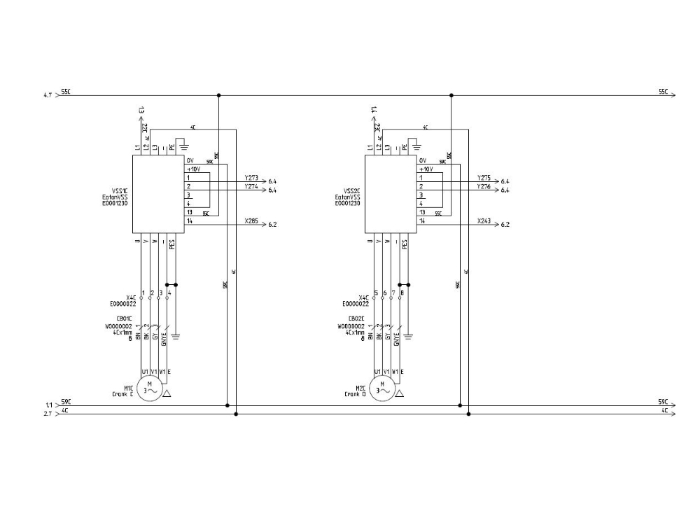
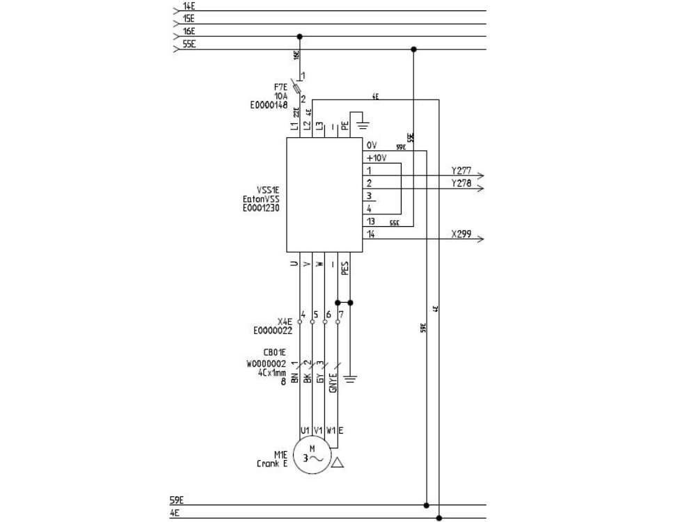
Étape 23 - For each Eaton Drive
- 1 phase
- Neutral
- Earth
- Fwd and Reverse signals
- Wire motor cables directly to bottom of drives
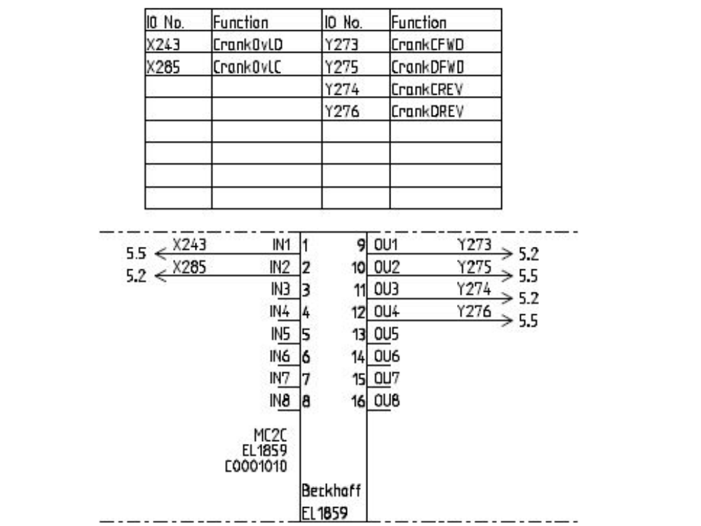
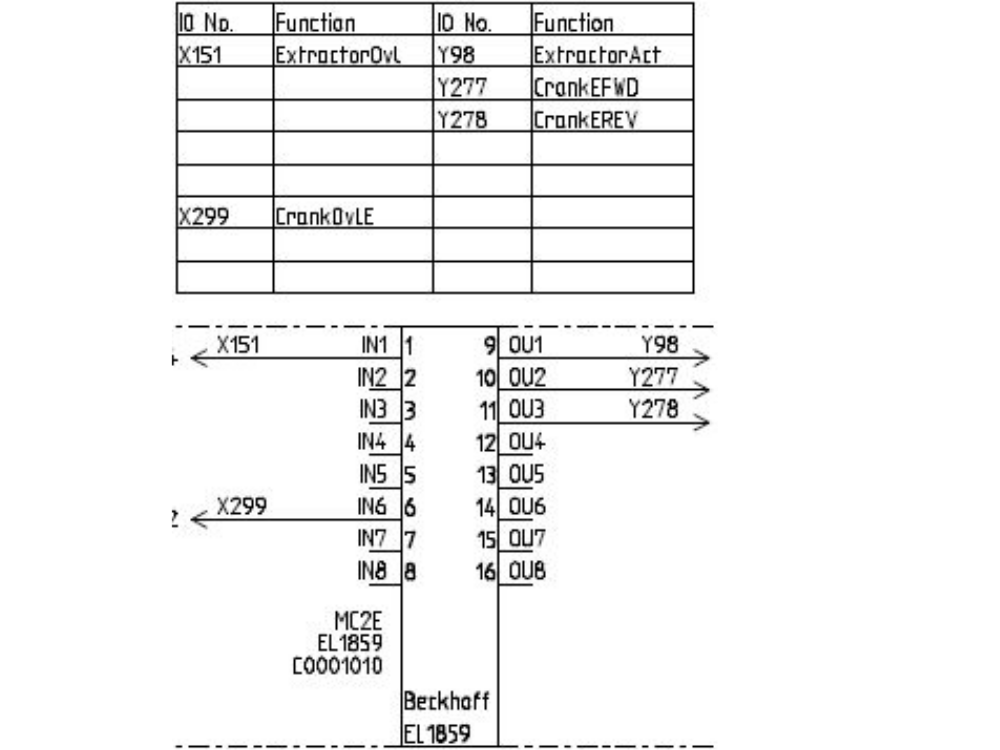
Étape 24 - Wire Sensor Cables to EtherCAT boxes
Module C and D cranks to back of Module C cabinet
Module E crank to back of Module E cabinet


Étape 25 - Latest software installed
Étape 26 - Map new Links
Étape 27 - Test
Draft
 Français
 English
 Deutsch
 Español
 Italiano
 Português