| [version en cours de rédaction] | [version en cours de rédaction] |
| Ligne 16 : | Ligne 16 : | ||
| − | The setting of the V notch blades on a ZX3 revolves around the setting of two groups of parameters: | + | The setting of the V notch blades on a ZX3 Ring revolves around the setting of two groups of parameters: |
| − | * V and W axis positions | + | *V and W axis positions |
| − | * Blade offsets for each blade | + | *Blade offsets for each blade |
The rough position of V and W axes is set first, then the individual blade offsets are set, and finally a test is run to tweak the accuracy to gain perfection. | The rough position of V and W axes is set first, then the individual blade offsets are set, and finally a test is run to tweak the accuracy to gain perfection. | ||
| Ligne 25 : | Ligne 25 : | ||
There are two “tweaking” parameters for each blade. The two parameters are: | There are two “tweaking” parameters for each blade. The two parameters are: | ||
| − | * Depth offset – how deep into the bar | + | *Depth offset – how deep into the bar |
| − | * X axis offset – position of point of blade relative to the spindle centreline</translate> | + | *X axis offset – position of point of blade relative to the spindle centreline</translate> |
}} | }} | ||
{{Materials | {{Materials | ||
| Ligne 40 : | Ligne 40 : | ||
|Step_Content=<translate>#Make sure the Datum is correct first. | |Step_Content=<translate>#Make sure the Datum is correct first. | ||
#V notch blades are not buckled. | #V notch blades are not buckled. | ||
| − | #Check that the profile width is correct for the profile you are testing.</translate> | + | #Check that the profile width is correct for the profile you are testing. |
| + | |||
| + | |||
| + | Find out which V Notch files the machine is using by checking the operation setup. A simple way of doing this is shown in the pictures. | ||
| + | |||
| + | Picture 1 - shows this machine uses VF / VR codes | ||
| + | |||
| + | Picture 2 - shows a different machine using VAF3 codes | ||
| + | |||
| + | Note this "mnd type" for later | ||
| + | |||
| + | {{Info|...The VF... codes are the original method of setting up the machines, the VAF3 codes are seen as an improvement because it makes the naming of the variables for the offsets a little clearer and groups them together. It also improves the machine cycle time by allowing the use of startOffset - the x axis needs to move only once to the start of the V notch}}<br /></translate> | ||
}} | }} | ||
{{Tuto Step | {{Tuto Step | ||
| Ligne 66 : | Ligne 77 : | ||
{{Tuto Step | {{Tuto Step | ||
|Step_Title=<translate>Update the Parameters for xOffsets</translate> | |Step_Title=<translate>Update the Parameters for xOffsets</translate> | ||
| − | |Step_Content=<translate># Set the xOffsetVI and WI to the new value | + | |Step_Content=<translate>#Set the xOffsetVI and WI to the new value settings. THIS VALUE IS ALWAYS POSITIVE |
| − | # Set the xOffsetVO and WO to the new value in | + | #Set the xOffsetVO and WO to the new value in settings. THIS VALUE IS ALWAYS NEGATIVE |
| + | |||
| + | |||
| + | Depending on the software version, there are 4 places where these settings are stored / edited | ||
| + | |||
| + | {| class="wikitable" | ||
| + | |+ | ||
| + | !Software Version | ||
| + | !mnd Type | ||
| + | !Parameter location | ||
| + | !Pic | ||
| + | |- | ||
| + | |Multi.exe (DOS) | ||
| + | |VF / VR | ||
| + | |Parameters (params.saw file) | ||
| + | |1 | ||
| + | |- | ||
| + | |winMulti v1-4 | ||
| + | |VF / VR | ||
| + | |Tooling Setup and params.mul | ||
| + | |2 | ||
| + | |- | ||
| + | |winMulti v1-4 | ||
| + | |VAF3 | ||
| + | |userVariables.mul | ||
| + | | | ||
| + | |- | ||
| + | |wimMulti v5+ | ||
| + | |VAF3 | ||
| + | |Settings->Notching Tab | ||
| + | |3 | ||
| + | |} | ||
<br /><syntaxhighlight> | <br /><syntaxhighlight> | ||
xOffsetVO=-87.59 | xOffsetVO=-87.59 | ||
Version du 22 octobre 2019 à 12:03
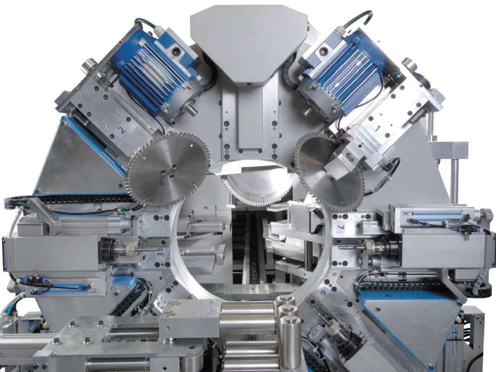
ZX3/Microline/Flowline ZX3 V Notch Blade Setup This module guides the engineer on how to correctly set the V notch blades

Difficulté
Difficile
Durée
30 minute(s)
Introduction
The engineer will need a reasonable mechanical knowledge, and a working knowledge of the operation of the machine.
You will need callipers (+/-0.05mm) and an accurate rule
The setting of the V notch blades on a ZX3 Ring revolves around the setting of two groups of parameters:
- V and W axis positions
- Blade offsets for each blade
The rough position of V and W axes is set first, then the individual blade offsets are set, and finally a test is run to tweak the accuracy to gain perfection.
There are two “tweaking” parameters for each blade. The two parameters are:
- Depth offset – how deep into the bar
- X axis offset – position of point of blade relative to the spindle centreline
- Pièces et outils
Pièces et outils
150mm Caliper 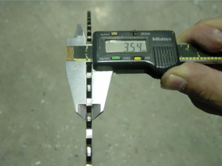

Digital or Analogue Calipers - Accurate to 0.01mm
150mm Rule 

150mm Rule
Étape 1 - Before You Start
- Make sure the Datum is correct first.
- V notch blades are not buckled.
- Check that the profile width is correct for the profile you are testing.
Find out which V Notch files the machine is using by checking the operation setup. A simple way of doing this is shown in the pictures.
Picture 1 - shows this machine uses VF / VR codes
Picture 2 - shows a different machine using VAF3 codes
Note this "mnd type" for later
Étape 2 - Run a VTest
A calibration mnd file has been written to help line up the x offsets called VTEST. This program creates the following pattern on the bottom of the profile using a 10mm spindle and the notching blades themselves:
Run the VTest operation on a length of large outer frame of at least 1m long. Put the operation at a position of 500mm.
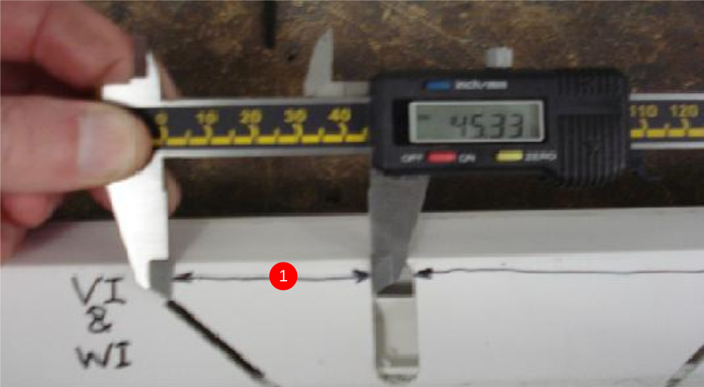
The pattern allows you to measure the offsets required with calipers.

Étape 3 - Measure Results for x Offsets
- Measure between the VI blade and the edge of the 10mm slot – This value is the xoffsetVI (and also the xoffsetWI). (We need to add 5mm to the measured Value). 50.33mm
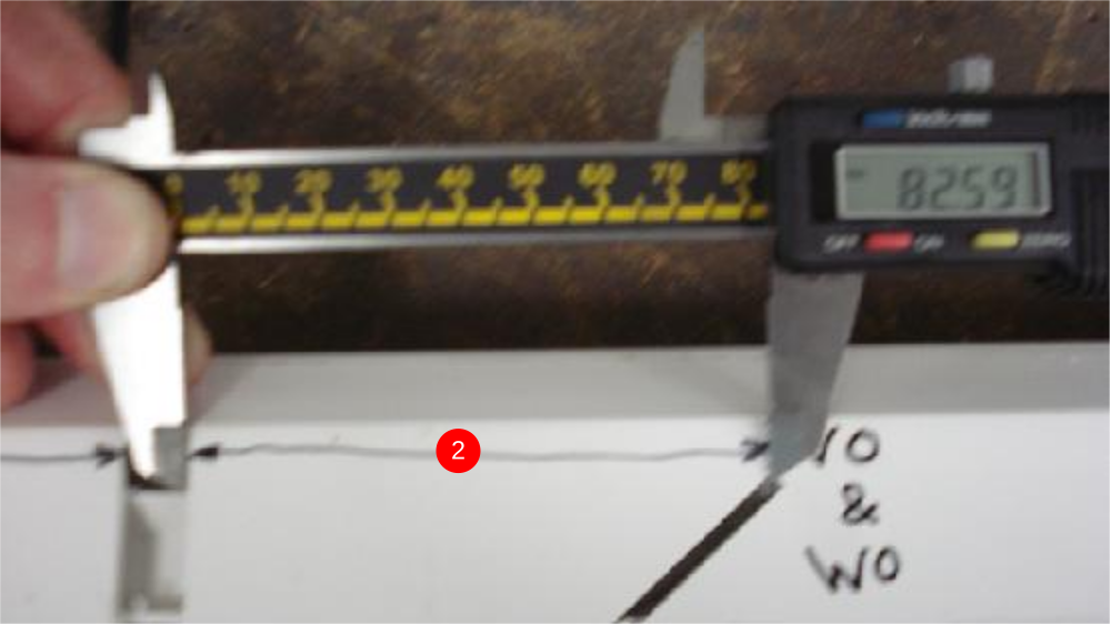
- Measure between the VO blade and the edge of the 10mm slot – This value is the xoffsetVO (and also the xoffsetWO). (We need to add 5mm to the measured Value) 87.59mm
Étape 4 - Update the Parameters for xOffsets
- Set the xOffsetVI and WI to the new value settings. THIS VALUE IS ALWAYS POSITIVE
- Set the xOffsetVO and WO to the new value in settings. THIS VALUE IS ALWAYS NEGATIVE
Depending on the software version, there are 4 places where these settings are stored / edited
| Software Version | mnd Type | Parameter location | Pic |
|---|---|---|---|
| Multi.exe (DOS) | VF / VR | Parameters (params.saw file) | 1 |
| winMulti v1-4 | VF / VR | Tooling Setup and params.mul | 2 |
| winMulti v1-4 | VAF3 | userVariables.mul | |
| wimMulti v5+ | VAF3 | Settings->Notching Tab | 3 |
xOffsetVO=-87.59
xOffsetVI=50.33
xOffsetWO=-87.59
xOffsetWI=50.33
Vtest is now done and Vcomp now needs to be run to set the depth of blades.
Draft
 Français
 English
 Deutsch
 Español
 Italiano
 Português