| [version en cours de rédaction] | [version en cours de rédaction] |
| Ligne 38 : | Ligne 38 : | ||
{{Tuto Step | {{Tuto Step | ||
|Step_Title=<translate>Before You Start</translate> | |Step_Title=<translate>Before You Start</translate> | ||
| − | |Step_Content=<translate># Make sure the Datum is correct first. | + | |Step_Content=<translate>#Make sure the Datum is correct first. |
| − | # V notch blades are not buckled. | + | #V notch blades are not buckled. |
| − | # Check that the profile width is correct for the profile you are testing.</translate> | + | #Check that the profile width is correct for the profile you are testing.</translate> |
}} | }} | ||
{{Tuto Step | {{Tuto Step | ||
| Ligne 46 : | Ligne 46 : | ||
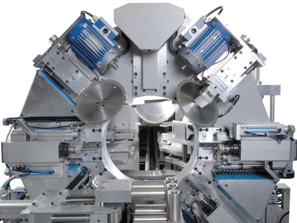
|Step_Content=<translate>A calibration mnd file has been written to help line up the x offsets called VTEST. This program creates the following pattern on the bottom of the profile using a 10mm spindle and the notching blades themselves: | |Step_Content=<translate>A calibration mnd file has been written to help line up the x offsets called VTEST. This program creates the following pattern on the bottom of the profile using a 10mm spindle and the notching blades themselves: | ||
| − | Run the VTest operation on a length of large outer frame of at least 1m long. Put the operation at a position of 500mm.</translate> | + | Run the VTest operation on a length of large outer frame of at least 1m long. Put the operation at a position of 500mm. |
| + | |||
| + | |||
| + | The pattern allows you to measure the offsets required with calipers. | ||
| + | |||
| + | <br />{{Info|...Profile is viewed from the bottom face, Basically turn it over when it comes of the transfer table.}}<br /></translate> | ||
| + | |Step_Picture_00=TM018B_Microline_and_ZX3_V_Notch_Blade_Setup_image1.jpeg | ||
| + | }} | ||
| + | {{Tuto Step | ||
| + | |Step_Title=<translate>Measure Results for x Offsets</translate> | ||
| + | |Step_Content=<translate># Measure between the VI blade and the edge of the 10mm slot – This value is the xoffsetVI (and also the xoffsetWI). (We need to add 5mm to the measured Value). ''' 50.33mm''' | ||
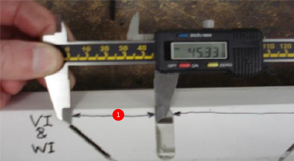
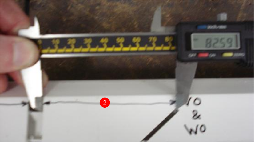
| + | # Measure between the VO blade and the edge of the 10mm slot – This value is the xoffsetVO (and also the xoffsetWO). (We need to add 5mm to the measured Value) '''87.59mm''' | ||
| + | {{Info|...The 5mm is added becasue this is half the 10mm slot width - thus measuring to the centreline of the slot}}<br /></translate> | ||
| + | |Step_Picture_00=TM018B_Microline_and_ZX3_V_Notch_Blade_Setup_image2.jpeg | ||
| + | |Step_Picture_00_annotation={"version":"2.4.6","objects":[{"type":"image","version":"2.4.6","originX":"left","originY":"top","left":0,"top":0,"width":538,"height":296,"fill":"rgb(0,0,0)","stroke":null,"strokeWidth":0,"strokeDashArray":null,"strokeLineCap":"butt","strokeDashOffset":0,"strokeLineJoin":"miter","strokeMiterLimit":4,"scaleX":1.12,"scaleY":1.12,"angle":0,"flipX":false,"flipY":false,"opacity":1,"shadow":null,"visible":true,"clipTo":null,"backgroundColor":"","fillRule":"nonzero","paintFirst":"fill","globalCompositeOperation":"source-over","transformMatrix":null,"skewX":0,"skewY":0,"crossOrigin":"","cropX":0,"cropY":0,"src":"https://stuga.dokit.app/images/4/46/TM018B_Microline_and_ZX3_V_Notch_Blade_Setup_image2.jpeg","filters":[]},{"type":"wfnumberedbullet","version":"2.4.6","originX":"left","originY":"top","left":229,"top":223,"width":25,"height":25,"fill":"rgb(0,0,0)","stroke":"#FF0000","strokeWidth":0,"strokeDashArray":null,"strokeLineCap":"butt","strokeDashOffset":0,"strokeLineJoin":"miter","strokeMiterLimit":4,"scaleX":1,"scaleY":1,"angle":0,"flipX":false,"flipY":false,"opacity":1,"shadow":null,"visible":true,"clipTo":null,"backgroundColor":"","fillRule":"nonzero","paintFirst":"fill","globalCompositeOperation":"source-over","transformMatrix":null,"skewX":0,"skewY":0,"objects":[{"type":"circle","version":"2.4.6","originX":"center","originY":"center","left":0,"top":0,"width":24,"height":24,"fill":"#FF0000","stroke":null,"strokeWidth":1,"strokeDashArray":null,"strokeLineCap":"butt","strokeDashOffset":0,"strokeLineJoin":"miter","strokeMiterLimit":4,"scaleX":1,"scaleY":1,"angle":0,"flipX":false,"flipY":false,"opacity":1,"shadow":null,"visible":true,"clipTo":null,"backgroundColor":"","fillRule":"nonzero","paintFirst":"fill","globalCompositeOperation":"source-over","transformMatrix":null,"skewX":0,"skewY":0,"radius":12,"startAngle":0,"endAngle":6.283185307179586},{"type":"text","version":"2.4.6","originX":"center","originY":"center","left":0,"top":0,"width":7.79,"height":15.82,"fill":"rgba(255,255,255,255)","stroke":null,"strokeWidth":1,"strokeDashArray":null,"strokeLineCap":"butt","strokeDashOffset":0,"strokeLineJoin":"miter","strokeMiterLimit":4,"scaleX":1,"scaleY":1,"angle":0,"flipX":false,"flipY":false,"opacity":1,"shadow":null,"visible":true,"clipTo":null,"backgroundColor":"","fillRule":"nonzero","paintFirst":"fill","globalCompositeOperation":"source-over","transformMatrix":null,"skewX":0,"skewY":0,"text":"1","fontSize":14,"fontWeight":"normal","fontFamily":"arial","fontStyle":"normal","lineHeight":1.16,"underline":false,"overline":false,"linethrough":false,"textAlign":"left","textBackgroundColor":"","charSpacing":0,"styles":{} }],"number":1}],"height":330,"width":600} | ||
| + | |Step_Picture_01=TM018B_Microline_and_ZX3_V_Notch_Blade_Setup_image3.jpeg | ||
| + | |Step_Picture_01_annotation={"version":"2.4.6","objects":[{"type":"image","version":"2.4.6","originX":"left","originY":"top","left":0,"top":0,"width":555,"height":312,"fill":"rgb(0,0,0)","stroke":null,"strokeWidth":0,"strokeDashArray":null,"strokeLineCap":"butt","strokeDashOffset":0,"strokeLineJoin":"miter","strokeMiterLimit":4,"scaleX":1.08,"scaleY":1.08,"angle":0,"flipX":false,"flipY":false,"opacity":1,"shadow":null,"visible":true,"clipTo":null,"backgroundColor":"","fillRule":"nonzero","paintFirst":"fill","globalCompositeOperation":"source-over","transformMatrix":null,"skewX":0,"skewY":0,"crossOrigin":"","cropX":0,"cropY":0,"src":"https://stuga.dokit.app/images/e/e3/TM018B_Microline_and_ZX3_V_Notch_Blade_Setup_image3.jpeg","filters":[]},{"type":"wfnumberedbullet","version":"2.4.6","originX":"left","originY":"top","left":235,"top":231,"width":25,"height":25,"fill":"rgb(0,0,0)","stroke":"#FF0000","strokeWidth":0,"strokeDashArray":null,"strokeLineCap":"butt","strokeDashOffset":0,"strokeLineJoin":"miter","strokeMiterLimit":4,"scaleX":1,"scaleY":1,"angle":0,"flipX":false,"flipY":false,"opacity":1,"shadow":null,"visible":true,"clipTo":null,"backgroundColor":"","fillRule":"nonzero","paintFirst":"fill","globalCompositeOperation":"source-over","transformMatrix":null,"skewX":0,"skewY":0,"objects":[{"type":"circle","version":"2.4.6","originX":"center","originY":"center","left":0,"top":0,"width":24,"height":24,"fill":"#FF0000","stroke":null,"strokeWidth":1,"strokeDashArray":null,"strokeLineCap":"butt","strokeDashOffset":0,"strokeLineJoin":"miter","strokeMiterLimit":4,"scaleX":1,"scaleY":1,"angle":0,"flipX":false,"flipY":false,"opacity":1,"shadow":null,"visible":true,"clipTo":null,"backgroundColor":"","fillRule":"nonzero","paintFirst":"fill","globalCompositeOperation":"source-over","transformMatrix":null,"skewX":0,"skewY":0,"radius":12,"startAngle":0,"endAngle":6.283185307179586},{"type":"text","version":"2.4.6","originX":"center","originY":"center","left":0,"top":0,"width":7.79,"height":15.82,"fill":"rgba(255,255,255,255)","stroke":null,"strokeWidth":1,"strokeDashArray":null,"strokeLineCap":"butt","strokeDashOffset":0,"strokeLineJoin":"miter","strokeMiterLimit":4,"scaleX":1,"scaleY":1,"angle":0,"flipX":false,"flipY":false,"opacity":1,"shadow":null,"visible":true,"clipTo":null,"backgroundColor":"","fillRule":"nonzero","paintFirst":"fill","globalCompositeOperation":"source-over","transformMatrix":null,"skewX":0,"skewY":0,"text":"2","fontSize":14,"fontWeight":"normal","fontFamily":"arial","fontStyle":"normal","lineHeight":1.16,"underline":false,"overline":false,"linethrough":false,"textAlign":"left","textBackgroundColor":"","charSpacing":0,"styles":{} }],"number":2}],"height":337,"width":600} | ||
| + | }} | ||
| + | {{Tuto Step | ||
| + | |Step_Title=<translate>Update the Parameters for xOffsets</translate> | ||
| + | |Step_Content=<translate># Set the xOffsetVI and WI to the new value in params.mul or Measurements in Neuron Settings. THIS VALUE IS ALWAYS POSITIVE | ||
| + | # Set the xOffsetVO and WO to the new value in params.mul or Measurements in Neuron Settings. THIS VALUE IS ALWAYS NEGATIVE | ||
| + | |||
| + | <br /><syntaxhighlight> | ||
| + | xOffsetVO=-87.59 | ||
| + | xOffsetVI=50.33 | ||
| + | xOffsetWO=-87.59 | ||
| + | xOffsetWI=50.33 | ||
| + | </syntaxhighlight> | ||
| + | |||
| + | |||
| + | Vtest is now done and Vcomp now needs to be run to set the depth of blades.</translate> | ||
}} | }} | ||
{{Notes}} | {{Notes}} | ||
Version du 22 octobre 2019 à 11:26
ZX3/Microline/Flowline ZX3 V Notch Blade Setup This module guides the engineer on how to correctly set the V notch blades

Difficulté
Difficile
Durée
30 minute(s)
Introduction
The engineer will need a reasonable mechanical knowledge, and a working knowledge of the operation of the machine.
You will need callipers (+/-0.05mm) and an accurate rule
The setting of the V notch blades on a ZX3 revolves around the setting of two groups of parameters:
- V and W axis positions
- Blade offsets for each blade
The rough position of V and W axes is set first, then the individual blade offsets are set, and finally a test is run to tweak the accuracy to gain perfection.
There are two “tweaking” parameters for each blade. The two parameters are:
- Depth offset – how deep into the bar
- X axis offset – position of point of blade relative to the spindle centreline
- Pièces et outils
Pièces et outils
150mm Caliper 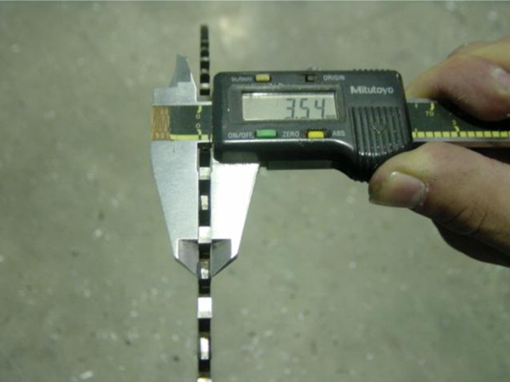

Digital or Analogue Calipers - Accurate to 0.01mm
150mm Rule 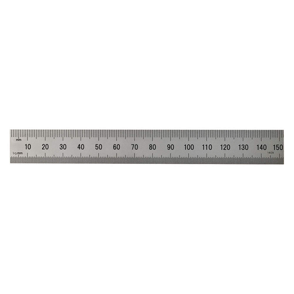

150mm Rule
Étape 1 - Before You Start
- Make sure the Datum is correct first.
- V notch blades are not buckled.
- Check that the profile width is correct for the profile you are testing.
Étape 2 - Run a VTest
A calibration mnd file has been written to help line up the x offsets called VTEST. This program creates the following pattern on the bottom of the profile using a 10mm spindle and the notching blades themselves:
Run the VTest operation on a length of large outer frame of at least 1m long. Put the operation at a position of 500mm.
The pattern allows you to measure the offsets required with calipers.

Étape 3 - Measure Results for x Offsets
- Measure between the VI blade and the edge of the 10mm slot – This value is the xoffsetVI (and also the xoffsetWI). (We need to add 5mm to the measured Value). 50.33mm
- Measure between the VO blade and the edge of the 10mm slot – This value is the xoffsetVO (and also the xoffsetWO). (We need to add 5mm to the measured Value) 87.59mm
Étape 4 - Update the Parameters for xOffsets
- Set the xOffsetVI and WI to the new value in params.mul or Measurements in Neuron Settings. THIS VALUE IS ALWAYS POSITIVE
- Set the xOffsetVO and WO to the new value in params.mul or Measurements in Neuron Settings. THIS VALUE IS ALWAYS NEGATIVE
xOffsetVO=-87.59
xOffsetVI=50.33
xOffsetWO=-87.59
xOffsetWI=50.33
Vtest is now done and Vcomp now needs to be run to set the depth of blades.
Draft
 Français
 English
 Deutsch
 Español
 Italiano
 Português