| [version en cours de rédaction] | [version en cours de rédaction] |
| Ligne 44 : | Ligne 44 : | ||
|Step_Title=<translate>Feed the outer shell over the cable</translate> | |Step_Title=<translate>Feed the outer shell over the cable</translate> | ||
|Step_Content=<translate>Make sure the tapared end of the shell goes over the cable first.</translate> | |Step_Content=<translate>Make sure the tapared end of the shell goes over the cable first.</translate> | ||
| − | |Step_Picture_00= | + | |Step_Picture_00=Fitting_M8_Plug_for_EtherCAT_Boxes_Shell.JPEG |
| − | |||
}} | }} | ||
{{Tuto Step | {{Tuto Step | ||
| Ligne 57 : | Ligne 56 : | ||
| − | Different cables and different components will change which colour cores core into each numbered hole. Always check the electrical drawings before this step.</translate> | + | Different cables and different components will change which colour cores core into each numbered hole. Always check the electrical drawings before this step. There is a file attached to this Dokit which has further information.</translate> |
|Step_Picture_00=Fitting_M8_Plug_for_EtherCAT_Boxes_IMG_8356.JPEG | |Step_Picture_00=Fitting_M8_Plug_for_EtherCAT_Boxes_IMG_8356.JPEG | ||
|Step_Picture_01=Fitting_M8_Plug_for_EtherCAT_Boxes_IMG_8358.JPEG | |Step_Picture_01=Fitting_M8_Plug_for_EtherCAT_Boxes_IMG_8358.JPEG | ||
Version actuelle datée du 25 septembre 2023 à 11:47
This Dokit sets out be a guide on fitting m8 field attachable plugs to cable assemblies.
Vimeo
- Fichiers
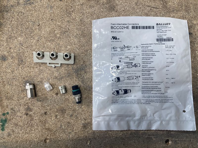
Étape 1 - Unpack the plug components
Inside the packet of the plug will be 5 components:
1- Metal outer shell
2- Numbered insert
3- m8 IDC connector
4- Individual 'white' grommet
5- Additional 3 grommetsMake sure you check that you have all of these parts before disposing of the packaging.
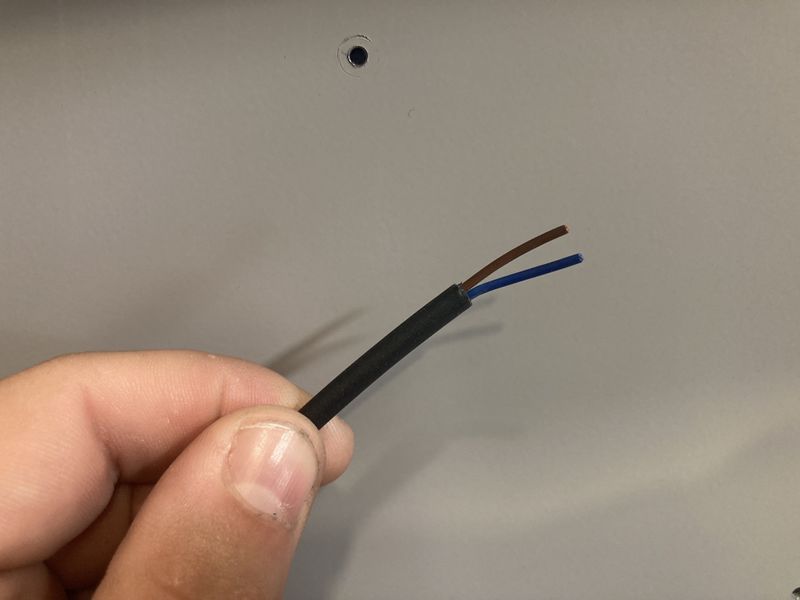
Étape 2 - Preparing the cable
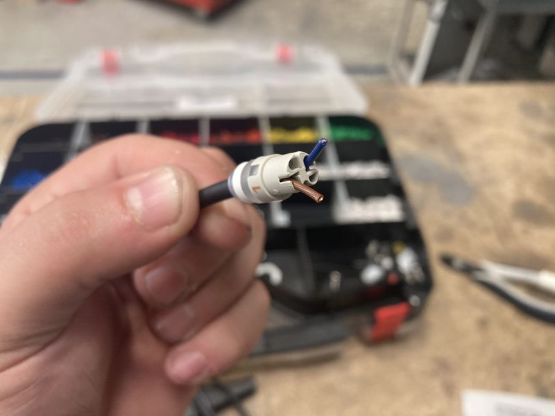
Once you have your cable run to its final location and cut to length, you will need to strip 20mm of the insulation back to expose the internal cores (The cable used in the example picture is a 2 core cable with 1 brown core and 1 blue core).
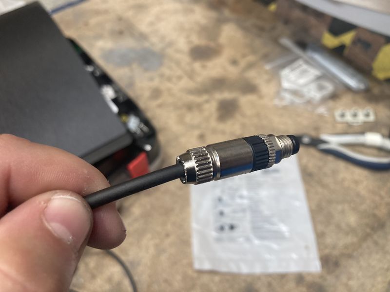
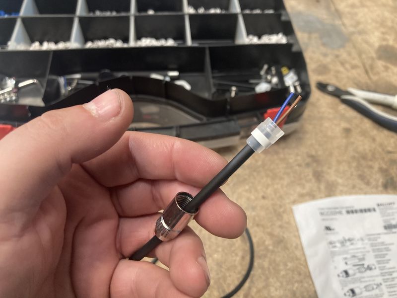
Étape 3 - Feed the outer shell over the cable
Make sure the tapared end of the shell goes over the cable first.
Étape 4 - Add the grommet to the cable
Depending on the cable being used, will determine which of the grommets will need to fitted. The 'white' grommet is the most common and is also the grommet used in the example pictures. Be aware that if a smaller cable is being used (ie; a reed switch) the smaller of the additional grommets should be used. All grommets are fitted in the same manner and orientation.
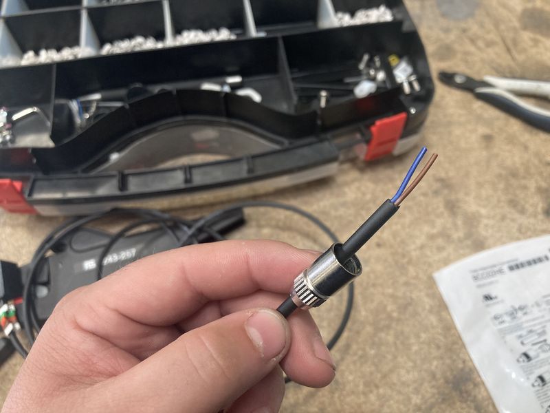
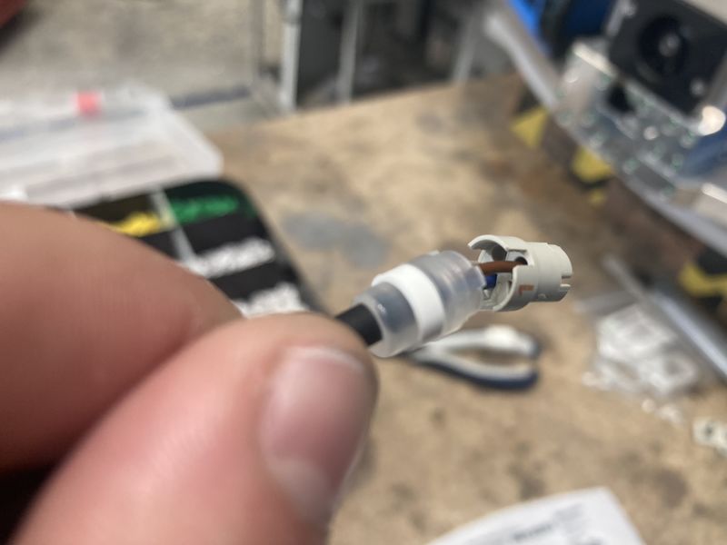
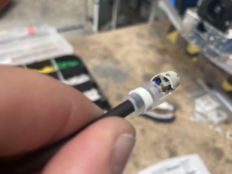
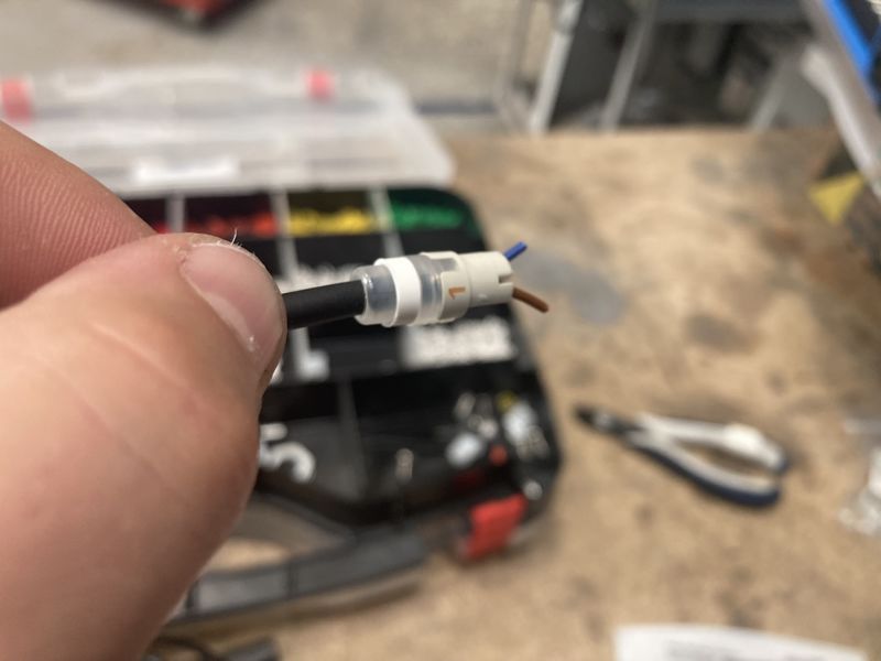
Étape 5 - Place cores through insert
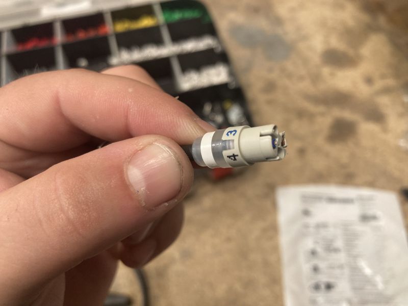
Place the wires through the insert. The insert has coloured numbers around the outside that correspond to a hole. The brown wire in this example goes into the hole next to the brown number 1. The blue wire goes into the hole next to the blue number 3. Nothing goes in the hole next to the black number 4. The insert needs to be pushed into the rubber grommet, ensuring the tabs on the insert and grommet line up. Once the insert has been pushed all the way into the grommet, the remaining wire that is pertruding from the end, needs to be cut flush.
Different cables and different components will change which colour cores core into each numbered hole. Always check the electrical drawings before this step. There is a file attached to this Dokit which has further information.
Étape 6 - Fitting the m8 IDC connector
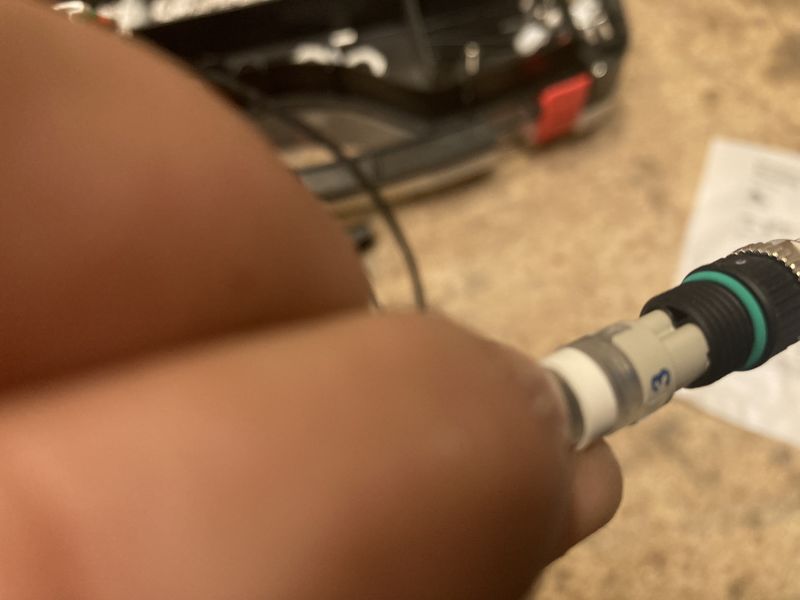
The insert has a rebated section which is designed to only allow the IDC connector to be pushed on in one orientation. To fit the IDC connector, line up the details and push the IDC connector firmly into the insert.
The IDC connector has contacts on the inside which will cut into the cores in the insert. This is how the electrical connection is made between the cores and the pins in the plug.
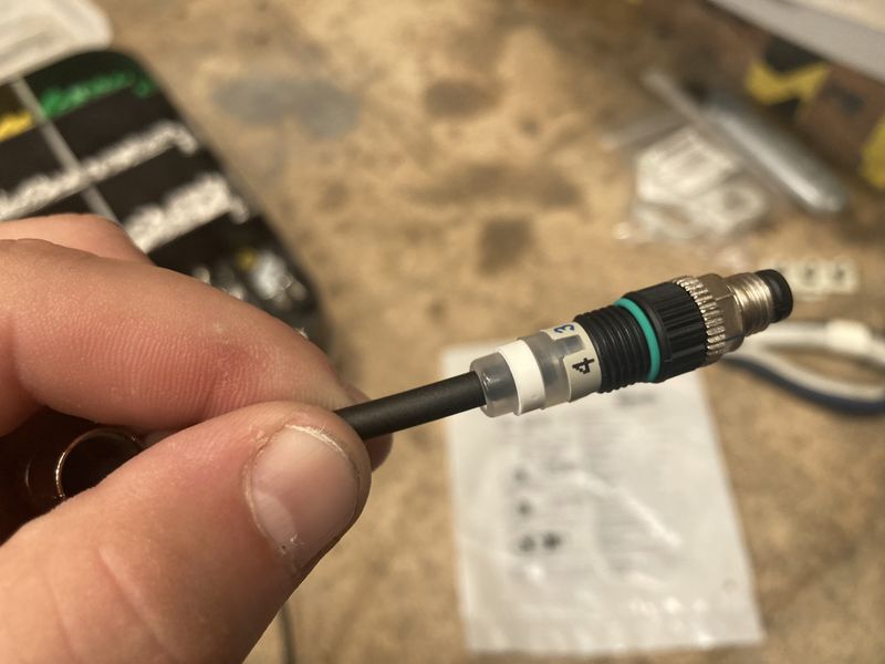
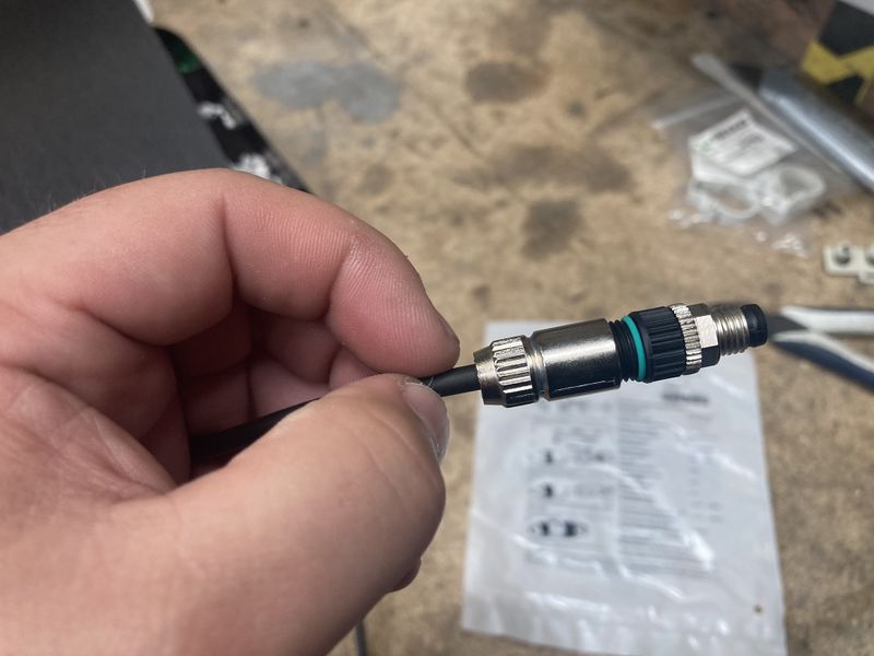
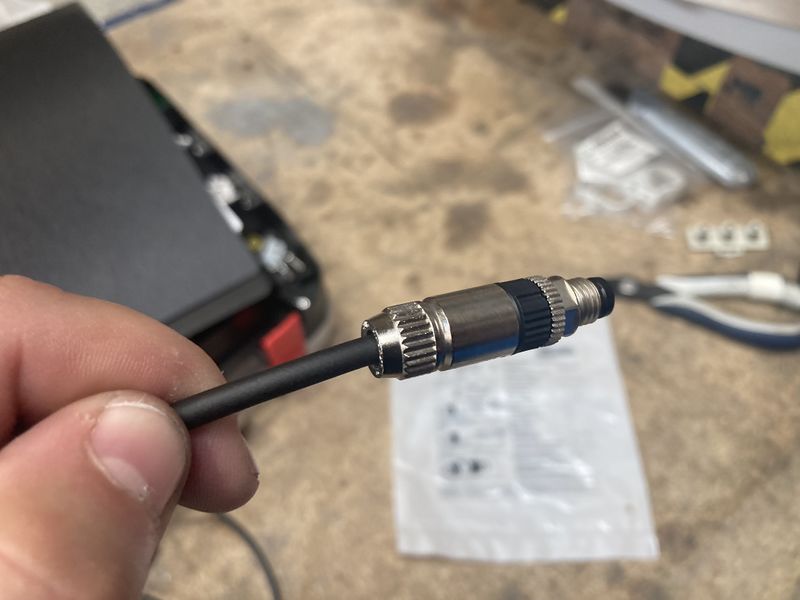
The bottom of the IDC connector has a thread to accept the metal shell. The metal shell should be hand tightened on the insert for as far as possible. Once it is finger tight, to sets of pliers will be needed to tighten the remained of the way.
You will see a green O ring on the IDC connector, this is a good guide to use to know when the shell is tight enough to the connector. When you are unable to see the green O ring is when the plug is correctly tight.
Draft
 Français
 English
 Deutsch
 Español
 Italiano
 Português