| [version en cours de rédaction] | [version en cours de rédaction] |
| Ligne 8 : | Ligne 8 : | ||
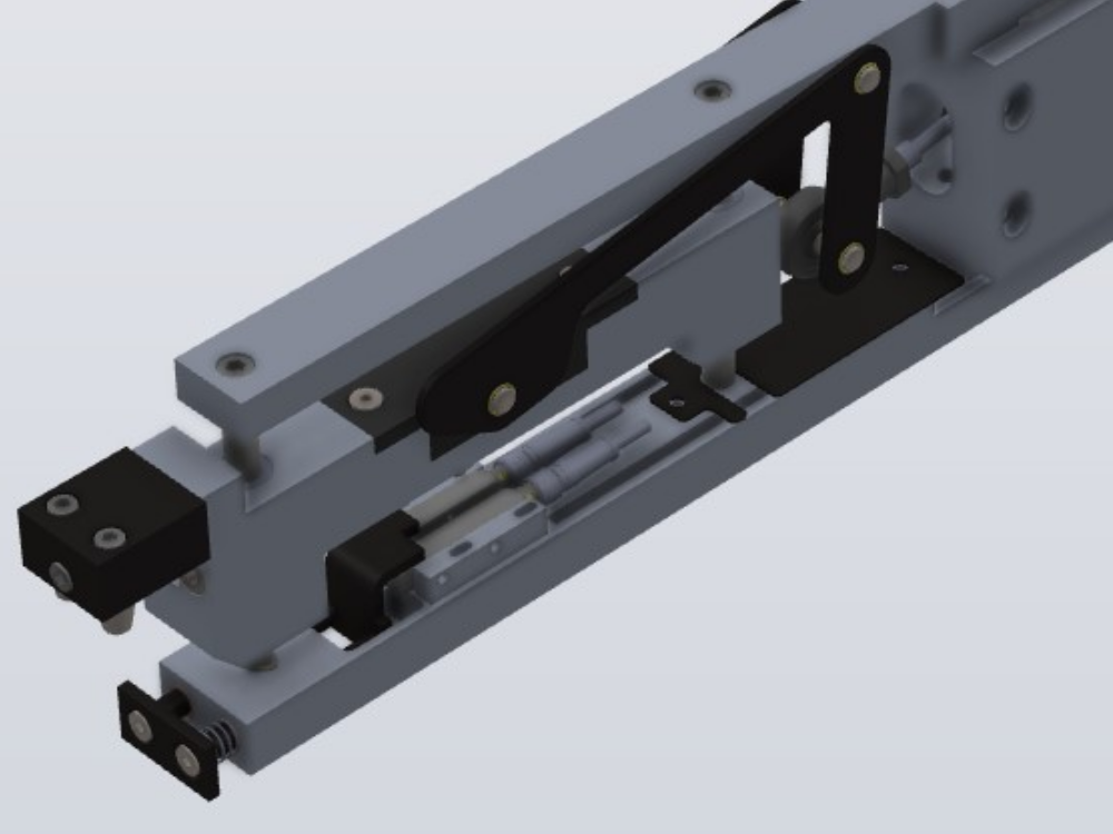
<translate>=Mechanical Setup= | <translate>=Mechanical Setup= | ||
This gripper design has two gripper switch inputs. This design was implemented to ensure the system can load a bar with an uneven or angled cut on the end. The sensors are activated by a long stroke on a spring, which has at least 10mm range of movement. | This gripper design has two gripper switch inputs. This design was implemented to ensure the system can load a bar with an uneven or angled cut on the end. The sensors are activated by a long stroke on a spring, which has at least 10mm range of movement. | ||
| + | |||
<br /> | <br /> | ||
{| class="wikitable" | {| class="wikitable" | ||
| Ligne 36 : | Ligne 37 : | ||
|- | |- | ||
|2 | |2 | ||
| − | |Wait for gripper max input | + | |Wait for gripper max input |
|(completely bottom out gripper) | |(completely bottom out gripper) | ||
|- | |- | ||
| Ligne 87 : | Ligne 88 : | ||
|Locks the gripper in its current position so it does not force the profile to "wheelie" | |Locks the gripper in its current position so it does not force the profile to "wheelie" | ||
|} | |} | ||
| − | + | ||
| + | = Gripper Lock = | ||
| + | {{Warning|...The cylinder locking devices on these cylinders are sprung loaded and locked on by default. They need to be piped to the opposite port of the valve so that the cylinder locks when the output is on}}</translate> | ||
{{PageLang | {{PageLang | ||
|Language=en | |Language=en | ||
Version du 15 juin 2023 à 17:11
How to set up a gripper on a Flowline Mk3 with a Toothed Gripper

Mechanical Setup
This gripper design has two gripper switch inputs. This design was implemented to ensure the system can load a bar with an uneven or angled cut on the end. The sensors are activated by a long stroke on a spring, which has at least 10mm range of movement.
| Sensor | Function |
|---|---|
| Grip Min | Senses that a profile is gripped in the jaws. It should be active just after the spring is depressed |
| Grip Max | Activates when profile hits "end stop" of gripper mechanism whn loading. This ensures a reliable datum point. It should be active when the spring is fully depressed |
Software Process on Machining Centre side
| Step | Action | Notes |
|---|---|---|
| 1 | Move to loadingpos plus 5mm | |
| 2 | Wait for gripper max input | (completely bottom out gripper) |
| 3 | Wait for gripper to be within 0.25mm of expected position and 100ms to pass (to allow system to settle) | |
| 4 | Clutch and material load motor off | |
| 5 | Move to loadingpos | Pushes profile back to |
| 6 | Clutch on | holds profile steady |
| 7 | Wait for trim Pause | |
| 8 | Move x axis to loadingpos+200mm | Clear of tooling head |
| 9 | Run datum hole routine | |
| 10 | Move to loadingpos | |
| 11 | Grip | |
| 12 | Wait for grip on time | |
| 13 | Check that grip min switch is active | Ensure the bar is gripped |
| 14 | Grip lock on | Locks the gripper in its current position so it does not force the profile to "wheelie" |
Gripper Lock
Draft
 Français
 English
 Deutsch
 Español
 Italiano
 Português