| [version en cours de rédaction] | [version en cours de rédaction] |
| Ligne 28 : | Ligne 28 : | ||
|Step_Title=<translate>Aligning the 100 mm set square with the Z section</translate> | |Step_Title=<translate>Aligning the 100 mm set square with the Z section</translate> | ||
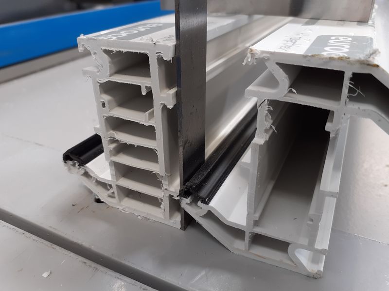
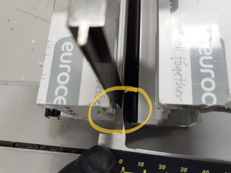
|Step_Content=<translate>Place the long face of the 100 mm set square vertically between the Z section and the straight edge as shown in the picture. Lay the short edge of the 150 mm set square along the top face of the Z section. This will support the 100 mm set square’s short edge and stop it falling over - as shown in the picture.</translate> | |Step_Content=<translate>Place the long face of the 100 mm set square vertically between the Z section and the straight edge as shown in the picture. Lay the short edge of the 150 mm set square along the top face of the Z section. This will support the 100 mm set square’s short edge and stop it falling over - as shown in the picture.</translate> | ||
| − | |Step_Picture_00= | + | |Step_Picture_00=Z_Transom_Width_Measurement_26C5E7BD-4823-4D53-B294-F0573E2ECBE0.jpeg |
|Step_Picture_01=Z_Transom_Width_Measurement_7E1924CC-6B69-4147-80BD-1B925EC1F3DA.jpeg | |Step_Picture_01=Z_Transom_Width_Measurement_7E1924CC-6B69-4147-80BD-1B925EC1F3DA.jpeg | ||
| − | |Step_Picture_02= | + | |Step_Picture_02=Z_Transom_Width_Measurement_CF375922-D2DE-43AB-8444-BE85D98FC3F1.jpeg |
}} | }} | ||
{{Tuto Step | {{Tuto Step | ||
Version du 11 août 2020 à 13:14
How to measure the width of a Z section profile
Introduction
- Pièces et outils
Pièces et outils
Étape 1 - Tools required
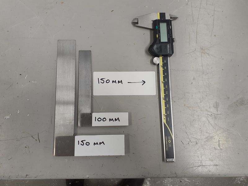
You will need a 150mm Vernier calliper, a 150mm set square and a 100mm set square.
Étape 2 - Materials required
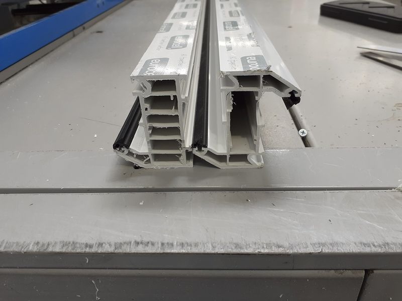
A straight faced piece of profile the same height as the Z section or taller or a piece of steel straight edge or the like; then lastly a Z section profile for measuring.
Étape 3 - Aligning the 100 mm set square with the Z section
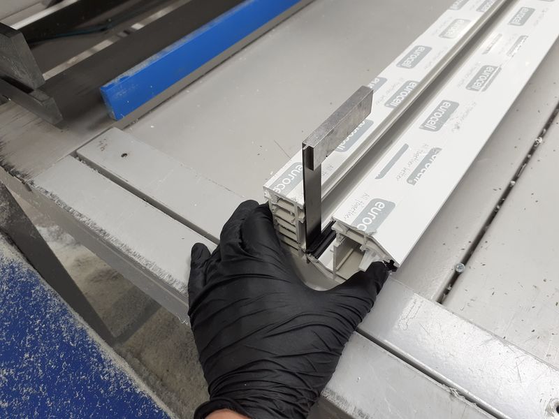
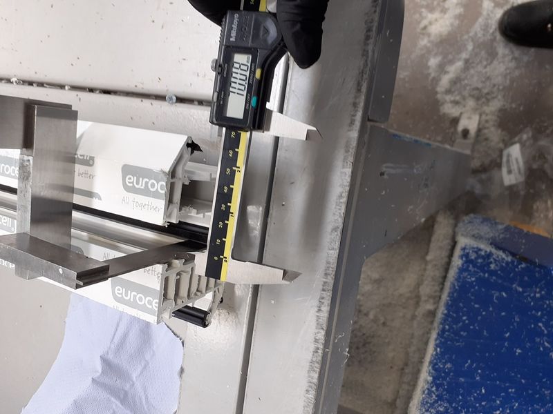
Place the long face of the 100 mm set square vertically between the Z section and the straight edge as shown in the picture. Lay the short edge of the 150 mm set square along the top face of the Z section. This will support the 100 mm set square’s short edge and stop it falling over - as shown in the picture.
Étape 4 - Measurement of section width
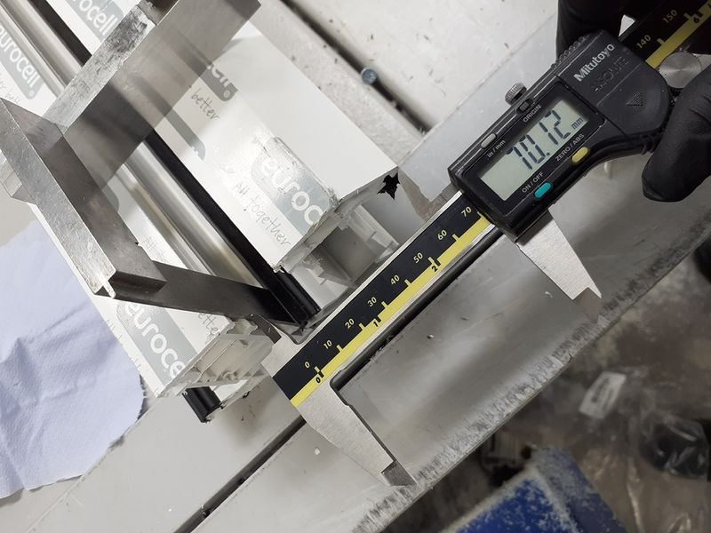
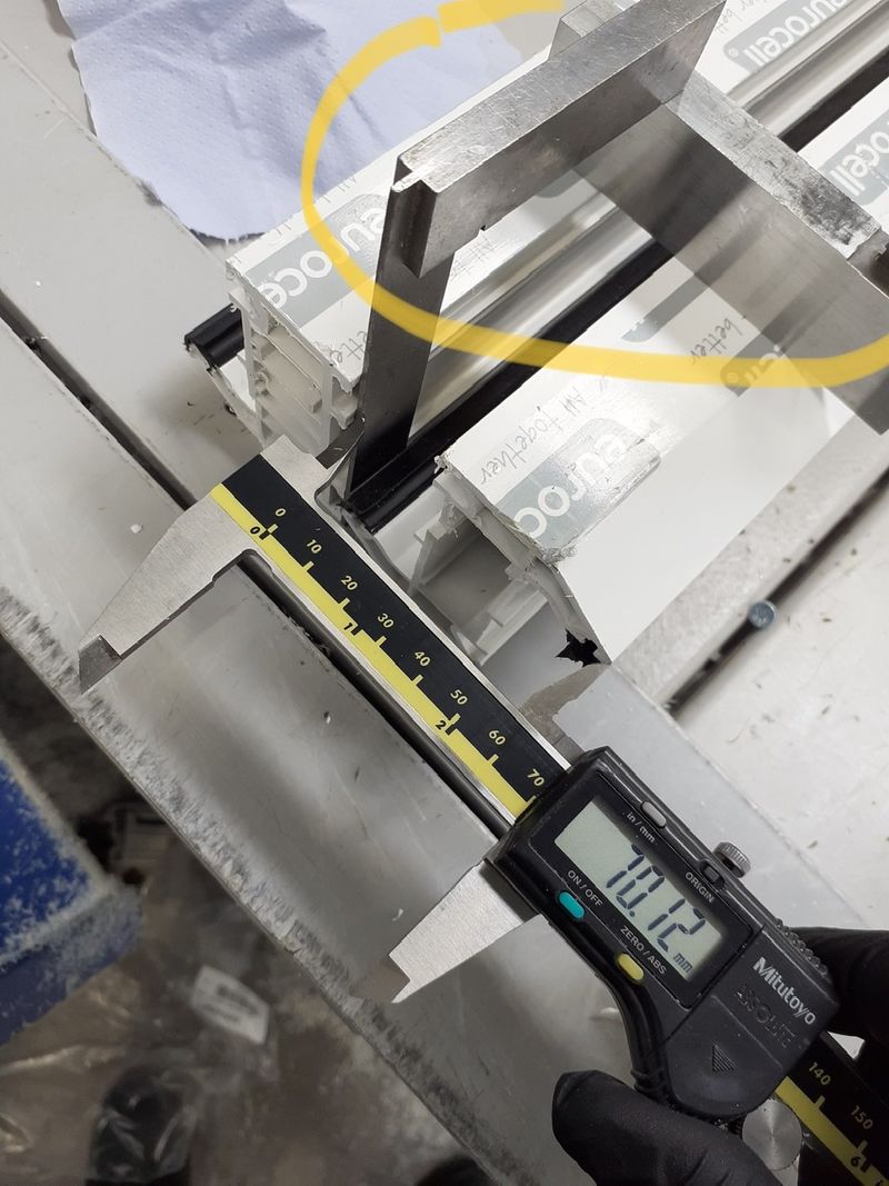
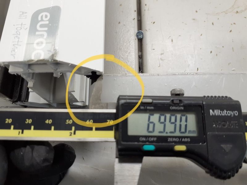
Using the 150 mm vernier calliper, place one end of the internal measurement faces against the 100 mm set square, then wind out the vernier scale until you reach the end of the top rebate leg of the Z section with the other vernier internal measurement face - as shown in the picture. This will give you an accurate measurement to 0.1mm of the section width to allow you to set up Y notching accurately on ZX5’s.
Draft
 Français
 English
 Deutsch
 Español
 Italiano
 Português