| [version en cours de rédaction] | [version en cours de rédaction] |
| (7 révisions intermédiaires par 2 utilisateurs non affichées) | |||
| Ligne 1 : | Ligne 1 : | ||
{{Tuto Details | {{Tuto Details | ||
|Main_Picture=WEG_Inverter_Setup_WEG_INV.jpg | |Main_Picture=WEG_Inverter_Setup_WEG_INV.jpg | ||
| − | |Main_Picture_annotation={"version":"2.4.6","objects":[{"type":"image","version":"2.4.6","originX":"left","originY":"top","left":- | + | |Main_Picture_annotation={"version":"2.4.6","objects":[{"type":"image","version":"2.4.6","originX":"left","originY":"top","left":-50,"top":-180,"width":480,"height":640,"fill":"rgb(0,0,0)","stroke":null,"strokeWidth":0,"strokeDashArray":null,"strokeLineCap":"butt","strokeDashOffset":0,"strokeLineJoin":"miter","strokeMiterLimit":4,"scaleX":1.51,"scaleY":1.51,"angle":0,"flipX":false,"flipY":false,"opacity":1,"shadow":null,"visible":true,"clipTo":null,"backgroundColor":"","fillRule":"nonzero","paintFirst":"fill","globalCompositeOperation":"source-over","transformMatrix":null,"skewX":0,"skewY":0,"crossOrigin":"","cropX":0,"cropY":0,"src":"https://stuga.dokit.app/images/7/72/WEG_Inverter_Setup_WEG_INV.jpg","filters":[]}],"height":450.54151624548734,"width":600} |
| − | |Description=<translate>How to set up the WEG inverters. used on the Transfer crank and Infeed modules | + | |Description=<translate>How to set up the WEG inverters. used on the Transfer crank and Infeed modules.</translate> |
|Categories=Operation, Production | |Categories=Operation, Production | ||
}} | }} | ||
| − | <translate>{{#annotatedImageLight:Fichier:WEG Inverter Setup WEG. | + | <translate>=History= |
| + | {| class="wikitable" | ||
| + | !Date | ||
| + | ! | ||
| + | !Photo | ||
| + | |- | ||
| + | |2021 | ||
| + | |Original Unit fitted due to supply chain issues with Eaton Motor Starters | ||
| + | |{{#annotatedImageLight:Fichier:WEG Inverter Setup WEG INV.jpg|0=300px|hash=8949fc49166f7e4d7b8b662cd08e1c91|jsondata={"version":"2.4.6","objects":[{"type":"image","version":"2.4.6","originX":"left","originY":"top","left":-106,"top":-178,"width":480,"height":640,"fill":"rgb(0,0,0)","stroke":null,"strokeWidth":0,"strokeDashArray":null,"strokeLineCap":"butt","strokeDashOffset":0,"strokeLineJoin":"miter","strokeMiterLimit":4,"scaleX":1.4,"scaleY":1.4,"angle":0,"flipX":false,"flipY":false,"opacity":1,"shadow":null,"visible":true,"clipTo":null,"backgroundColor":"","fillRule":"nonzero","paintFirst":"fill","globalCompositeOperation":"source-over","transformMatrix":null,"skewX":0,"skewY":0,"crossOrigin":"","cropX":0,"cropY":0,"src":"https://stuga.dokit.app/images/7/72/WEG_Inverter_Setup_WEG_INV.jpg","filters":[]}],"height":359.47136563876654,"width":480}|mediaClass=Image|type=frameless|align=center|src=/images/thumb/7/72/WEG_Inverter_Setup_WEG_INV.jpg/ia-8949fc49166f7e4d7b8b662cd08e1c91-px-WEG_Inverter_Setup_WEG_INV.jpg.png|href=./Fichier:WEG Inverter Setup WEG INV.jpg|resource=./Fichier:WEG Inverter Setup WEG INV.jpg|caption=|size=300px}} | ||
| + | |- | ||
| + | |2024 | ||
| + | |IO Module added to allow a fault signal to be fed back to control system | ||
| + | see [[ECN004 WEG Inverter Update - Fault Output]] | ||
| + | {{Warning|...Additional parameters needed when using IO block}}<br /> | ||
| + | |{{#annotatedImageLight:Fichier:WEG Inverter with IO.png|0=300px|hash=|jsondata=|mediaClass=Image|type=frameless|align=center|src=https://stuga.dokit.app/images/c/c1/WEG_Inverter_with_IO.png|href=./Fichier:WEG Inverter with IO.png|resource=./Fichier:WEG Inverter with IO.png|caption=|size=300px}} | ||
| + | |} | ||
| − | == | + | =Easy Start Guide= |
| + | {{#annotatedImageLight:Fichier:WEG Inverter Setup WEG.JPG|0=603px|hash=|jsondata=|mediaClass=Image|type=frameless|align=center|src=https://stuga.dokit.app/images/6/63/WEG_Inverter_Setup_WEG.JPG|href=./Fichier:WEG Inverter Setup WEG.JPG|resource=./Fichier:WEG Inverter Setup WEG.JPG|caption=|size=603px}} | ||
| − | == | + | = Parameters = |
| + | {| class="wikitable" | ||
| + | |+Parameter Settings | ||
| + | !Number | ||
| + | !Setting | ||
| + | !Function | ||
| + | !Notes | ||
| + | |- | ||
| + | |P100 | ||
| + | | | ||
| + | |Accel Time | ||
| + | |See Below | ||
| + | |- | ||
| + | |P101 | ||
| + | | | ||
| + | |Decel Time | ||
| + | |See Below | ||
| + | |- | ||
| + | |P133 | ||
| + | |50 | ||
| + | |Min Frequency Ref | ||
| + | | | ||
| + | |- | ||
| + | |P134 | ||
| + | |50 | ||
| + | |Max Frequency Ref | ||
| + | | | ||
| + | |- | ||
| + | |P271 | ||
| + | |1 | ||
| + | |Set DIx to 24v DC | ||
| + | | | ||
| + | |- | ||
| + | |P220 | ||
| + | |1 | ||
| + | |Remote Selection | ||
| + | | | ||
| + | |- | ||
| + | |P226 | ||
| + | |4 | ||
| + | |Remote Rotate Selection | ||
| + | | | ||
| + | |- | ||
| + | |P227 | ||
| + | |1 | ||
| + | |Remote Run Selection | ||
| + | | | ||
| + | |- | ||
| + | |P263 | ||
| + | |4 | ||
| + | |DI1 Function (FWD) | ||
| + | | | ||
| + | |- | ||
| + | |P264 | ||
| + | |5 | ||
| + | |DI2 Function (REV) | ||
| + | | | ||
| + | |- | ||
| + | |P265 | ||
| + | |20 | ||
| + | |DI3 Function (RESET) | ||
| + | | rowspan="3" |Only Used when IO Module is fitted to front of unit | ||
| + | |- | ||
| + | |P266 | ||
| + | |40 | ||
| + | |DI4 Function (ESTOP) | ||
| + | |- | ||
| + | |P275 | ||
| + | |13 | ||
| + | |DO1 Function (FAULT) | ||
| + | |} | ||
| + | <br /> | ||
| + | {| class="wikitable" | ||
| + | |+Accel and Decel (P100 & P101) Values | ||
| + | !Machine Type | ||
| + | !Inverter Location | ||
| + | (Module Panel) | ||
| + | !Motor Location | ||
| + | (Module) | ||
| + | !Motor | ||
| + | !P100 | ||
| + | !P101 | ||
| + | |- | ||
| + | | rowspan="5" |ZX5 | ||
| + | |A | ||
| + | |A | ||
| + | |Infeed Conveyor | ||
| + | |0.1 | ||
| + | |0.1 | ||
| + | |- | ||
| + | |A | ||
| + | |A | ||
| + | |Infeed Wheel | ||
| + | |0.1 | ||
| + | |0.1 | ||
| + | |- | ||
| + | |B | ||
| + | |C | ||
| + | |Crank | ||
| + | |0.5 | ||
| + | |0.1 | ||
| + | |- | ||
| + | |B | ||
| + | |D | ||
| + | |Crank | ||
| + | |1.0 | ||
| + | |0.2 | ||
| + | |- | ||
| + | |B | ||
| + | |E | ||
| + | |Crank | ||
| + | |0.5 | ||
| + | |0.1 | ||
| + | |- | ||
| + | |Autoflow Mk4 | ||
| + | |B | ||
| + | |A | ||
| + | |Infeed conveyor | ||
| + | |0.5 | ||
| + | |0.5 | ||
| + | |} | ||
| − | = | + | =Further Information= |
| − | + | [https://static.weg.net/medias/downloadcenter/hf5/h40/WEG-cfw100-programming-manual-10002853582-2.3x-manual-english.pdf Programming Manual] | |
| + | |||
| + | <br /></translate> | ||
{{PageLang | {{PageLang | ||
|Language=en | |Language=en | ||
| Ligne 20 : | Ligne 158 : | ||
{{AddComments}} | {{AddComments}} | ||
{{Tuto Status | {{Tuto Status | ||
| − | |Complete= | + | |Complete=Published |
}} | }} | ||
Version du 28 octobre 2024 à 11:58
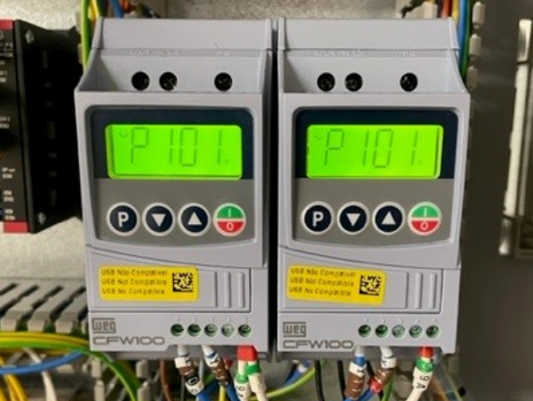
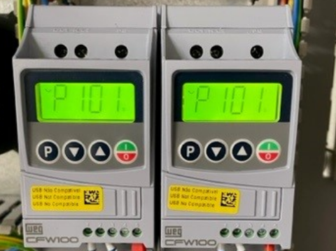
How to set up the WEG inverters. used on the Transfer crank and Infeed modules.
History
| Date | Photo | |
|---|---|---|
| 2021 | Original Unit fitted due to supply chain issues with Eaton Motor Starters | |
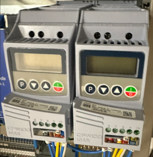
| 2024 | IO Module added to allow a fault signal to be fed back to control system
see ECN004 WEG Inverter Update - Fault Output |
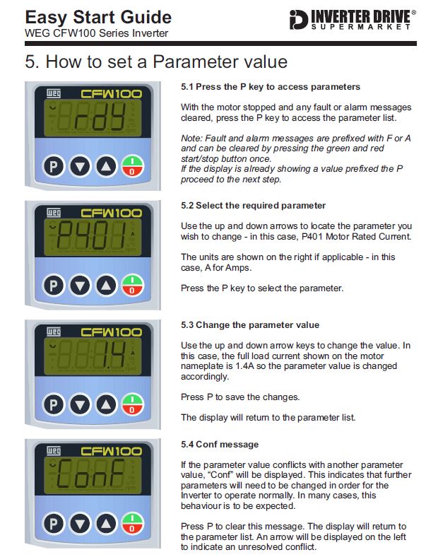
Easy Start Guide
Parameters
| Number | Setting | Function | Notes |
|---|---|---|---|
| P100 | Accel Time | See Below | |
| P101 | Decel Time | See Below | |
| P133 | 50 | Min Frequency Ref | |
| P134 | 50 | Max Frequency Ref | |
| P271 | 1 | Set DIx to 24v DC | |
| P220 | 1 | Remote Selection | |
| P226 | 4 | Remote Rotate Selection | |
| P227 | 1 | Remote Run Selection | |
| P263 | 4 | DI1 Function (FWD) | |
| P264 | 5 | DI2 Function (REV) | |
| P265 | 20 | DI3 Function (RESET) | Only Used when IO Module is fitted to front of unit |
| P266 | 40 | DI4 Function (ESTOP) | |
| P275 | 13 | DO1 Function (FAULT) |
| Machine Type | Inverter Location
(Module Panel) |
Motor Location
(Module) |
Motor | P100 | P101 |
|---|---|---|---|---|---|
| ZX5 | A | A | Infeed Conveyor | 0.1 | 0.1 |
| A | A | Infeed Wheel | 0.1 | 0.1 | |
| B | C | Crank | 0.5 | 0.1 | |
| B | D | Crank | 1.0 | 0.2 | |
| B | E | Crank | 0.5 | 0.1 | |
| Autoflow Mk4 | B | A | Infeed conveyor | 0.5 | 0.5 |
Further Information
Published


 Français
 English
 Deutsch
 Español
 Italiano
 Português