Details for alignment of module G to F inclusive of additional safety tray fitting
Auteur  Gareth Green | Dernière modification 11/09/2025 par Gareth Green en cours de rédaction ⧼frevu-button-review-label⧽
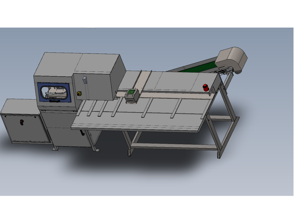
Details for alignment of module G to F inclusive of additional safety tray fitting
ZX5_Production_R0000548E_Module_G_to_R0015040_Module_F_alignment_Screenshot_2023-12-21_081410.png
en none 0 Draft
Vous avez entré un nom de page invalide, avec un ou plusieurs caractères suivants :
< > @ ~ : * € £ ` + = / \ | [ ] { } ; ? #
 Français
 English
 Deutsch
 Español
 Italiano
 Português