Setting up external router for customer network isolation
Technical Bulletin
| TB Number: | 323 |
| Originator: | Gareth Green |
| Machine: | All |
| Date: | 15/09/16 |
| Circulate to: | Service; Design;
DO NOT FORWARD TO CUSTOMERS WITHOUT PERMISSION FROM GMG |
| Title: | Stuga On-Site Private Networking “Net-116” |
Overview
All customer internal networks are different, and Stuga Service have been having increasing problems with issues related to areas beyond our control. Problems include:
· Loss of network connection to printer
· Cannot connect to Drive D from MH to Saw on switch-on
· Loosing batch directory connection
· Crashing during program running
Root causes can be
· IP address conflicts with iPhones and other random device
· Security protocols on customer network
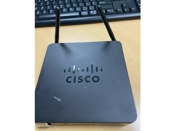
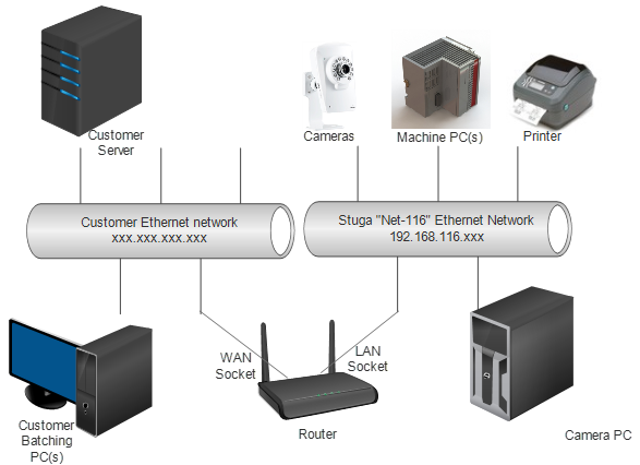
A solution to this is to put the Stuga devices in their own “ring-fenced” network, with their own range of IP addresses that the customer devices cannot use. To enable this, the Stuga network needs its own router (a box that generates its own IP address range), to act as bridge between customer network and Stuga network. This enables us to permanently fix the same IP addresses on every machine we produce. Another benefit is that a WiFi router can give our Staff instant internet access with the same password all the time. A pilot scheme has been launched on Z049 for Radley, despatched 15/09/16.
The new Router forms a bridge between the customer’s network and ours. This means the IP range on the customer side can be anything, yet on the Stuga side, the network range and IP addresses can be fixed tin the range 192.168.116.1 to 192.168.116.255.
The following standard policy has been designed for IP addressing on the Stuga network. This standard allows multiple machines on the same network with up to 20 IP addresses for each machine.
192.168.116.axn
X is assigned as 1 for one machine, 2 for second machine, 3 for 3rd, etc. This is for multiple Stuga machines on the same site. Within this, the final digit is fixed for the device type on each machine:
| IP Address | Device | Example for Single Machine |
| 192.168.116.001 | Router | |
| 192.168.116.0x1 | Camera PC | 192.168.116.11 |
| 192.168.116.0x2 | Main Machine PC | 192.168.116.12 |
| 192.168.116.0x3 | Second Machine PC (eg Saw) | 192.168.116.13 |
| 192.168.116.0x4 | Printer | 192.168.116.14 |
| 192.168.116.0x5 | Inverter / Brainbox device | 192.168.116.15 |
| 192.168.116.0x6 to
192.168.116.0x9 |
Cameras | 192.168.116.16 to
192.168.116.19 |
| 192.168.116.1x0 to 192.168.116.1x9 | Future expansion (e.g. more cameras) | 192.168.116.110 |
Note: Leading Zeros are NOT required for most devices, only add it to the setup if the device needs it
Router Set up schedule for Cisco RV215W
This is done at Stuga before sending the router to site
Goals:
· Create a private Stuga network with ip range 192.168.116.xxx.
· Set up router as a bridge between customer network and Stuga network
· Create a secure wireless access point for Stuga Engineer use ONLY
· Create a fixed, standard IP range for the Stuga machines
| 1. | Find current DNS address of customer network (cmd-> ipconfig /all. DNS Server address should be displayed) |
| 2. | Connect Router in between customer network and machine(s) |
| 3. | Ensure a PC on Stuga side is set to DHCP to get an IP address assigned |
| 4. | Using this PC, connect to the Router web page - Open Internet Explorer, http://192.168.1.1 |
| 5. | Username cisco, password cisco |
| 6. | On wizard, click next to detect network, this will detect customer network |
| 7. | Keep existing WAN connection setting (should be Dynamic IP Address) |
| 8. | Enter time zone - GMT (England) |
| 9. | Use Default MAC Address |
| 10. | Enter new password: Stuga001 |
| 11. | Enter Network Name: StugaWiFi |
| 12. | Choose "Better Security" and enter password: S.T.U.G.A.0.0.1 |
| 13. | Click Yes on WPS warning |
| 14. | Log back in to router |
| 15. | Navigate to Networking->LAN->LAN configuration |
| 16. | Change Local IP Address to 192.168.116.1 |
| 17. | Click Save, then Yes to restart |
| 18. | Log back in to router on http://192.168.116 |
| 19. | Set up each Stuga device IP addresses as per standard policy (PCs, printers, cameras, etc)
Note: Leading Zeros are NOT required for most devices, only add it to the setup if the device needs it · Default Gateway should be 192.169.116.1 · DNS should be the original DNS setting from Step 1 · Camera recording NAS settings will need to be changed |
| 20. | On Stuga Windows 7, 8 or 10 PCs, make the new network a private network.
a. Open Explorer and click on Network. b. A yellow bar should appear "Network discover and...". c. Click on it, Then click "Turn on network and file sharing". d. Then click "No, make the network that I am connected to a Private Network |
| 21. | Remap any mapped drives:
· D: drive · Batches folder on customer PC |
| 22. | Ensure Teamviewer connection works (This is usually an incorrect DNS address) |
Reversing The Changes
If the router needs to be removed or overidden:
- Replace the Cisco Router with and other standard switch
- Reverse the changes in Step 19. The IP addresses are best fixed to spare ones on the customer's network. The Default Gateway will be the main customer Default Gateway
Draft


 Français
 English
 Deutsch
 Español
 Italiano
 Português