User Guide for Stuga Router

Sommaire
- 1 1. What is the Router?
- 2 2. Router Functions
- 3 3. Getting Started
- 4 4. Program Storage System
- 5 5. Troubleshooting
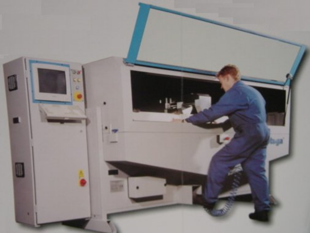
1. What is the Router?
The STU440 is a machine tool capable of machining on any one of 3 faces of an extrusion. The Router can be used to prepare both aluminium and PVC-u extrusions.
The cutting head can be programmed to move through three dimensions to cut or drill any arrangement of holes or slots.
A 3-spindle head is moved along any one of 3 axes of movement - known as the X axis, the Y axis and the Z axis. Using this movement, shapes and holes can be routed out of the extrusion.
The machine is programmed by the operator using simple positioning commands and output control commands.
1.1. Sections of the Router
The Router comprises the following main components:
· Routing cabinet
· Control Panel
· Carriage and Cutting Head
· Material Clamps.
1.1.1. Routing Cabinet
This is the main component of the Router and includes all the mechanical components.

1.1.2. Control Panel
This panel includes all the controls as shown below. The operator normally uses the stored programs of movement commands, which are stored on the internal hard disk drive of the PC-compatible computer system.

1.1.3. Carriage and Cutting Head
This is contained within the main cabinet and features a multi-spindle overarm headstock of up to three 90 degree opposed cutter spindles. By using standard 8mm cutters, machining can be carried out on any of three faces along the entire length of an extruded section.

1.1.4. Material Clamps
Secure clamping is provided by clamp block assemblies. The upward stroke of the clamp block assemblies ensures an accurate datum at the top profile blocks.
The clamping assemblies are pneumatic powered and actuated by a foot valve.

1.2. Where are the Controls?
The controls for the Router are located in the Control Cabinet to the left of the main Routing module. They comprise:
· Start and Stop buttons
· Switch On and Off buttons
· Inch buttons
· Emergency Stop button
· Computer screen and keyboard.
2. Router Functions
The STU440 Router is used to drill holes and cut slots in PVc-u and aluminium extrusions of window industry standard profiles. The cutting heads can be programmed to move through three dimensions to cut or drill any combination of slots or holes.
Using latest PC compatible computer system, the Router runs a stored program of movement commands. These programs are stored on a hard disk drive inside the machine.
2.1. Special Features
The Stuga SU440 Router has the following features:
· Fully automatic machining cycle
· High volume accurate production
· Instant changeover of routing routines
· Uses standard 8mm cutters.
2.2. Safety Features
2.2.1. Danger Points
The danger points on the machine have been defined as follows:
1. The electrical cabinet.
2. The working area where the three drills approach the work from the back and the router approaches from the bottom.
3. Inside the guarding of the machine if the door is open.
2.2.2. Design Features
To prevent the user sustaining accidental injury using this machine, there are a number of safety features built into the design.
· Electrical safety interlock on the cabinet door. (Danger point 1).
· Safety interlock on the front and top access doors. The operations will not run if either guard is opened. (Danger point 3)
· Material loaded sensor. This sensor will not allow the machining operations to start until material is loaded. This protects the user from danger point 2.
· Adjustable guard / support. When adjusted correctly to the profile width plus 2 mm clearance, it should be impossible for the operator to get his fingers near danger point 2.
Emergency stop button will remove power from the two motors and withdraw the pneumatic actuators when depressed. The button has to be pulled in order to reset the emergency stop condition.
3. Getting Started
3.1. Introduction
The Router is controlled from the main control panel to the left side of the machine. The panel houses the main ON and OFF buttons together with the controls to run the machine under normal conditions.
3.2. Switch On Machine
Power is switched on with the isolator switch at the side of the machine.
| Step | Action |
| 1. | To start the Router press the ON button at the top of the control panel. The red indicator lamp on the control panel will illuminate when the machine is ready to operate. Ensure an adequate air supply is available. |
| 2. | The Router will take about 1 minute to initialise. If any of the guard doors are open, or the air pressure is not high enough, a message will be displayed telling the operator the problem. |
| 3. | The machine will not operate any further until the problems are rectified. The machine is ready when the main start screen below is displayed. |
NOTE: If when you start the machine there is a piece of material in the clamp area, then you must use the Inch buttons to inch the Z-axis before raising the Z-axis.
3.3. Loading Material
Before machining, ensure there is no obstruction of particles on the working surface before clamping the workpiece.
| Step | Action |
| 1. | Open the self-centring mechanism by sliding the handle outwards. |
| 2. | Load the material into the machine. |
| 3. | Centralise the bar by moving the centralising handle fully inwards, ensuring there are no obstructions.
The machining operations will not start until the workpiece is loaded correctly. |
| 4. | Press the Start button to begin the machining cycle |
| 5. | Remove the material by opening the centralising mechanism. |
3.4. Menu Organisation
Pressing ENTER key displays the main Router menu as below:

This menu enables you to carry out the following actions:
F1 Run ‘.stu’ programs
F2 Run ‘.sec’ programs with positions
F3 Edit programs
F4 Create/delete Directories and Backup Facilities for hard disk
F5 Exit program
F6 Extended Options
NOTE: Pressing Esc will always return you to the main menu from wherever you are in the program.
NOTE: All functions are accessed by passing through the main menu, that is, to jump from running '.stu' programs to editing, you must go back through the main menu.
3.5. Single Program Mode
<F1> from the main menu puts the machine in single program mode. This mode allows you to run single programs with a '.stu' extension.
When loading a program, you will first be asked to specify a profile suite, then select a program, and finally enter the bar length.

3.5.1.1. Procedure
| Step | Action |
| 6. | Select profile suite from the Suite list displayed where the cursor is showing. Press ENTER to confirm.
The screen now displays the list of programs. |
| 7. | Select the program by moving the cursor with the up and down keys.
Press ENTER to confirm, and the following display appears: |
| 8. | Enter the New length of the material in mms, and press ENTER to confirm. The following new message is displayed
 |
| 9. | Load the bar into the Router and set up the 2 stage clamps. |
| 10. | Press ENTER to run the program, the program runs and the display brings up the Single Program Main Menu:
The Spindles and Clamps box shows you which spindles and clamps are being used. |
| 11. | Press ENTER to run the sequence again. |
| 12. | Press a key on the keyboard to take you to the Single Program Main Menu.
Here, you can load a different program, change the bar length of the current program, or return to the main menu. |
3.6. Emergency Stop and Reset
The Stuga router has an emergency stop safety relay that disables all functions of the machine under fault / emergency conditions. These conditions are:
● Emergency Stop Pressed
● Guard Door Open
● Carriage overrides limit of movement.
Under any of these conditions, the relay is tripped and the lamp on the ES Reset button is illuminated.
In each fault case, the fault must be cleared (ie reset emergency stop buttons, close guard door, wind x axis off limit). The operator then presses the ES Reset button to reset the relay.
3.7. Stop Program
In order to stop the program running, you have to press any one of the Emergency Stop buttons.
3.8. Inch Buttons
The inch buttons are used to clear the cutter from the bar following an emergency stop occurring.
3.8.1. Datum Sequence
The sequence of setting the datums is Z, Y and then X.
3.9. Repeat Program
To run the same program again for another piece of material follow this procedure.
| Step | Action |
| 1. | Load the new bar into the Router and clamp the bar. |
| 2. | Press START and the program will run again. A confirmation message is again displayed. |
3.10. Change Length and Program
You can change the length of any new bars to be used on the same program from the Single Program Main Menu as follows:

3.10.1. Change Length
To change the length of the bars being used in the same program follow this procedure.
| Step | Action |
| 1. | Select <F1> to display the Change length box. |
| 2. | Enter the new length in mms and press START.
The new length appears in the Program Name box and a message is displayed to press START. |
| 3. | Load the new length bar into the Router and set up the 2 stage clamps. |
| 4. | Press ENTER and the program will run again for the new length of bar. A confirmation message is again displayed. |
3.10.2. Change Program
To change the program completely, follow this procedure.
| Step | Action |
| 1. | Select <F2> to display the Program Suite screen.
Move the cursor to select the new program and press RETURN to confirm. |
| 2. | Select new program and press ENTER to confirm. |
| 3. | Enter the new length in mms and press ENTER.
The new length appears in the Program Name box and a message is displayed to press Start. |
| 4. | Load the bar into the Router and clamp the bar. |
| 5. | Press ENTER and the new program will run again for the bar. A confirmation message is again displayed. |
4. Program Storage System
4.1. Profile Directories
4.1.1. Program and Subroutine Organisation
All programs ('.stu') and subroutines ('.sec'), must be assigned to a particular profile suite. The control environment is set up so that the user must create a list of profile suites. When a program or subroutine is created, it must be saved to a particular profile suite. The user is prompted at every stage to choose a profile suite from the list created.
The diagram below demonstrates this organisation. Each suite can be thought of as an area on the disc dedicated to programs and subroutines operating on that particular suite.

4.2. Installing and Deleting Profile Directories or Suites
Profile directories or suites are added using the F6 - Extended Options on the Main Menu.
4.2.1. Create Profile Directory
| Step | Action |
| 1. | Press <F6> to enter the Extended Options. This displays the following menu |
| 2. | Select <F1> to create a Profile Directory/Suite, and the following dialogue box is displayed,
NOTE: Do not enter a space in the profile name. The computer automatically puts a '.PRF' extension on the end in order to distinguish it on the disk. The profile is then installed on the disk. |
| 3. | Repeat this procedure for all your profile suites. |
| 4. | If a mistake is made, or a suite is not required any more, it can be deleted from the disc with the <F2> key.
CAUTION: Care should be exercised in deleting profile suites, however, since all the programs and subroutines will be irretrievably lost. |
4.3. Backing up and Restoring Data
Since computer systems are not completely infallible, it is a very sensible idea to keep a backup of all your programs and subroutines on 3.5" disc. This is carried out from the Extended Options menu using F3 – Backup Hard Disc.
This option <F3> allows easy backup of all programs and subroutines.
| Step | Action |
| 1. | Select <F3> and the following screen is displayed,
Use 1 floppy disk for each profile directory/suite. |
| 2. | Select the profile suite from the list and press ENTER. The following progress box is displayed to inform you the data is being copied.
|
4.4. Transfer Profiles From Floppy Disk
Restoring data from your 3.5" disk is just as simple, use the F4 Option and choose the profile as before.
| Step | Action |
| 1. | Select <F4> and the following menu is displayed:
This menu provides you with 3 different methods of transferring files. |
| 2. | Press <F1> to transfer only the .stu programs, and the next screen is displayed: |
| 3. | Select the transfer destination from the Suite list, and press ENTER. The next screen is displayed: |
| 4. | Select the file using the cursor keys and press ENTER. The data is then transferred to the hard disk. |
| 5. | Repeat step 4 for all the files you wish to transfer to the hard disk. |
| 6. | When you have completed the transfer, press Esc to return to the Transfer Menu, as shown in step 1. |
| 7. | Press <F5> to return to the Extended Options Menu. |
To transfer other file types, you need to use the other options on the menu. Repeat steps 2 to 4 for options F2 and F3.
4.5. Access Code
The Stuga Router has an Access Code to prevent unauthorised users from changing certain of the programs and setup of the machine. The Access Code protects the Editor and Extended Options items of the Main Menu.
As an operator you do not have security rights to change the code, this has to be done by your manager.
NOTE: All editing functions are described in the Router Programming Manual.
5. Troubleshooting
5.1. Emergency Stop/Guard Opened/Air Pressure Drop
If one of the above conditions happens, the machine will stop. It will not start again until that condition has been corrected. i.e. Emergency stop buttons should be reset, guards must be shut, and/or air pressure must be returned to normal.
There are two different procedures to follow:
a) Continue from where the stop condition occurred.
b) Reset and return to datum.
5.1.1. Continue
| Step | Action |
| 1. | Press the START button. The machine will continue from the stop point. |
5.1.2. Reset
| Step | Action |
| 1. | Press the STOP button.
This has the effect of aborting machining on the current bar and resetting the machine ready for the next bar. Press START to reset the Emergency Stop circuit. |
| 2. | Press START to return the pusher to its zero position. |
| 3. | Remove any material left on the Infeed side of the Router. |
| 4. | Press START again to begin machining on the next bar. |
5.2. Poor Cutting
This is normally due to the cutter being blunt and/or the cutting speed being too fast.
In the first case you must change the cutters, which is described in the Maintenance and Technical Manuals.
In the second case you must adjust the cutting speed, which is described in the Programming Manual, under Linear Movements and Speeds.
5.3. General Faults
| Symptom | Fault | ||
| Indicator lamp is off | Mains not connected to machine. Check main fuse.
Fuse F3 has blown. |
||
| Indicator lamp is on, Machine will not start | Material not loaded in machine.
Material loaded switch (X1) faulty. Emergency Stop depressed. Guards not closed. Mains neutral not connected. Fuse F2 or F3 blown. |
||
| Drill operation carried out but not routing | Drills Home switch (X4) faulty. | ||
| Router spindle not completing slot properly | Adjustable time delay on PLC is not set long enough. The time delay allowed for the routing action is adjustable on the PLC unit inside the control box.
Lifting the small cover flap on the right of the unit exposes a socket and a small potentiometer with a cross head. Using a small screwdriver, turn the potentiometer clockwise to increase the time and anticlockwise to decrease. |
||
Draft
 Français
 English
 Deutsch
 Español
 Italiano
 Português