Instructions to mount cut guard

Difficulté
Moyen
Durée
5 heure(s)
Introduction
Tools Required
Standard hex key set
Standard HSS drill set
Standard tap set
Cutting disc
Parts Required
C0001275 Printer: ZD421 Direct Thermal (Not Incl. C0001276 P&P)
C0001276 Peel & Present for ZD421 Printer
D0016333 Bruehl Fence panel 1700 x 800 x 2
D0016334 Bruehl Fence panel 650 x 800 x 2
H0005178 Safety Table Extension x 1
M0000033 Frame End Cap 50 x 50 x 1
M0001207 Bruehl Fence Clip x 14
P0000069 Tube to tube fitting 6mm x 1
R0015290 Saw Outfeed Bench Assemble Top guard x 1
Étape 1 - Unless otherwise stated
Use loctite 243 on all fasteners
Use Loctite 572 on all threaded pneumatic connections
Pen mark all bolts to show finalised

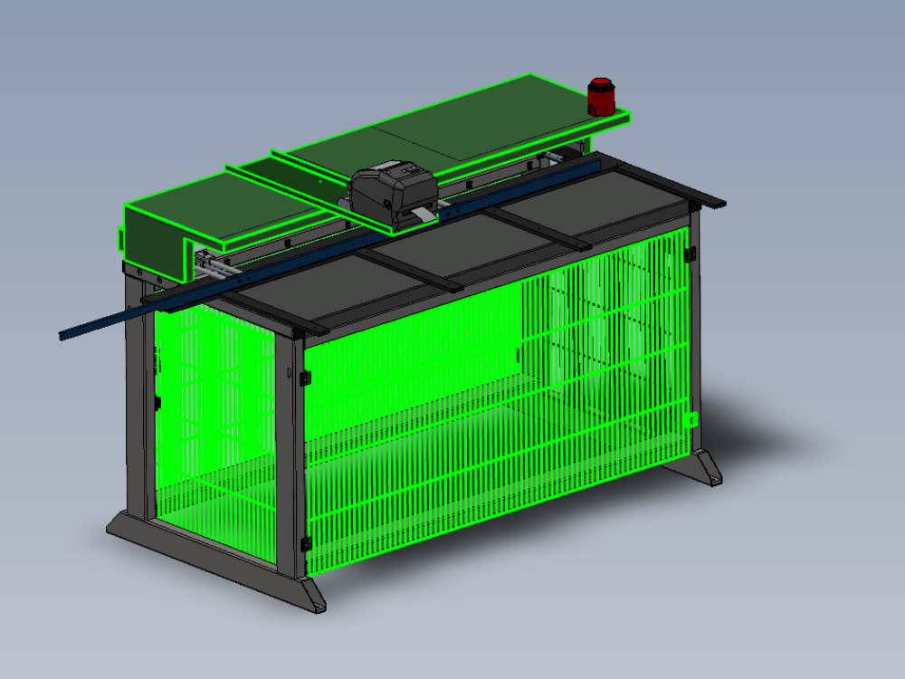
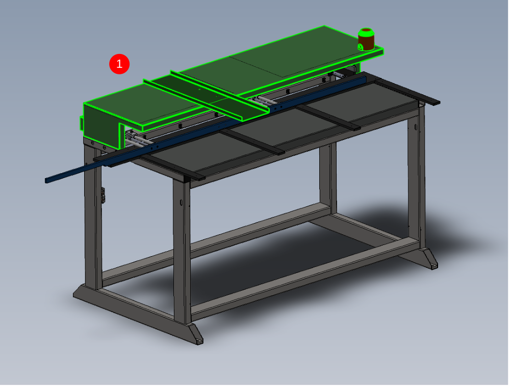
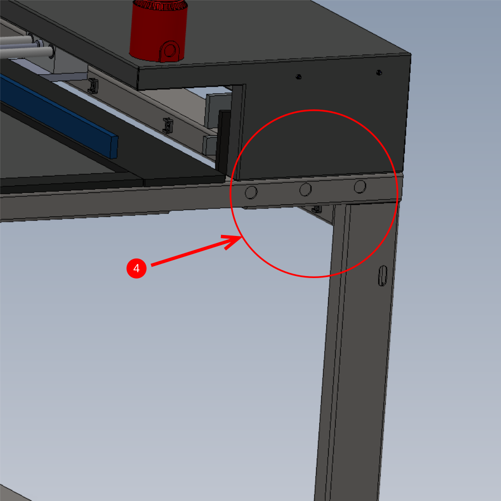
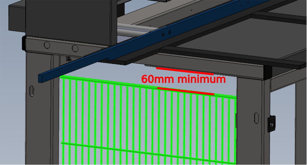
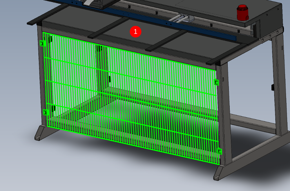
Étape 2 - Fit top Hood
1 Position top hood assembly as shown
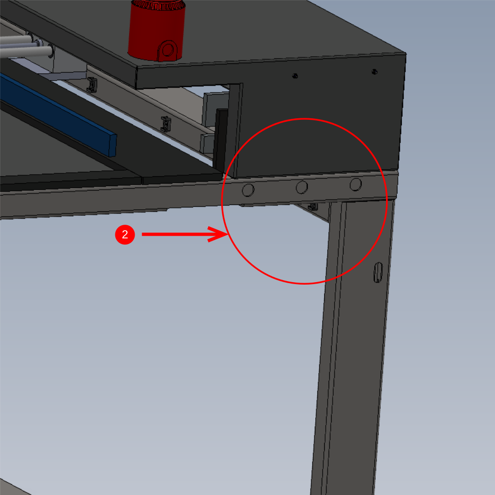
2 Slacken safety gate fixing 3 off M8 to allow access for cut guard mounting points
3 Use 4 off M6 x 20 Socket caps with M6 heavy motor washers and fit to indicated positions . Align as best as possible edges of cut guard to frame, then apply final tension to fasteners to complete
4 Finalise 3 off M8 socket caps that hold safety gate to frame
5 Run W00010002 cable into tie bases fitted to cut guard and route to Siren
(pictures please)
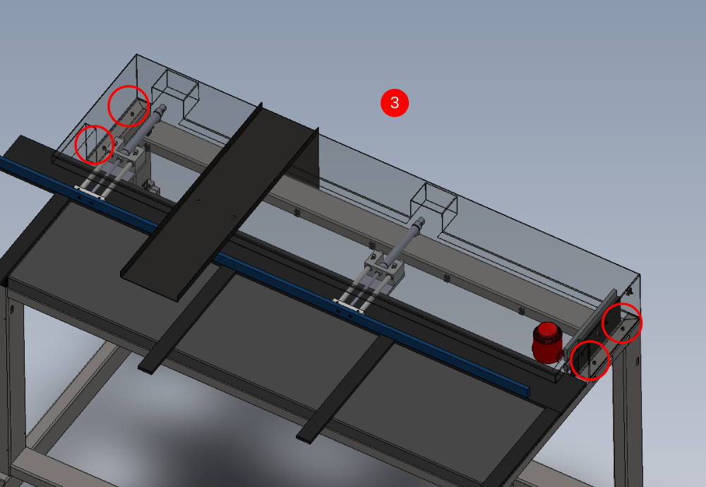
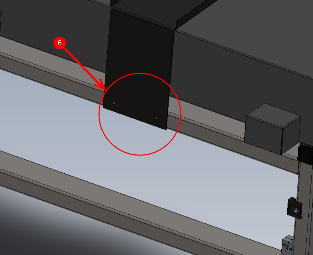
6 Add final fixings to printer shelf . Drill and tap to M8 and add 2 off M8 socket caps with A form washers
Étape 3 - Fit Printer
Fit printer to shelf as indicated
Ensure box is left on frame and auto peel is left with box

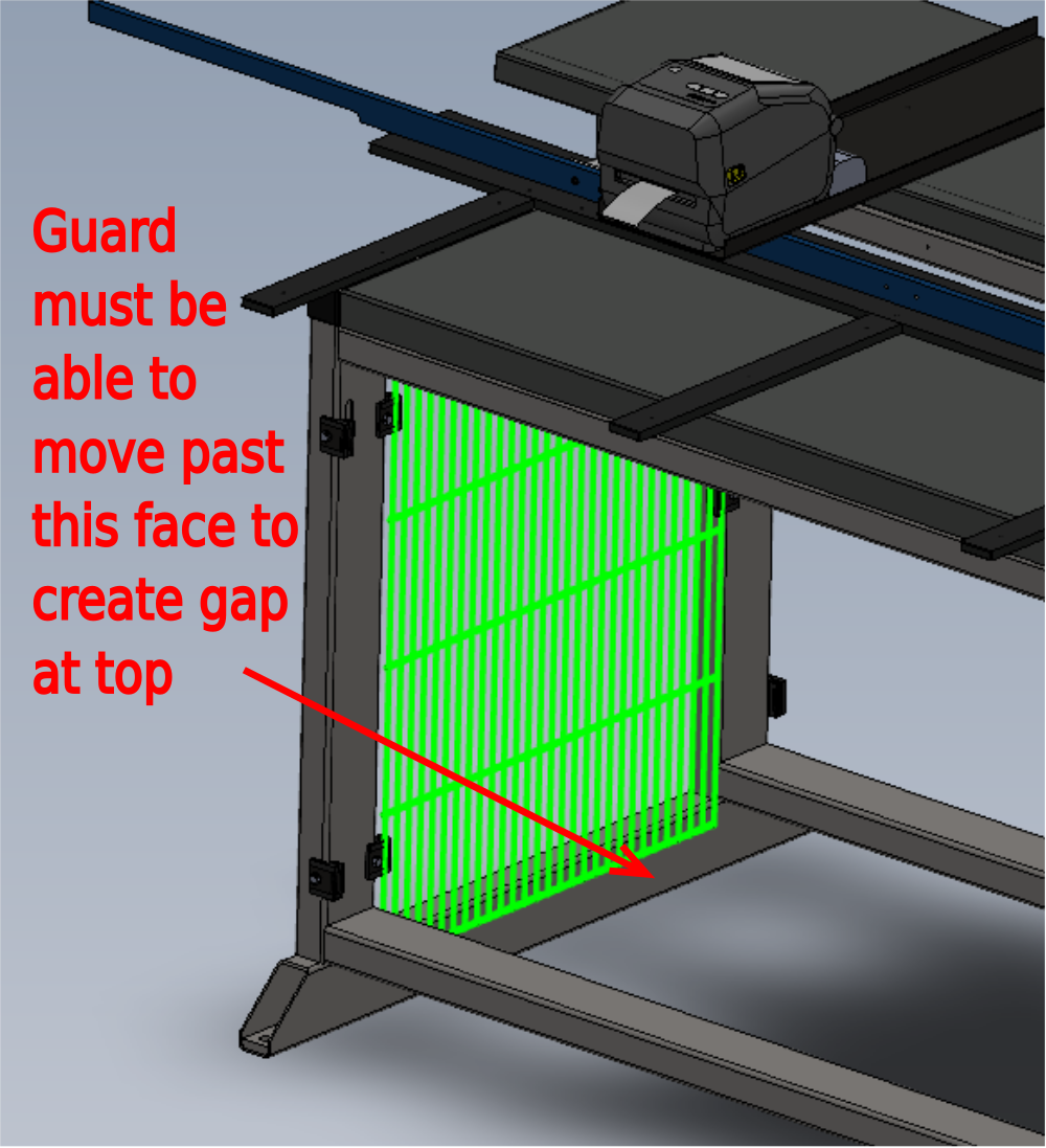
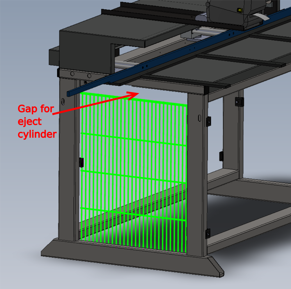
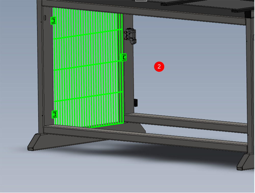
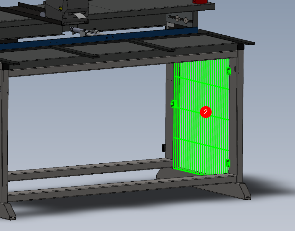
Étape 4 - Quality instance
Due to quality instance, one off guard panel must be able to be fitted to allow clearance for eject cylinder attached to saw module
On indicated guard panel, check that panel can be fitted as shown to allow adjustment
Étape 5 - Cut guard panels
D0016333 Bruehl Fence panel 1730 x 800 x 2
D0016334 Bruehl Fence panel 650 x 800 x 2
These panels will require cutting from sheet , ensure correct orientation of fence slats is obtained when marking out and cutting
See image for orientation

Étape 6 - Guard fitting
When fitting guards use alloy blocks and g clamps to hold guard to make fixing easier

Étape 7 - Attach guards to frame
1 Drill and fix front guard orientated as shown (hole sizes and bolt type required)
2 Drill and fix both side guards as shown (hole sizes and bolt type required)
3 Drill and fix read guard orientated as shown (hole sizes and bolt type required)


Draft
 Français
 English
 Deutsch
 Español
 Italiano
 Português