Installation details of waste guidance
Auteur  Gareth Green | Dernière modification 10/09/2025 par Gareth Green en cours de rédaction ⧼frevu-button-review-label⧽
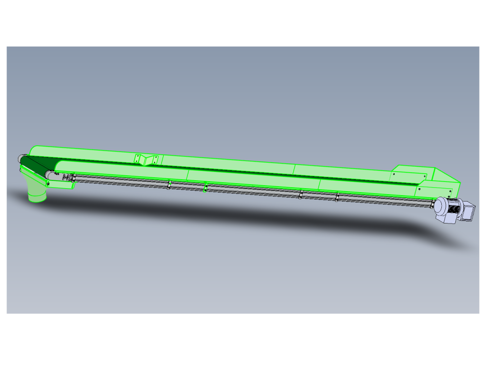
Installation details of waste guidance
R0015343_Waste_Guidance_Installation_Screenshot_2023-10-31_135102.png
en none 0 Draft
Vous avez entré un nom de page invalide, avec un ou plusieurs caractères suivants :
< > @ ~ : * € £ ` + = / \ | [ ] { } ; ? #
 Français
 English
 Deutsch
 Español
 Italiano
 Português