Assembly details for Module F cabinet pneumatics
Sommaire
- 1 Introduction
- 2 Étape 1 - Unless otherwise stated
- 3 Étape 2 - Handing
- 4 Étape 3 - Attach trunking
- 5 Étape 4 - Assemble Valvebanks
- 6 Étape 5 - Mount Valvebanks
- 7 Étape 6 - Assemble High Low pressure valve
- 8 Étape 7 - Mount valve to cabinet
- 9 Étape 8 - Mount connection points
- 10 Étape 9 - Attach beckhoff Boxes
- 11 Étape 10 - attach flow regulation
- 12 Étape 11 - Assemble Air service unit
- 13 Étape 12 - Mount air service unit
- 14 Commentaires
Introduction
Tools required
Tape rule
Steel rule
standard hex keys
Standard HSS drill set
Standard Tap set
Hack saw
Ball Pein hammer
Centre punch
Part Required
P0000010 Elbow Adaptor 6mm - 1/8 BSPT (Taper thread) x 3
P0000024 Fitting: Hex Nipple 1/4 BSP x 1
P0000096 Fitting: Brass Reducing Bush 1/2 - 1/4 x 2
P0000097 Fitting: Elbow Adaptor 8mm - 1/4 BSPT x 1
P0000159 Fitting: Stem Blanking Plug 6mm x 3
P0000160 Fitting: Flow Controller In Line 6mm x 2
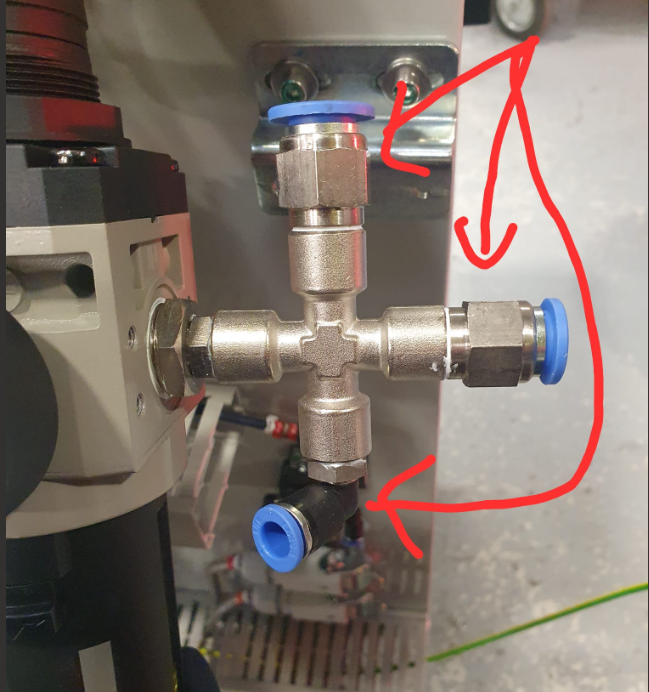
P0000279 Female Cross 1/4'' NPT x 1
P0000297 HighLow Pressure Valve x 1
P0000419 Air Service Unit OH (P0283)x 1
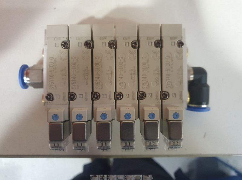
P0001070 Valve Base: Type 41 6 Position Ø6 x 2
P0001074 Fitting: 1/4" BSP Hex Head Silencer x 8
P0001101 Male straight 12mm to 1/4 bsp x 5
P0001102 Male elbow 12mm to 1/4 x 2
P0001186 Valve 24v dc SMC x 12
Étape 1 - Unless otherwise stated
All bolts to have Loctite 243 adhesive applied unless otherwise stated
All Threaded Pneumatic connections to have Loctite 570 applied
All bolts to be pen marked once adhesive applied and correct tension added
Étape 2 - Handing
Dokit will show configuration for R-L machine
Mirror mounting for all components for L-R configuration
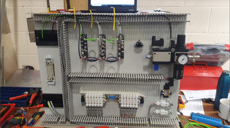
See reference photo
(please take photo of L-R config please )
Étape 3 - Attach trunking
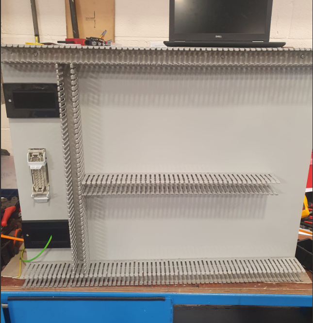
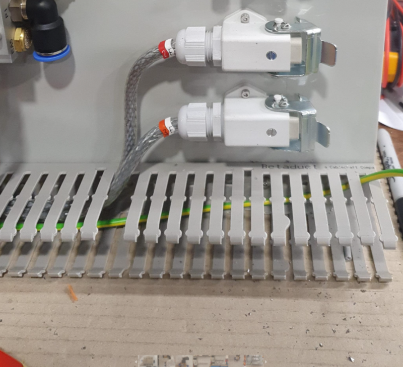
Cut trunking and fit to cabinet securing with M5 x 5 button heads fasteners
Holes will require adding by hand to cabinet to mount trunking
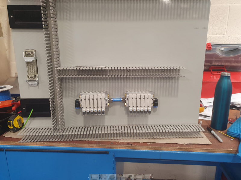
Étape 5 - Mount Valvebanks
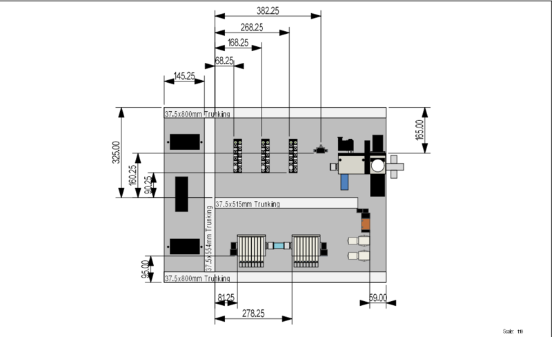
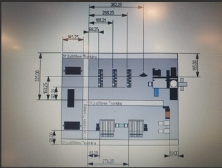
Drill Cabinet for mounting of valve banks in position shown
Use M4 x 40 socket caps and M4 A form washers to fix
Ensure 12mm blue pipe is added to pneumatically couple valve banks as shown
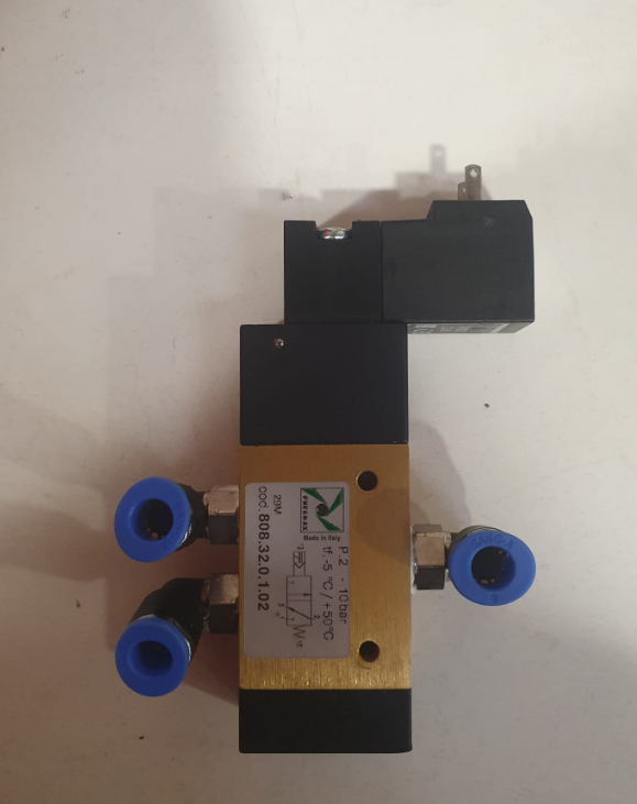
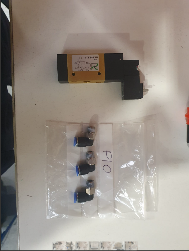
Étape 6 - Assemble High Low pressure valve
Assemble P0000297 valve with 3 off P0000010 air fittings as shown
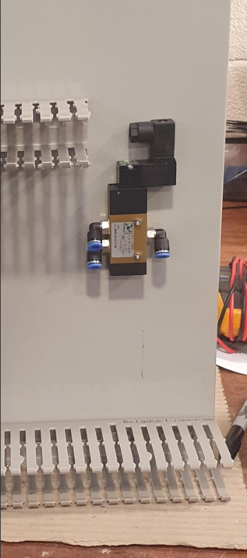
Étape 7 - Mount valve to cabinet
Mount valve to cabinet positioned as shown.
Use M3 x 25 socket caps to fix
Étape 8 - Mount connection points
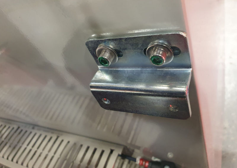
Drill and mount connection points as shown
Fix with M3 x 10 socket caps
Étape 9 - Attach beckhoff Boxes
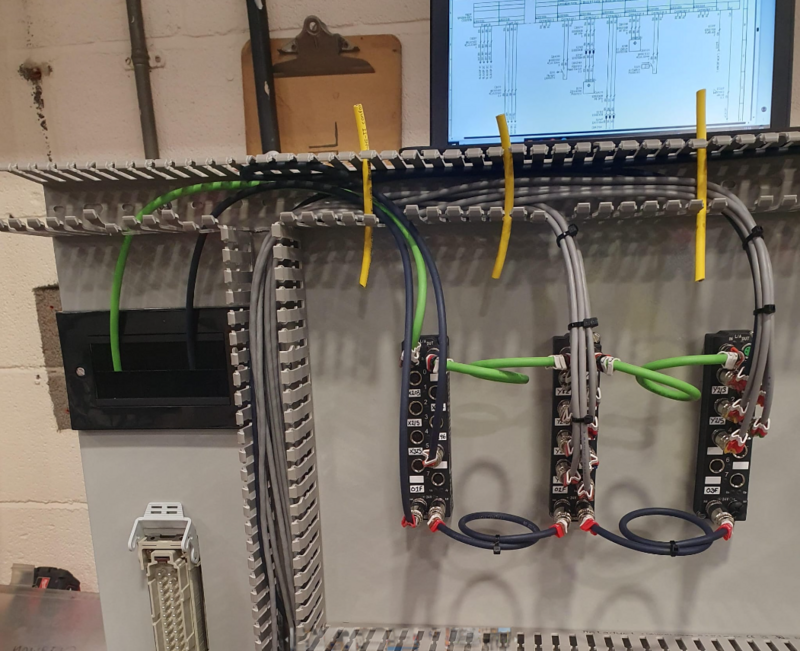
Drill cabinet and Attach ethercat boxes as shown
Use M3 x 25 pan head screws and M3 a form washers to mount
Étape 10 - attach flow regulation
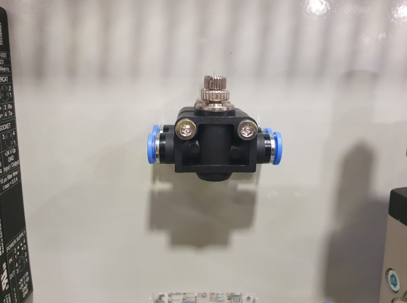
Drill and attach P0000160 flow regulators to cabinet
Fix with M4 x 40 socket caps
Étape 11 - Assemble Air service unit
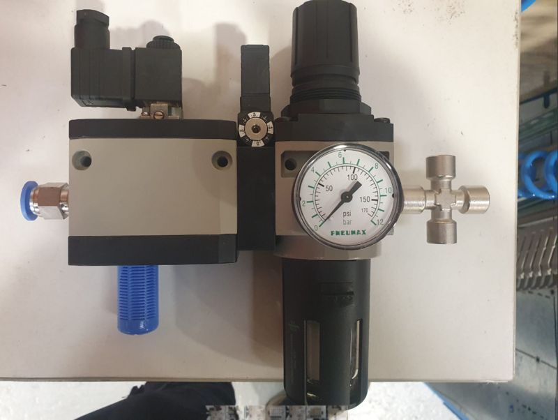
Assemble air service unit as shown
Ensure pressure adjustment dial and manual override are accesible from front face of unit
Étape 12 - Mount air service unit
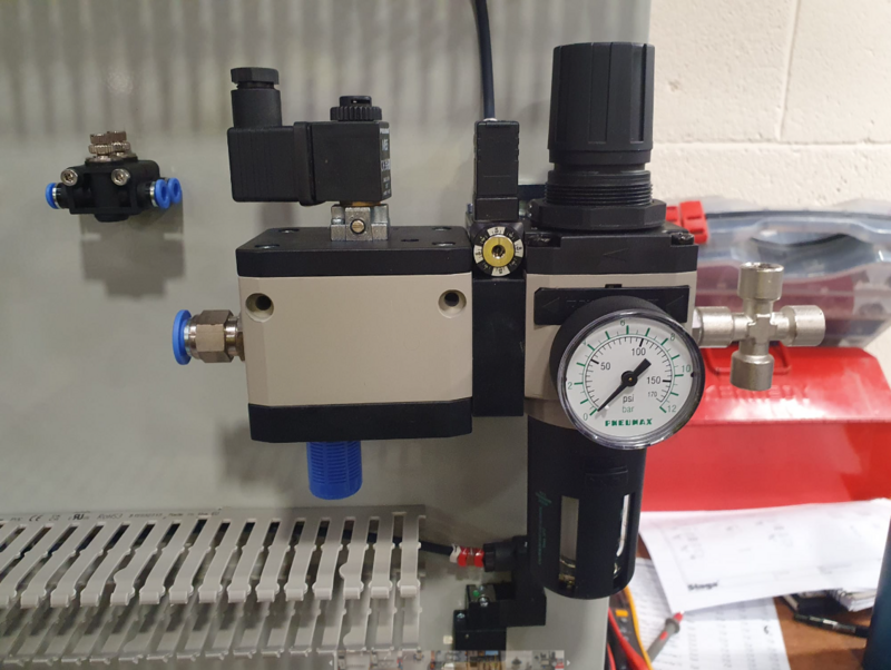
Mount air service unit in position shown
Use M5 x 12 socket caps with heavy M5 washers to fix bracket to cabinet
Use M5? x ? to secure air service unit to bracket
Draft


 Français
 English
 Deutsch
 Español
 Italiano
 Português