Pre Assembly of drive cylinders with sensors

Difficulté
Moyen
Durée
3 heure(s)
Sommaire
- 1 Introduction
- 2 Étape 1 - Unless otherwise stated
- 3 Étape 2 - All Air fittings must have sealant applied
- 4 Étape 3 - Mount single plunge home sensor
- 5 Étape 4 - Attach air fittings to single plunge cylinders
- 6 Étape 5 - Attach sensor bracket to Single plunge cylider
- 7 Étape 6 - Fit single out sensor
- 8 Étape 7 - Attach air fittings to double plunge cylinders
- 9 Étape 8 - Mount double plunge cylinder sensors
- 10 Étape 9 - Mount magnet to cylinder anchor
- 11 Étape 10 - Fit Cylinder push arm nut to cylinder
- 12 Étape 11 - Finalise Cylinder push arm nut
- 13 Étape 12 - Check correct operation
- 14 Commentaires
Introduction
Tools Required
Standard spanner set
Small screwdriver set
Reed switch test box
Araldite 2 part adhesive
Parts Required
D0015540 sensor bracket x 8
P0000488 Sensor x 8
P0001098 elbow adapter x 12
P0000238 6mm elbow x 8
P0001198 6mm flow elbow x 8
P0000459 4mm elbow x 4
P0001202 4mm flow elbow x 4
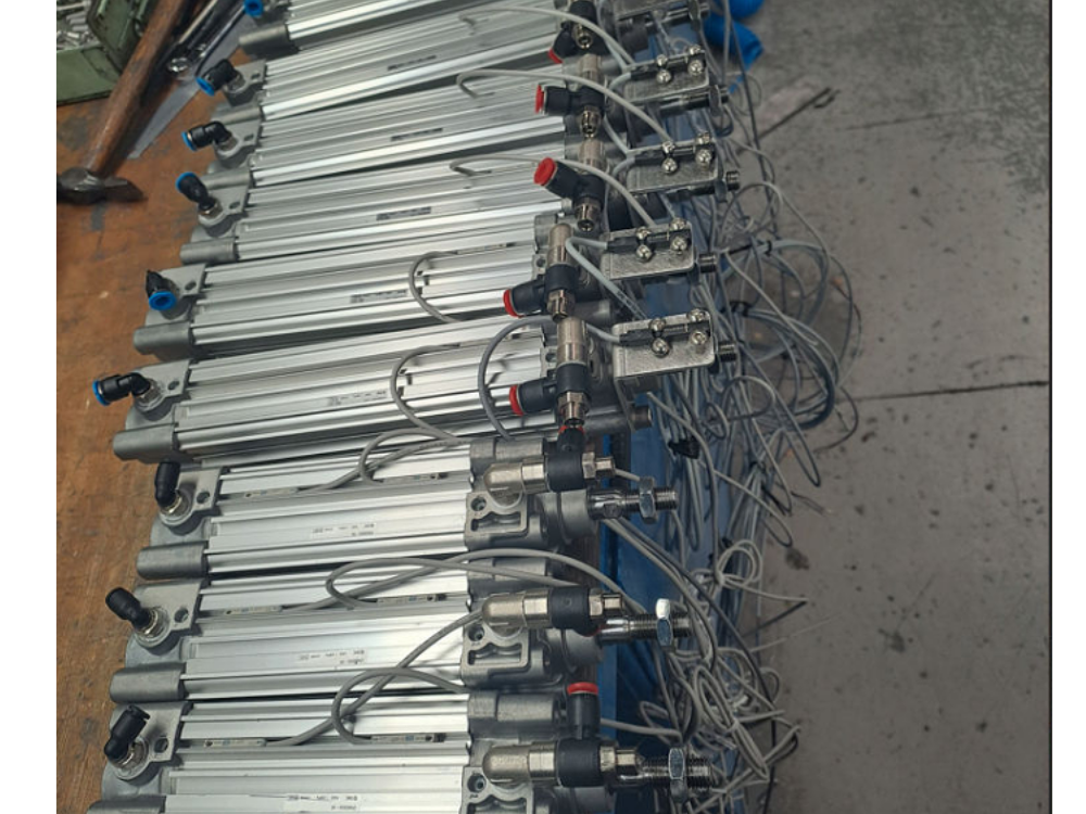
P0001200 cylinder x 8
P0001201 cylinder x 4
P0001047 reed switch x 16
D0016339 cylinder anchor x 8
D0016340 Cylinder push nut x 8
M0001170 magnet x 8
Étape 1 - Unless otherwise stated
Loctite 243 must be used on all bolts
Bolts must be pen marked when finalised

Étape 2 - All Air fittings must have sealant applied
All threaded pneumatic fittings MUST have adequate Loctite572 applied
The ring has an anti drop system for tooling on emergency stop, and presence of any air leaks will affect this feature

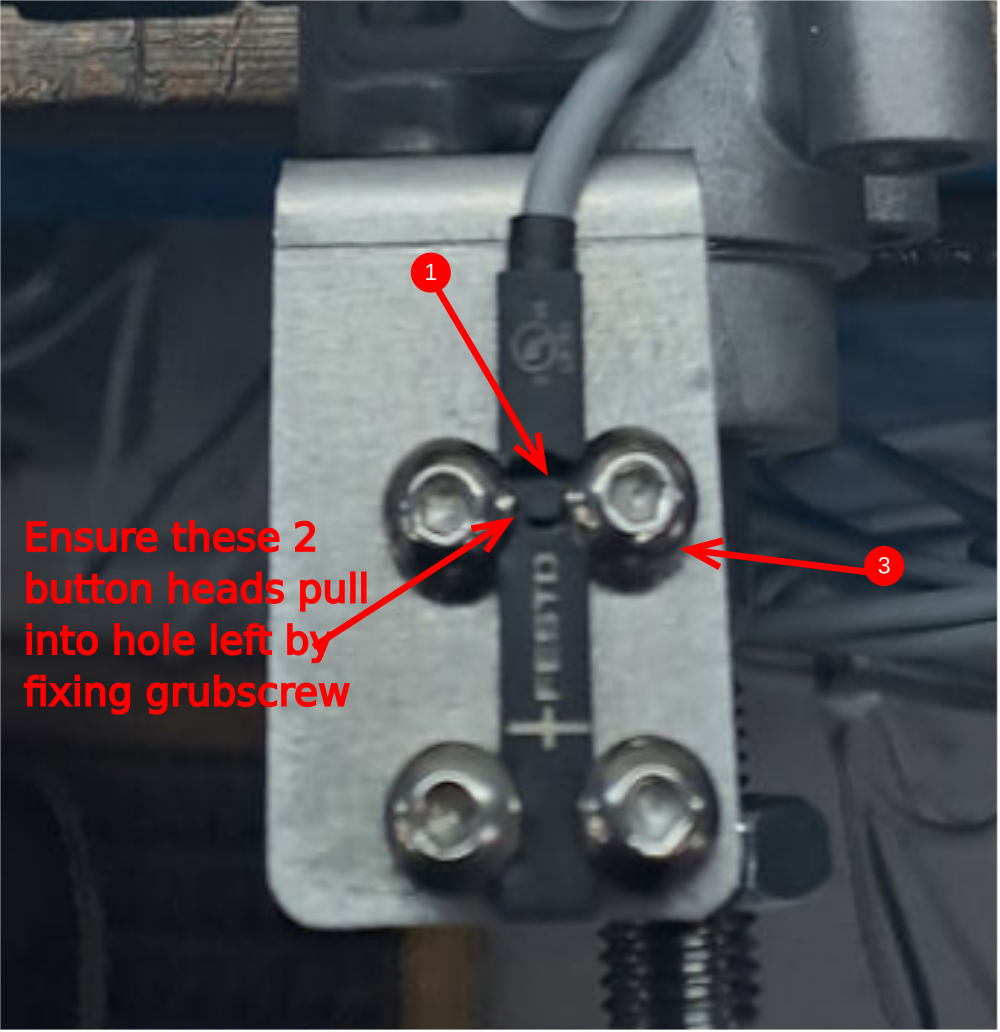
Étape 3 - Mount single plunge home sensor
8 off
1 Remove OEM sensor locking nut from sensors P0000488
2 Label sensors at trailing end SH
3 Use m4 x 6 button heads and attach sensor to D0015540 as shown
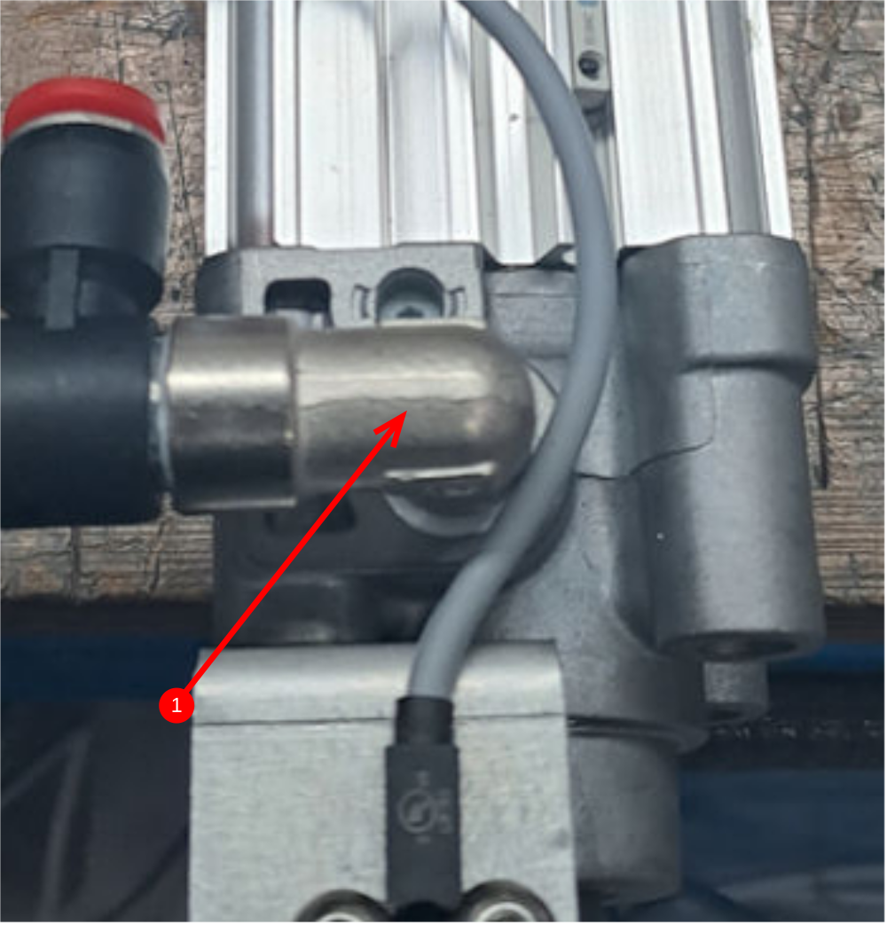
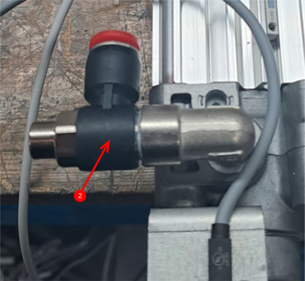
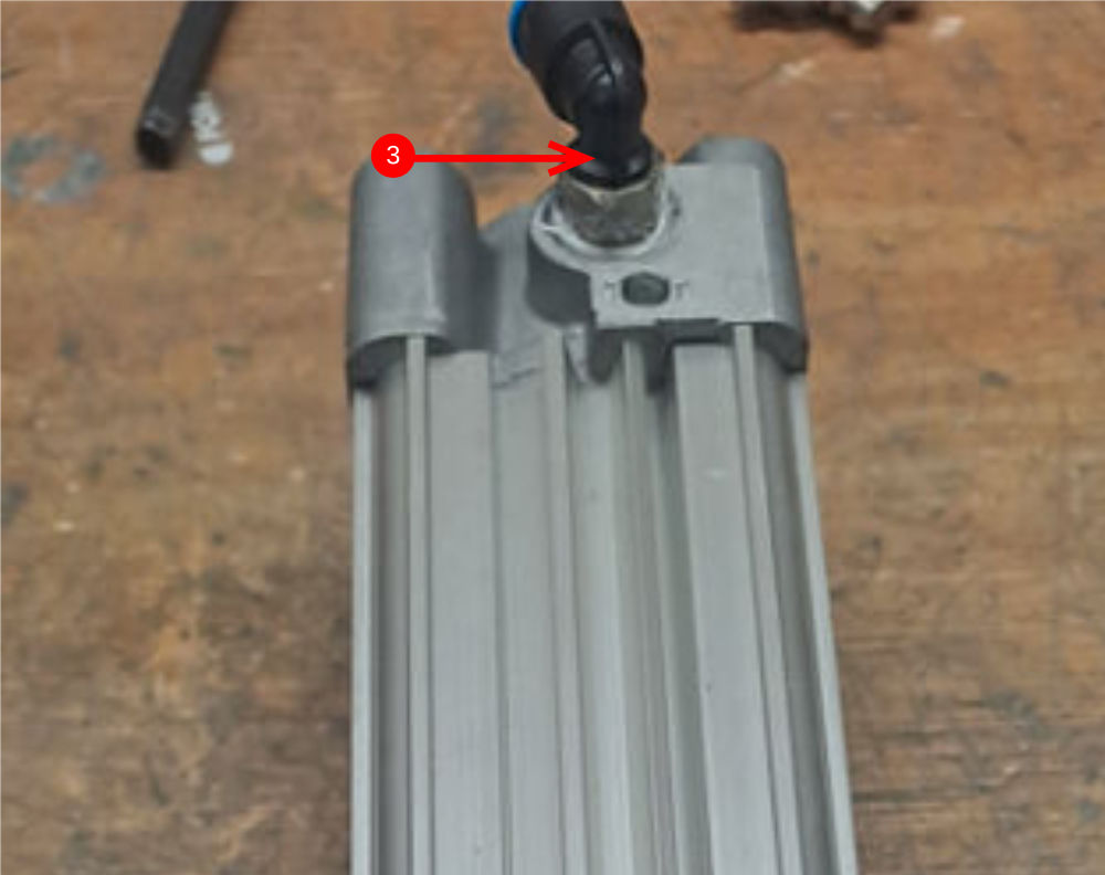
Étape 4 - Attach air fittings to single plunge cylinders
8 off P0001200 cylinder
Use Loctite 572 on all air fittings
1 Attach P0001098 elbow as shown
2 Attach P0001198 elbow
3 Attach P0000238 elbow
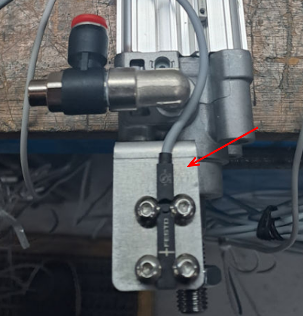
Étape 5 - Attach sensor bracket to Single plunge cylider
8 off
Use 2 off m6 x 16 socket caps to attach sensor bracket to cylinder
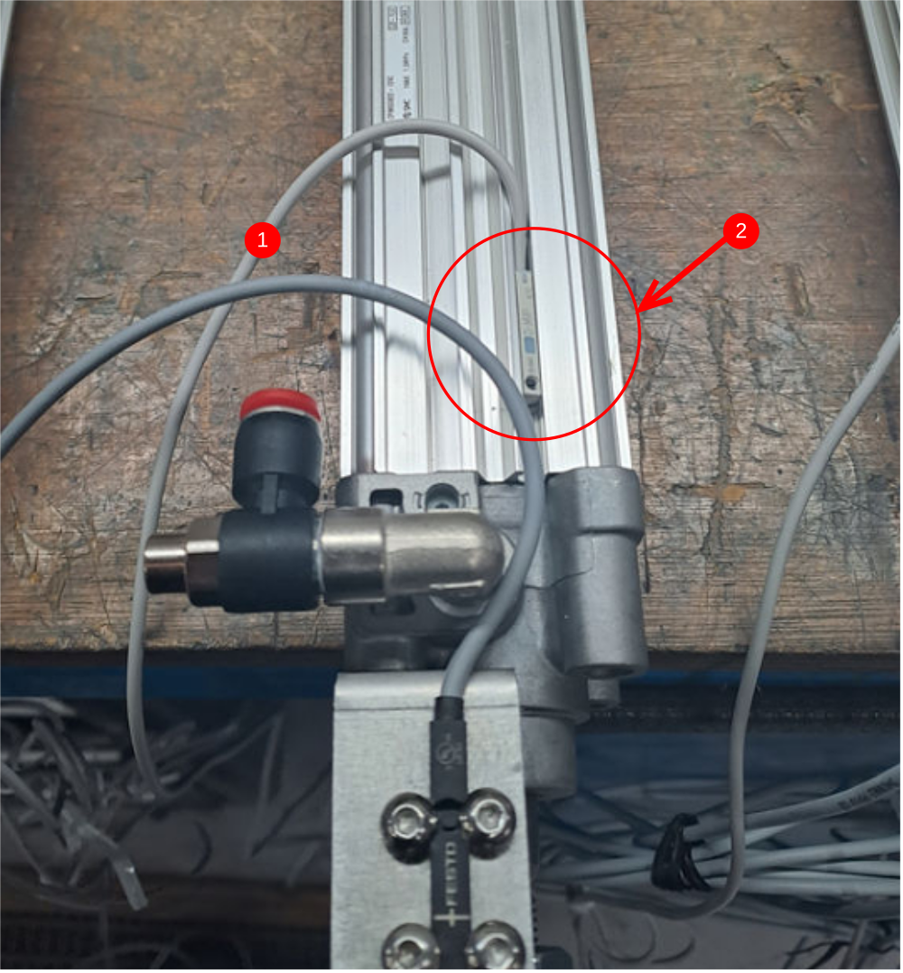
Étape 6 - Fit single out sensor
8 off
1 label 8 off P0001047 sensor SO at connection end
2 Use test box and connect sensor and set position on cylinder with piston extended out of cylinder
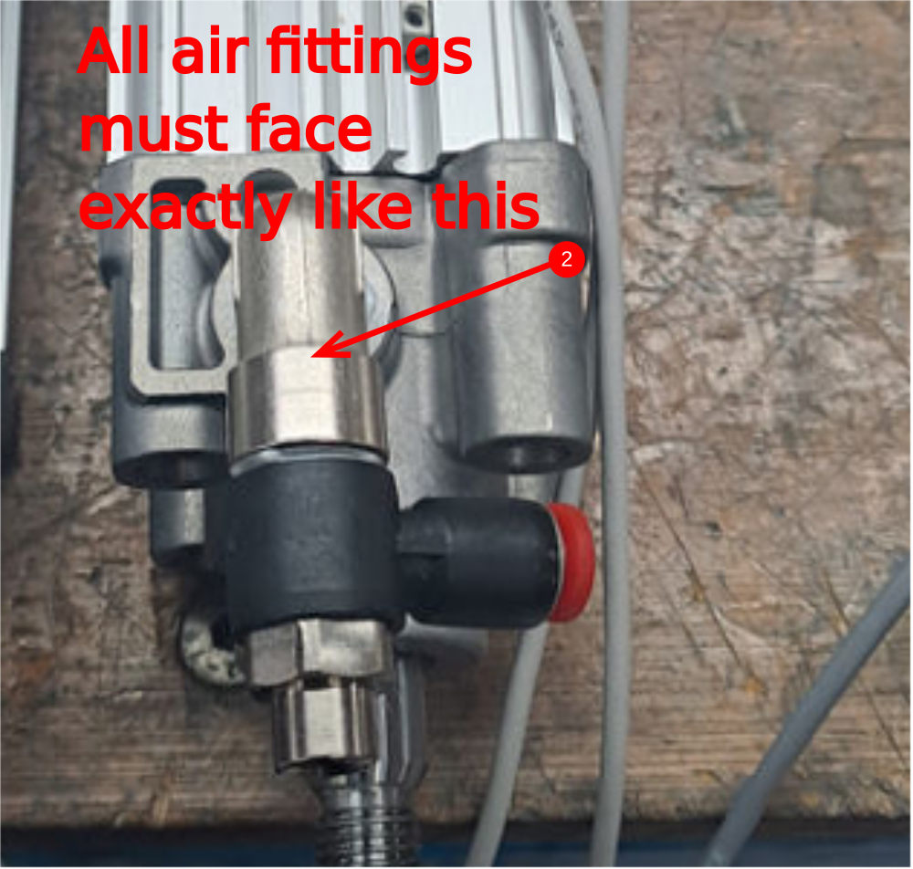
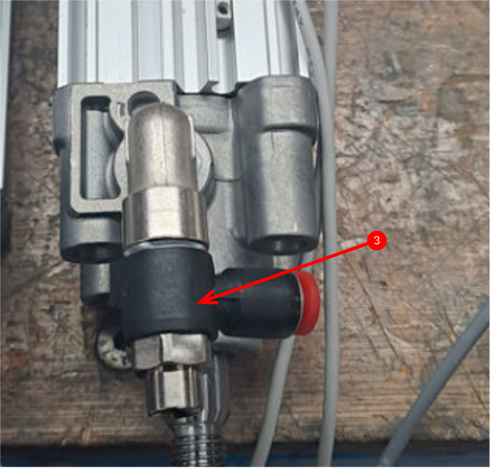
Étape 7 - Attach air fittings to double plunge cylinders
Use Loctite 572 on all air fittings
4 off Cylinder P0001201
1 Attach P0000459 4mm elbow
2 Attach P0001098 elbow
3 Attach P0001202 flow regulator elbow

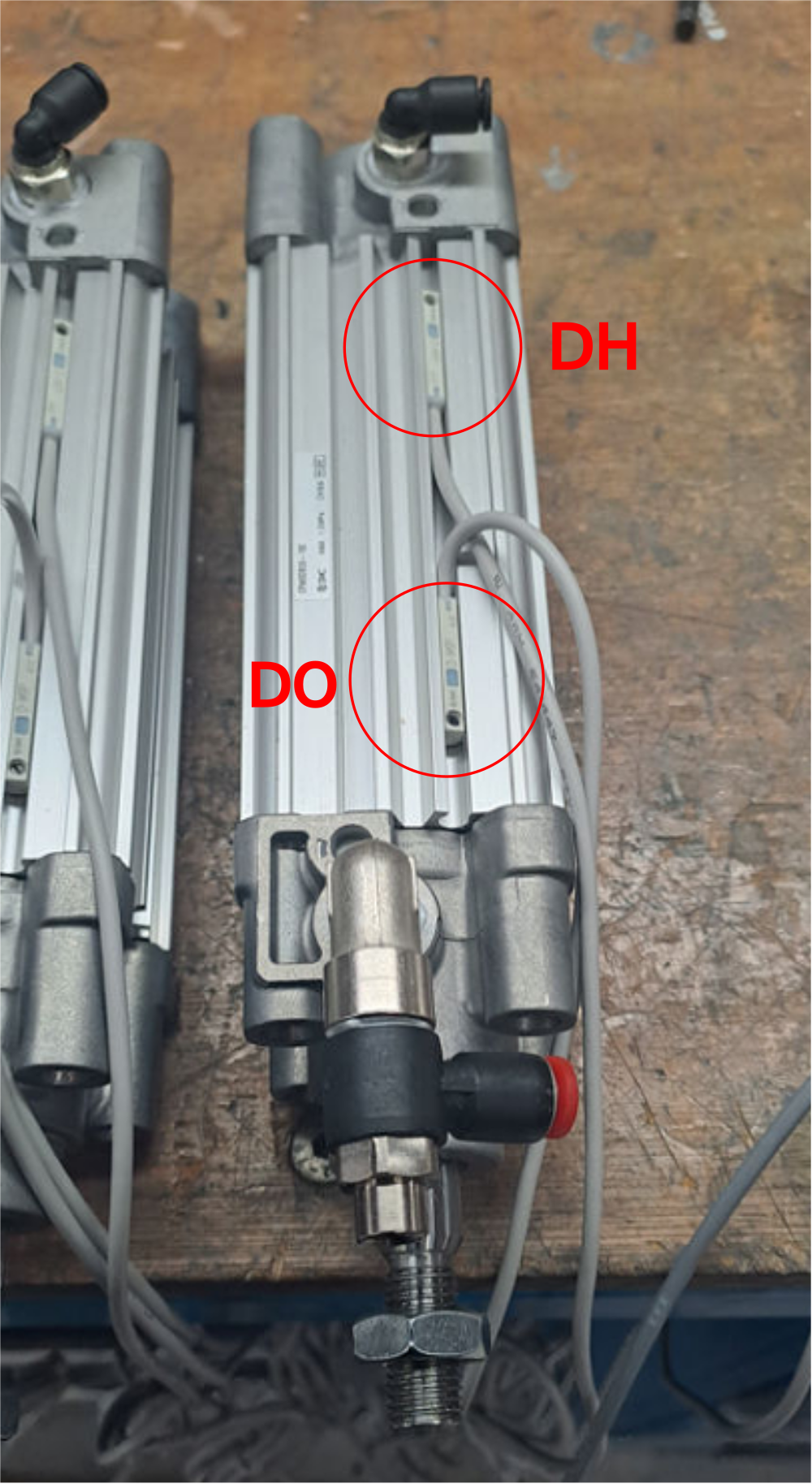
Étape 8 - Mount double plunge cylinder sensors
Mark 4 off sensors P0001047 at connection end DO
Mark 4 off sensors P0001047 at connection end DH
Use test box and set reed switches in position on cylinders orientated as shown in picture
Étape 9 - Mount magnet to cylinder anchor
M0001170 magnet must have additional 2 part adhesive (araldite ) applied to be adequately attached to D0016339 cylinder anchor

Étape 10 - Fit Cylinder push arm nut to cylinder
1 Remove cylinder lock nut from end of cylinder and use FE10 solvent to degrease cylinder thread
2 Apply loctite 243 to cylinder thread and fit D0016340 cylinder push arm and locate against cylinder piston thread shoulder as shown


Étape 11 - Finalise Cylinder push arm nut
Apply Loctite 243 to exposed cylinder thread and also M10 locking nut
Fit nut to cylinder thread and apply light tension to secure the nut against the cylinder push arm nut


Étape 12 - Check correct operation
1 D0016339 bracket should be trial fitted to the cylinder assembly as shown
2 Cylinder bracket shown must be able to be moved in all directions shown to ensure correct operation
Check for all assembled cylinders


Draft
 Français
 English
 Deutsch
 Español
 Italiano
 Português