Fitting of control pipes and connections

Difficulté
Difficile
Durée
4 heure(s)
Sommaire
- 1 Introduction
- 2 Étape 1 - unless otherwise stated
- 3 Étape 2 - Quality
- 4 Étape 3 - Mount Single plunge valves
- 5 Étape 4 - Mount Double plunge valves
- 6 Étape 5 - Air Feed connections
- 7 Étape 6 - Exhaust line fittings
- 8 Étape 7 - Exhaust line pipes
- 9 Étape 8 - Cylinder connections
- 10 Étape 9 - Cylinder connections
- 11 Étape 10 - Cylinder connections
- 12 Étape 11 - Quality
- 13 Étape 12 - Valve connections
- 14 Étape 13 - Valve connections
- 15 Étape 14 - Route single slide 300hz
- 16 Étape 15 - Loom sensors
- 17 Étape 16 - Connect 4mm air pipes
- 18 Commentaires
Introduction
Tools Required
Pipe cutters
Standard screwdriver set
Standard hex key set
Standard spanner set
Parts Required
D0010807 upstand collar x 32
P0001023 6mm compact y x 4
P0000456 M5-4mm straight fitting x 24
P0001091 Bulkhead 6mm straight x 24
P0001093 6mm - 4mm stem elbow x 8Étape 1 - unless otherwise stated
Use Loctite 243 on all fasteners
Pen mark all fasteners to show finalised

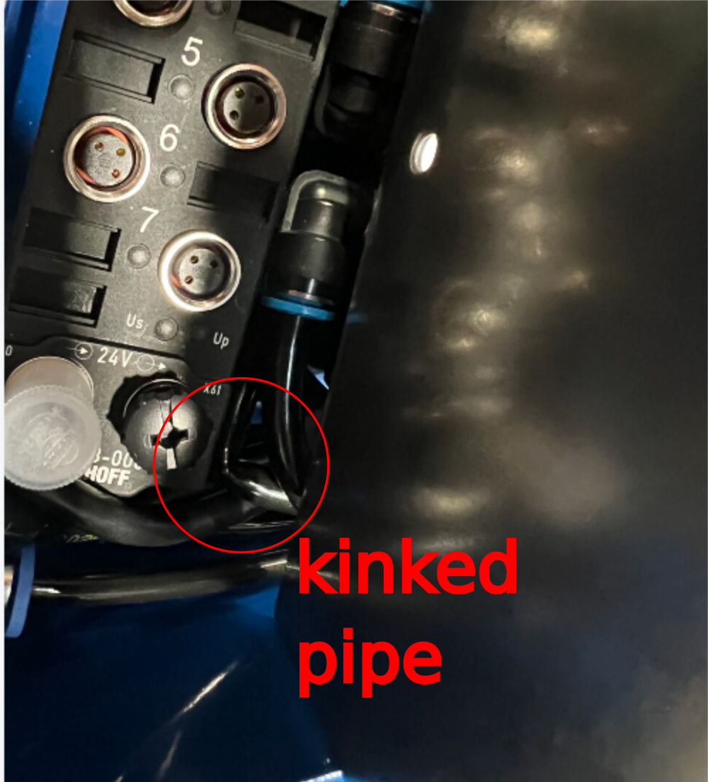
Étape 2 - Quality
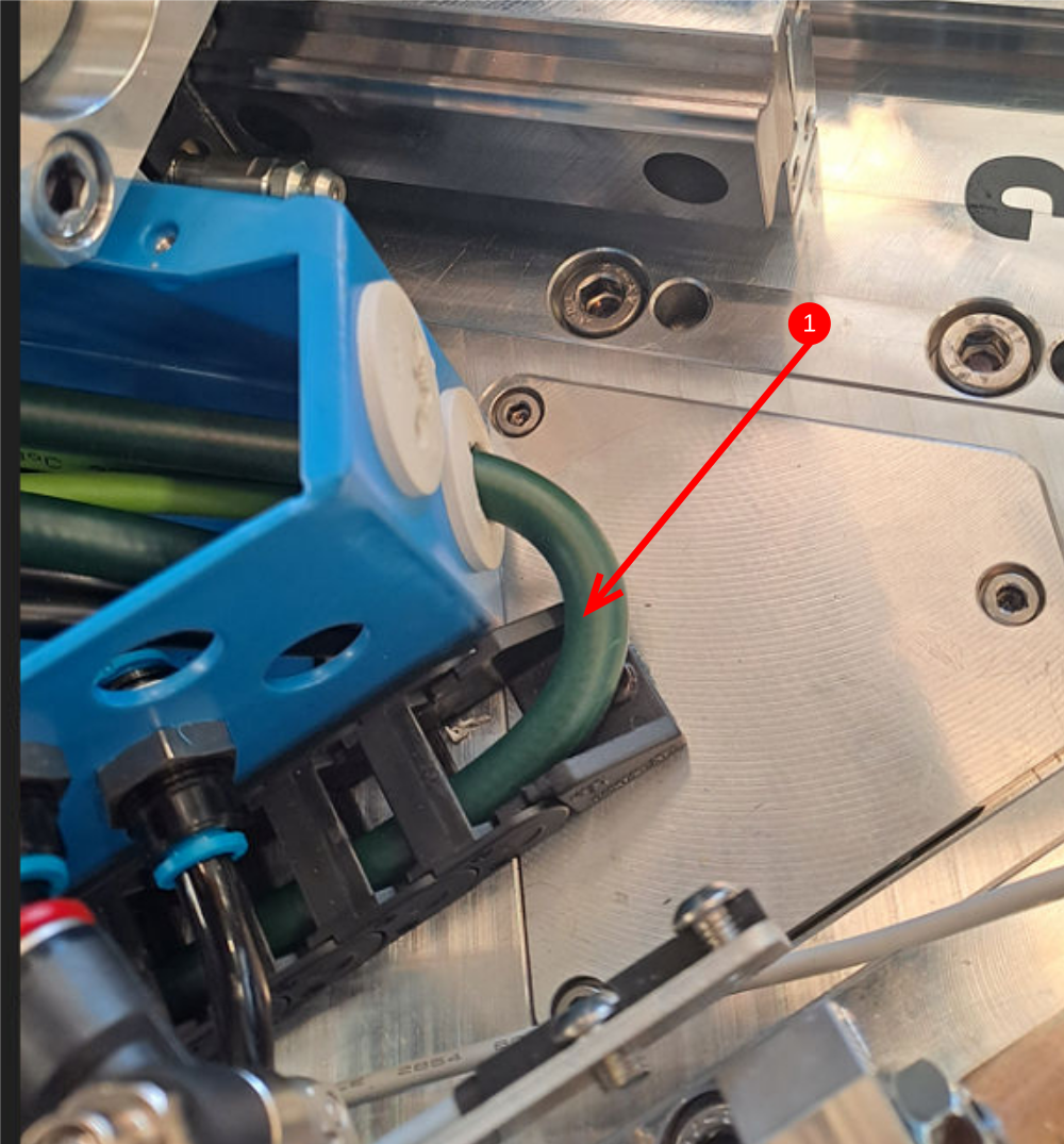
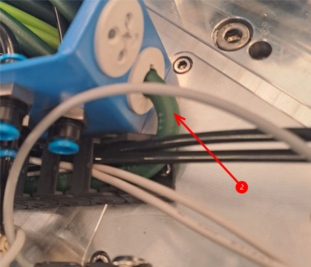
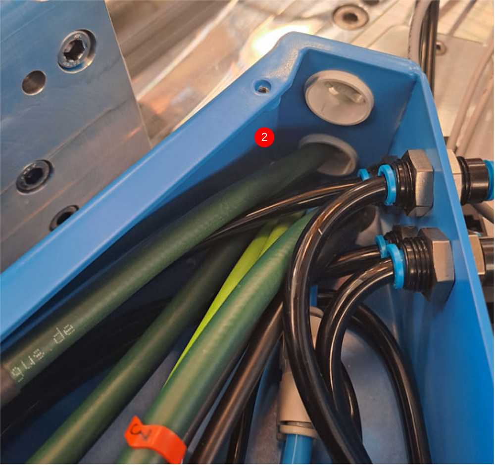
It is vital that no air pipes are kinked on installation .
Ensure all pipes are checked for correct running .
Example attached of kinked pipe

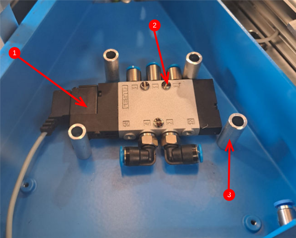
Étape 3 - Mount Single plunge valves
4 off
1 Mount pre assembled valve into spindle connection boxes to the left of the single slide spindle assembly (as viewed from rear)
2 Use 3 off M3 x 12 pan heads to secure valve to connection box as shown
3 Before tightening, add 4 off D0010807 upstand collars to define position of valve mounting
4 Finalise fixing
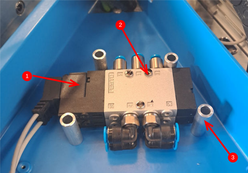
Étape 4 - Mount Double plunge valves
4 off
1 Mount double stack of valves into spindle boxes to the left of the double plunge spindle assemblies. (as viewed from rear)
2 Use 3 off M3 x 25 pan heads to secure valve to connection box as shown
3 Before tightening, add 4 off D0010807 upstand collars to define position of valve mounting
4 Finalise fixing
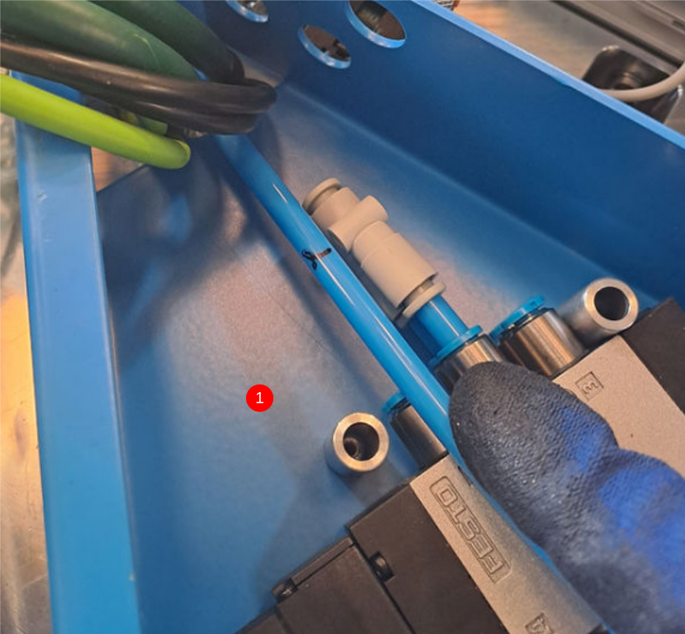
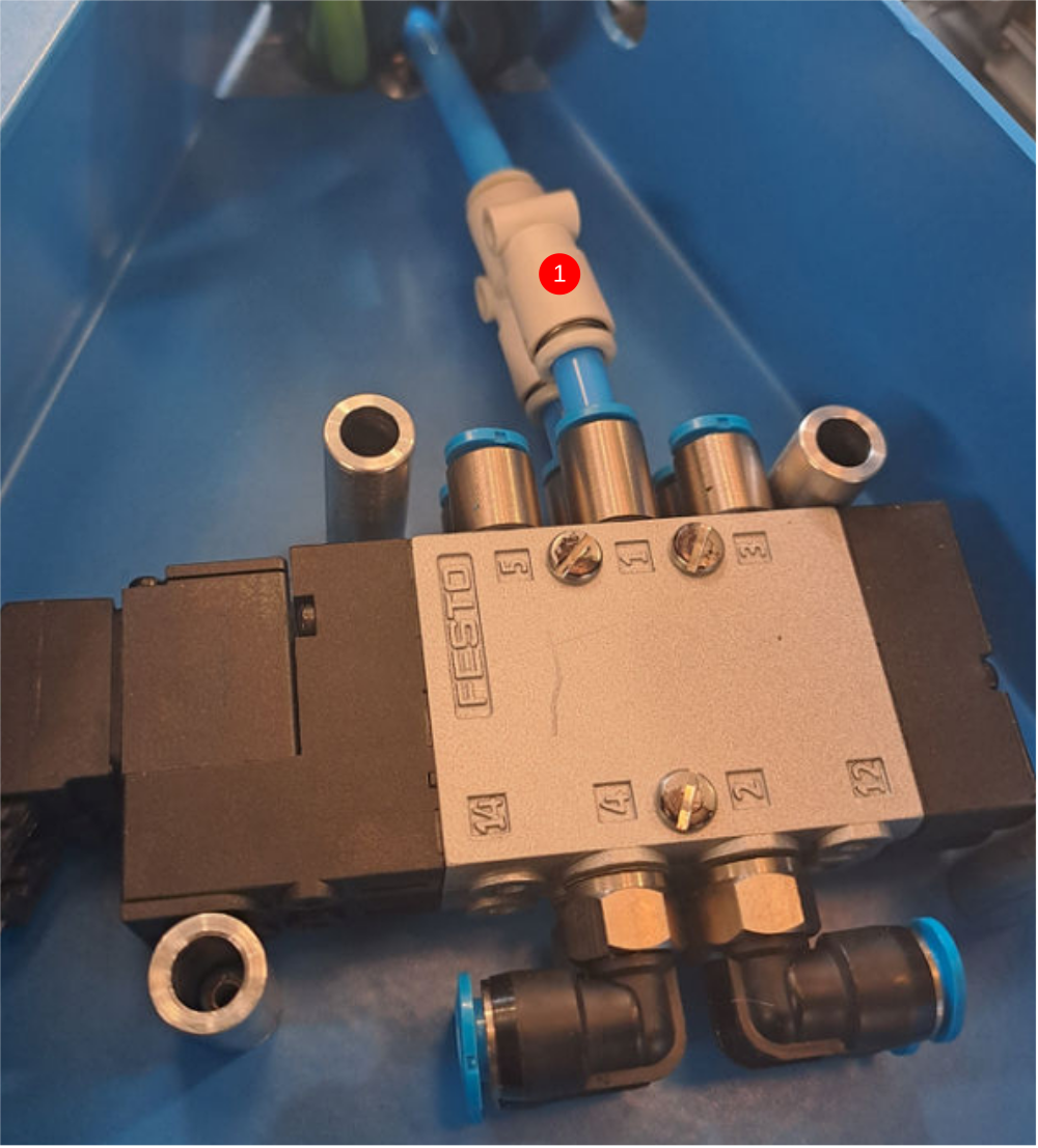
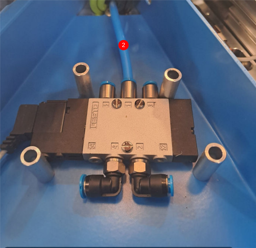
Étape 5 - Air Feed connections
1 Double valve connections
Use compact 6mm tee P0001023 and connect two valves together as picture
Lay feed pipe over top and mark length, cut and connect
2 Single valve connections
Lay feed pipe over valve fitting, mark and cut then connect
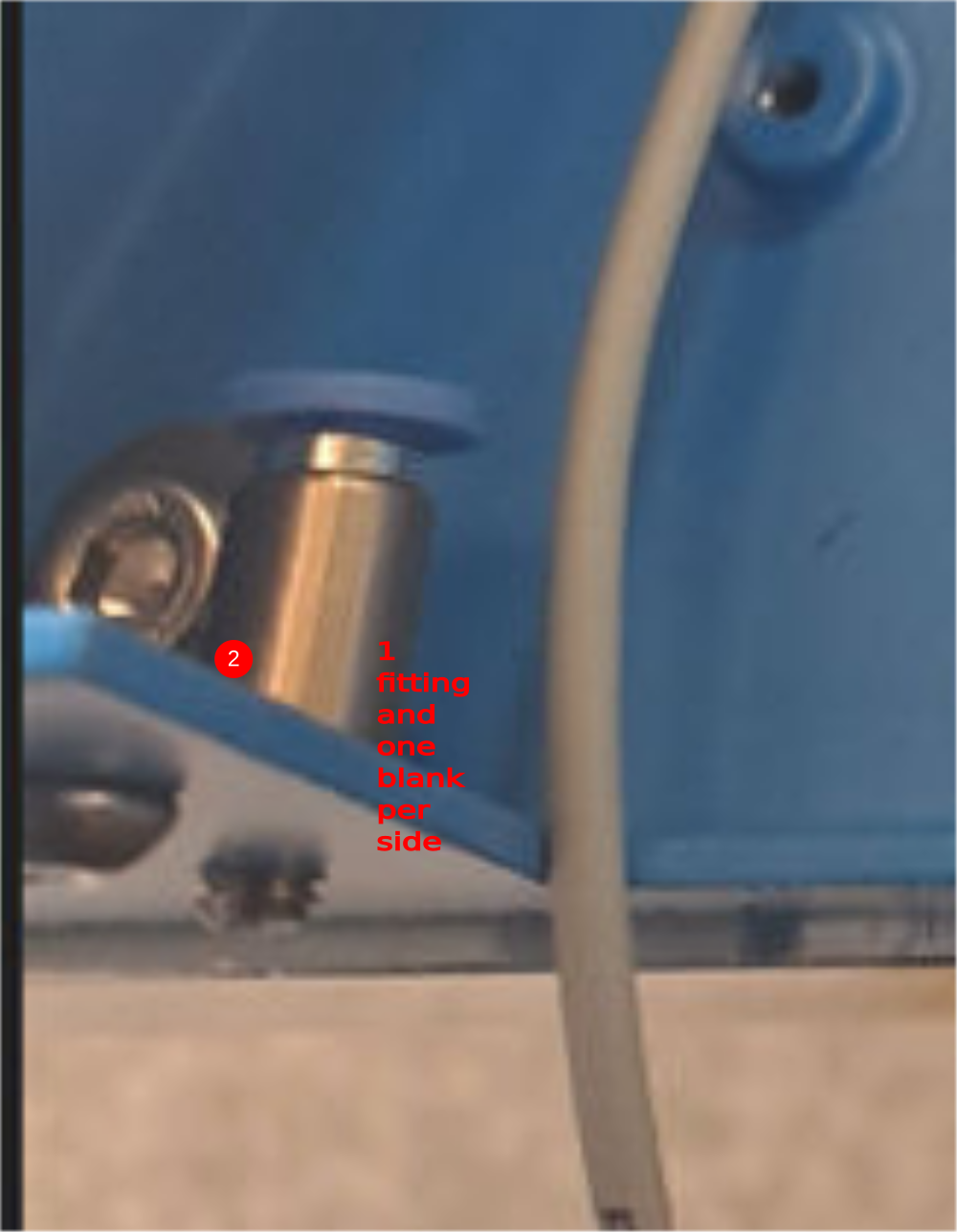
Étape 6 - Exhaust line fittings
1 Fit 4 off P0000456 m5 -4mm straight fittings to double plunge connection boxes ( 2 valve boxes)
2 Fit 2 off Poooo456 m5-4mm straight fittings to single plunge connection boxes (1 valve boxes) and 2 off M5 x5 button heads as blanks
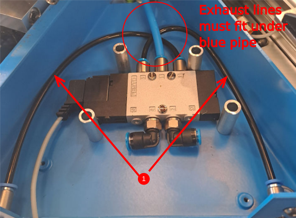
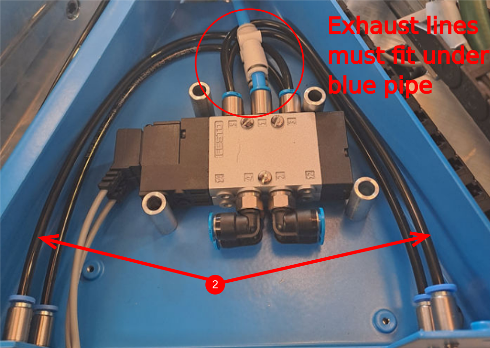
Étape 7 - Exhaust line pipes
1 Use 4mm black air pipe to connect lower valve in all connection boxes as shown
2 On double valve boxes overlay second set of pipes to connect exhausts of top valve
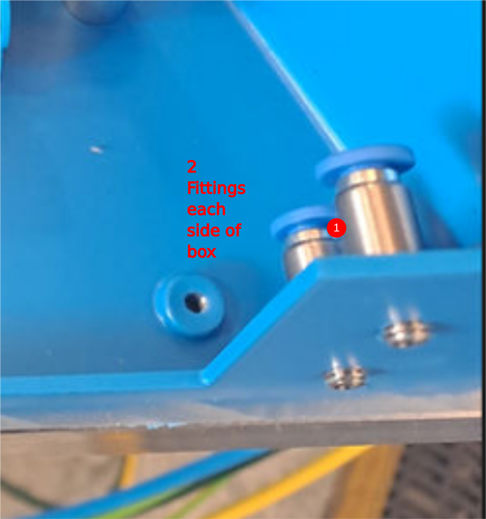
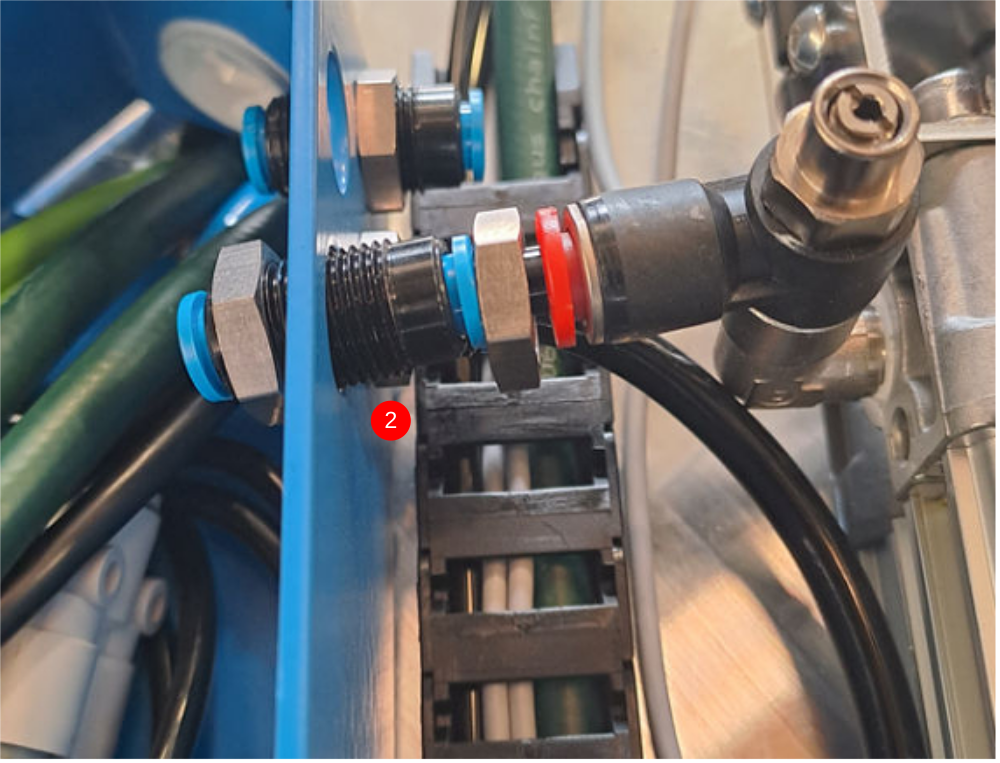
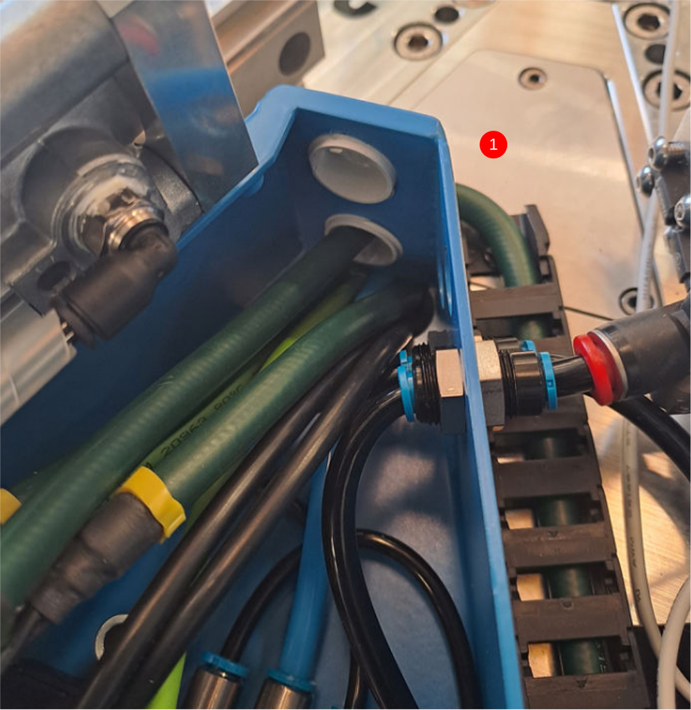
Étape 8 - Cylinder connections
1 Fit P0001091 bulkhead connector to all spindle boxes at position shown, ensuring orientation of bulkhead is the same
2 Cut 8 pieces of black 6mm air pipe @230mm long and fit as show
3 Add P0001091 bulkhead to double slide connection boxes only as shown
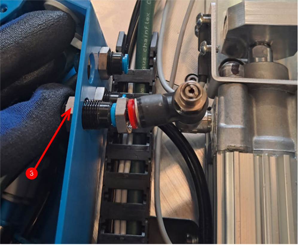
Étape 9 - Cylinder connections
1 Prepare 8 off P0001091 bulkheads with a piece of 32mm long 6mm black pipe added and one nut removed
2 Push pipe into cylinder fitting with nuts loose as shown
3 Apply force on fitting towards cylinder and run indicated nut to face to ensure no strain is added to fitting when tightening
4 Spin indicated nut to the connection box face and then tighten nuts
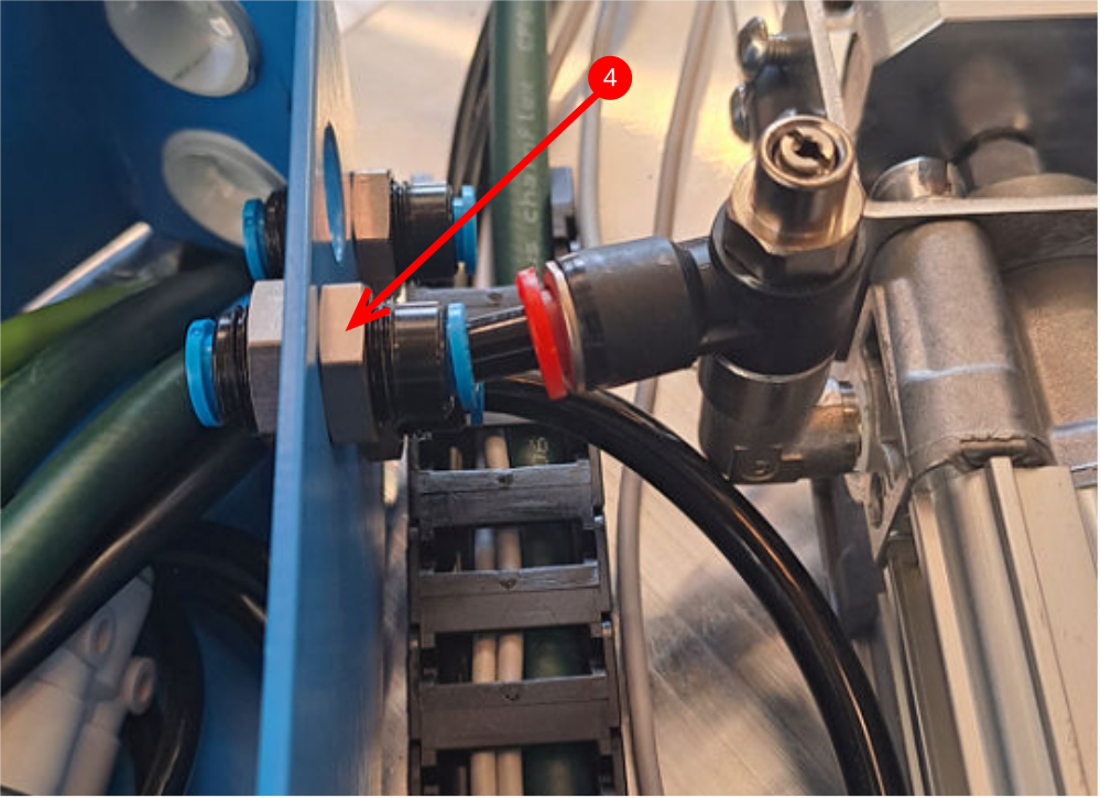
Étape 10 - Cylinder connections
Fit remaining p0001091 bulkhead to double slide connection boxes as shown
Étape 11 - Quality
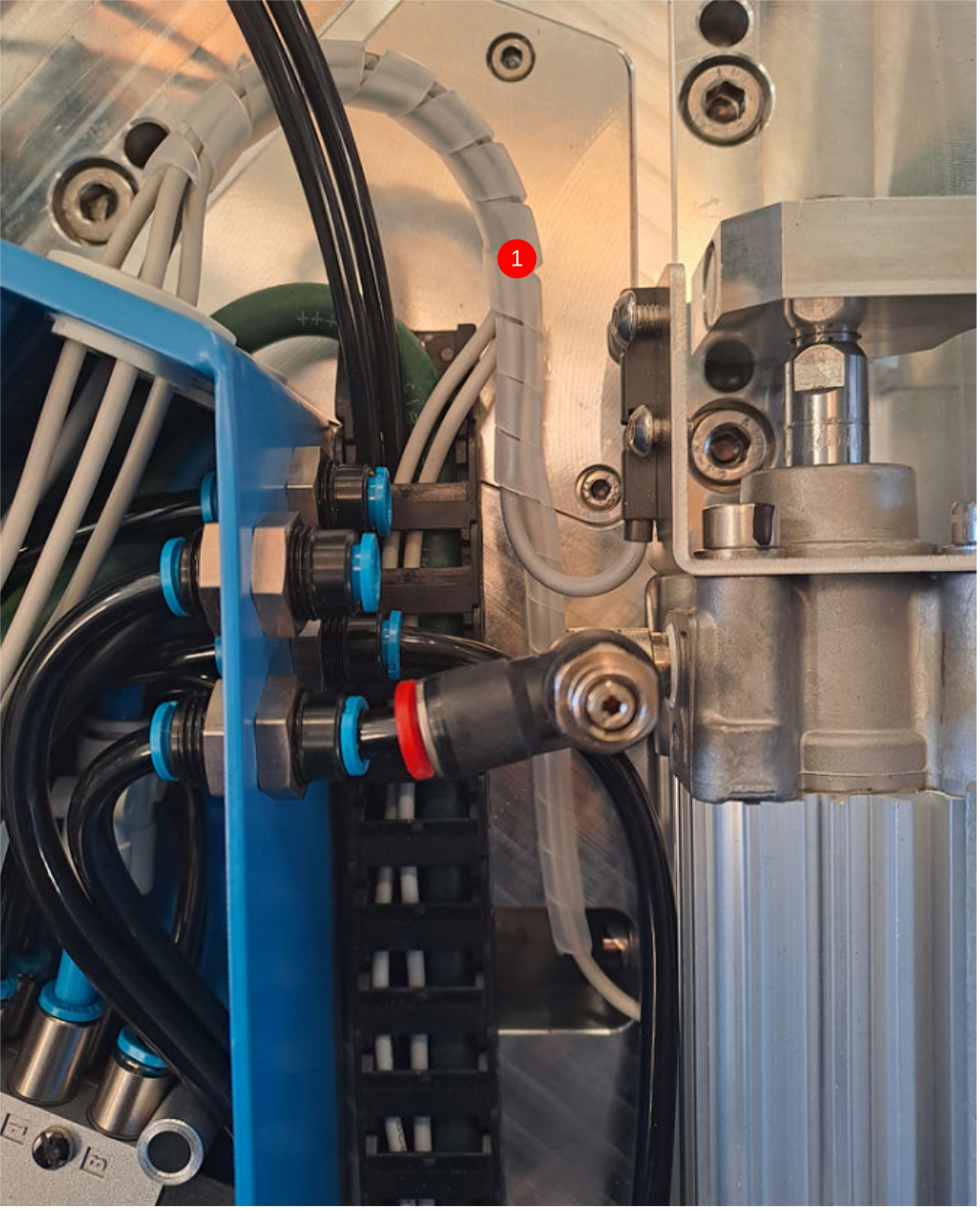
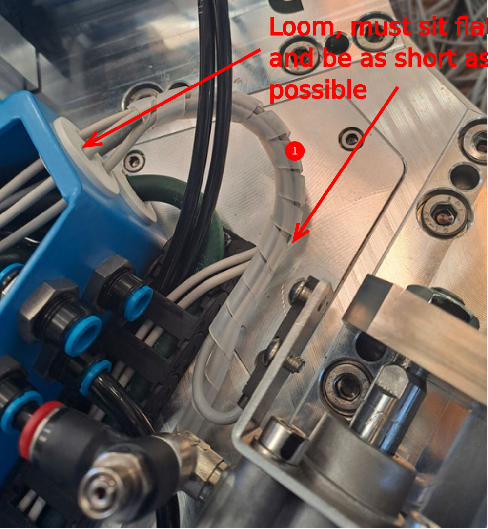
Please ensure all looms created and run are identical on each spindle head and copy examples shown . Looms must be kept to minimal size to protect from debris during operation
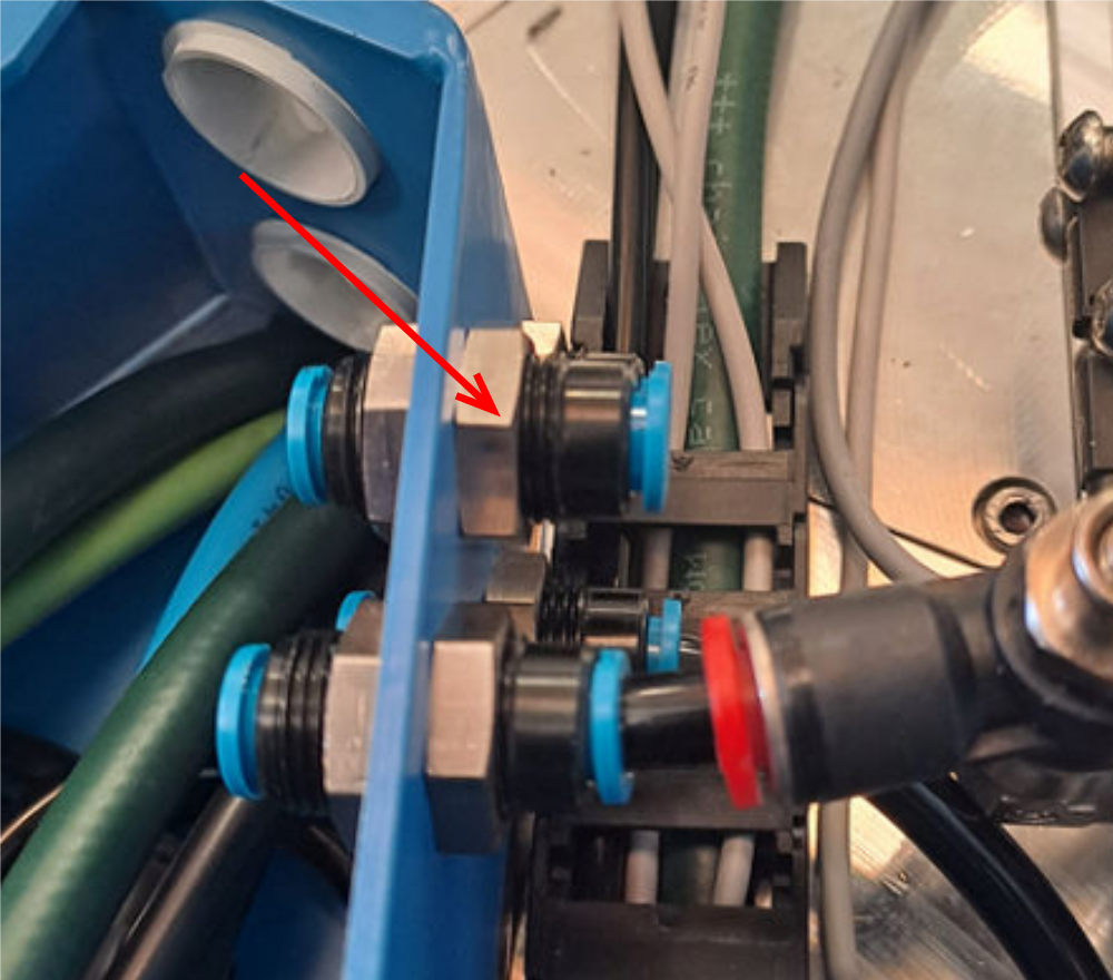
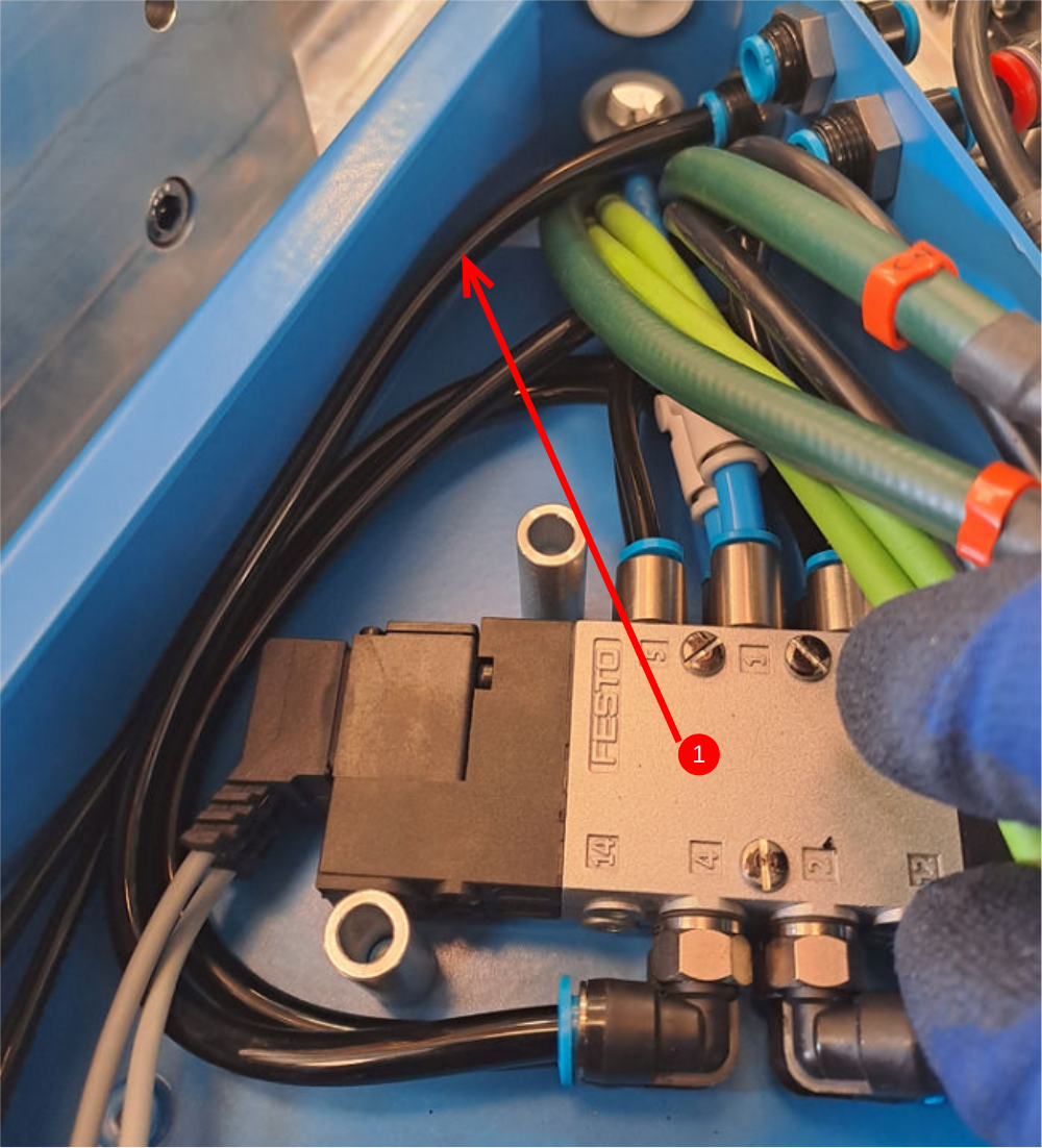
Étape 12 - Valve connections
1 Cut 8 off pieces of black air pipe @ 230mm and fit as shown to all connection boxes, noting pipe routing
2 Cut 8 off pieces of black 6mm air pipe @ 190mm and fit as shown to all connection boxes
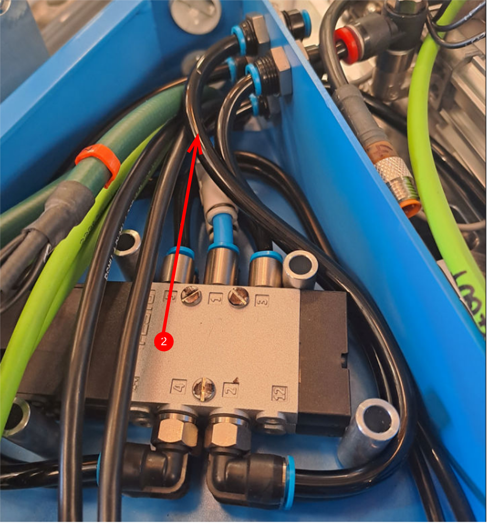
Étape 13 - Valve connections
1 Cut 4 off pieces of 6mm black airpipe @ 245mm and install in double slide connection boxes as shown, noting pipe routing
2 Cut 4 off pieces of 6mm black airpipe @ 205mm and install in double slide connection boxes as shown, noting pipe routing
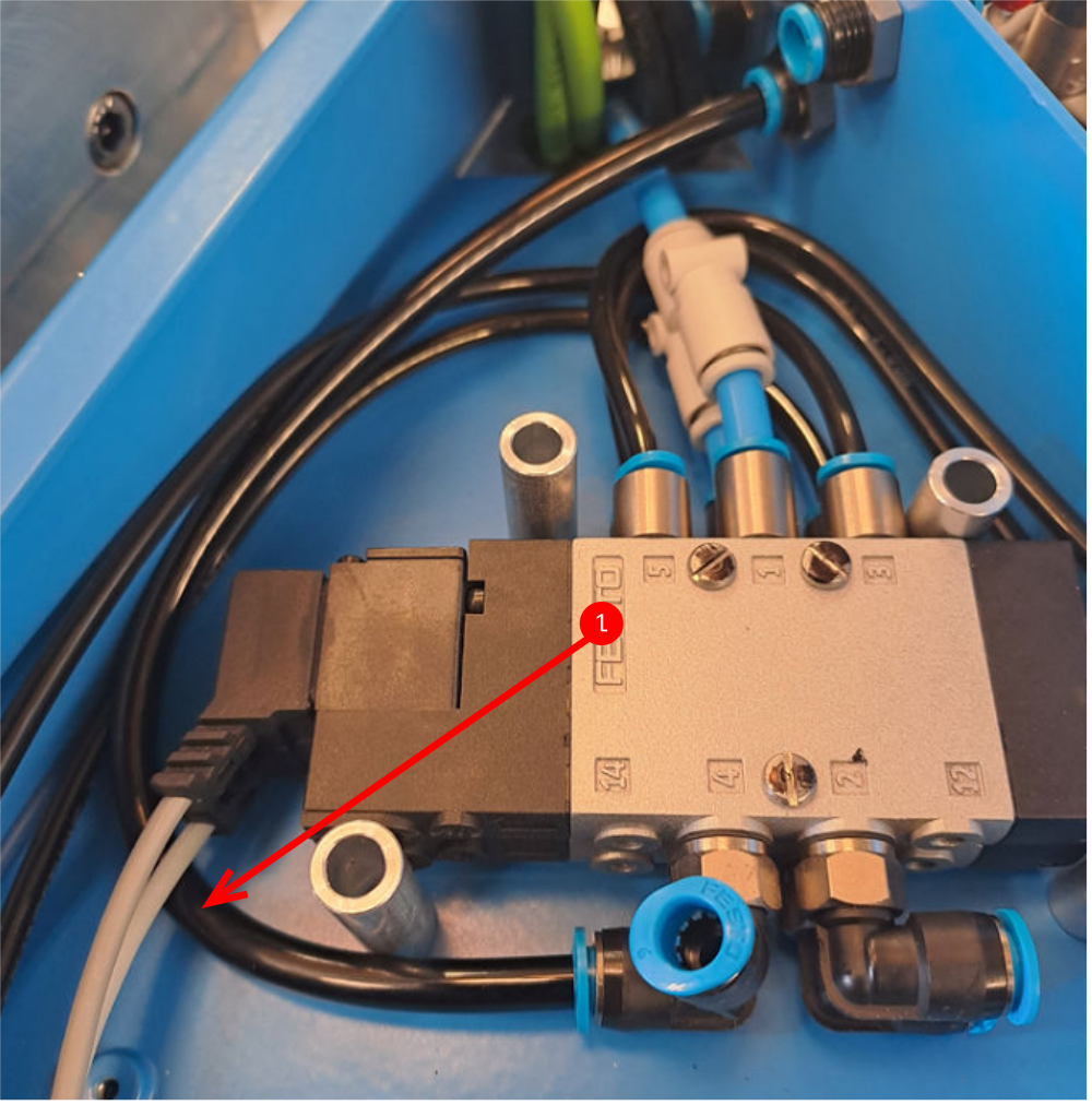
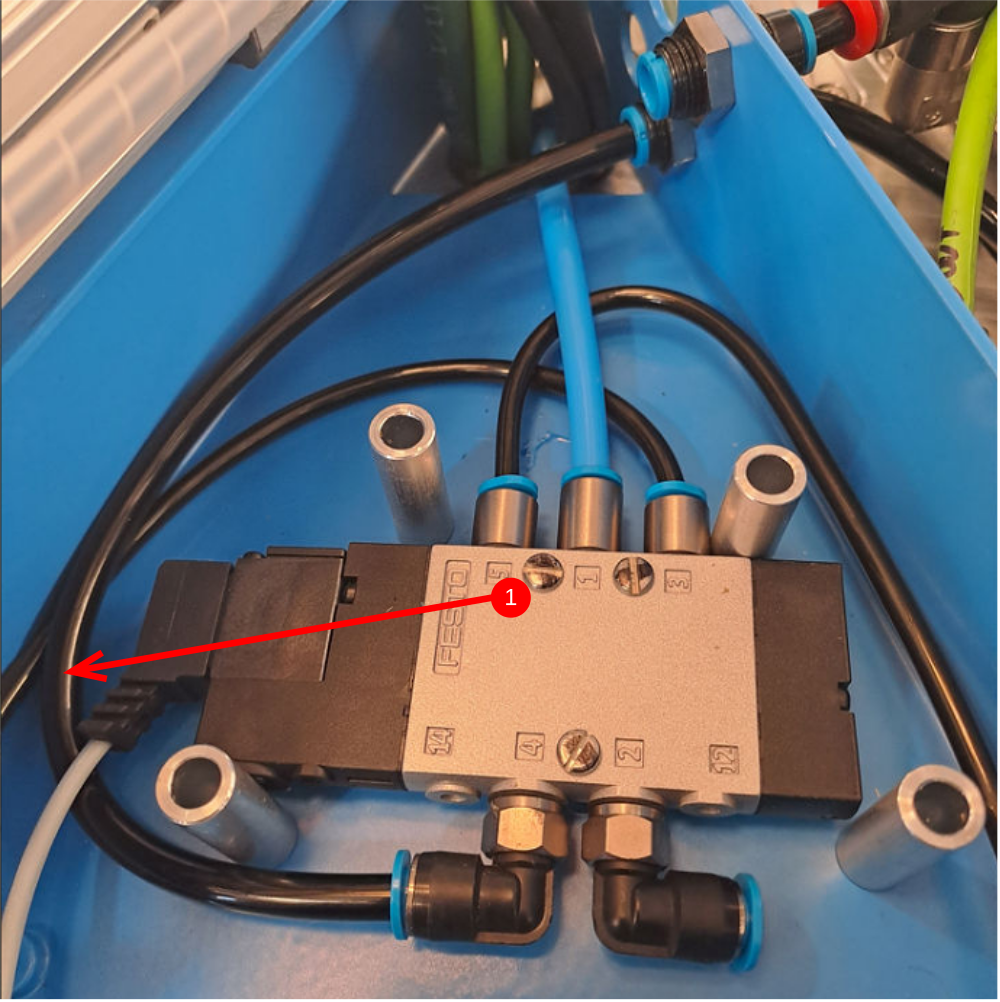
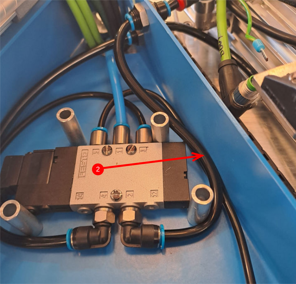
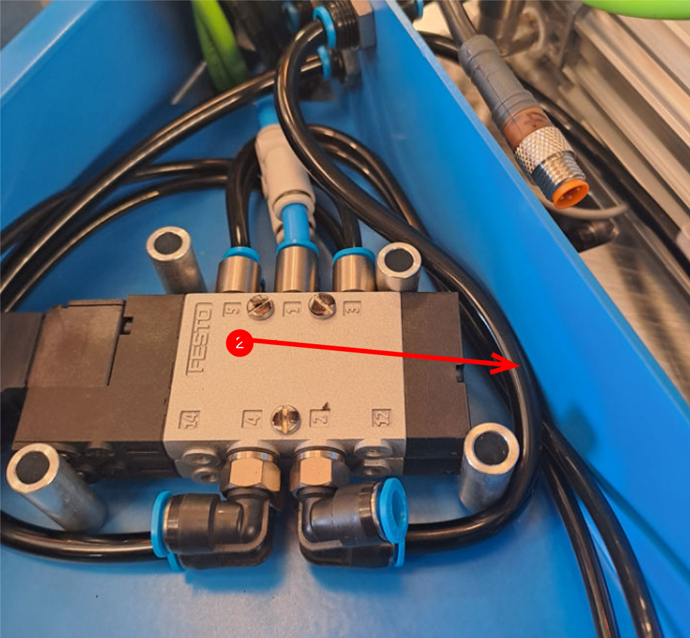
Étape 14 - Route single slide 300hz
1 Install 300hz cable from single slide spindle as shown (4 off)
2 Install 300hz cable from double slide spindle as shown (4 off)
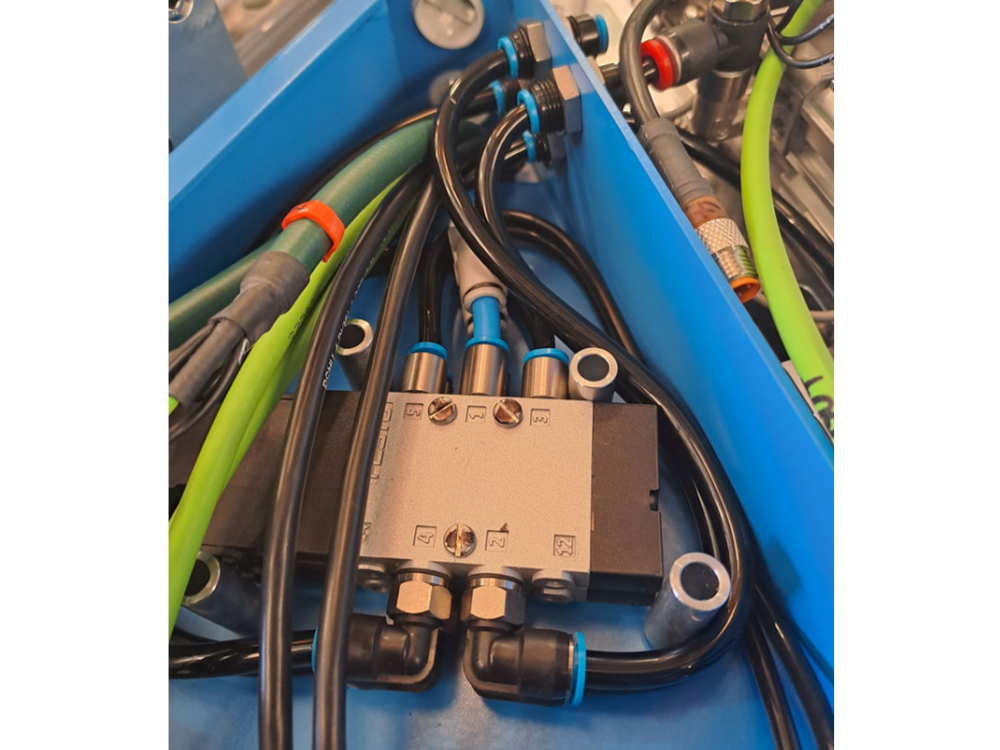
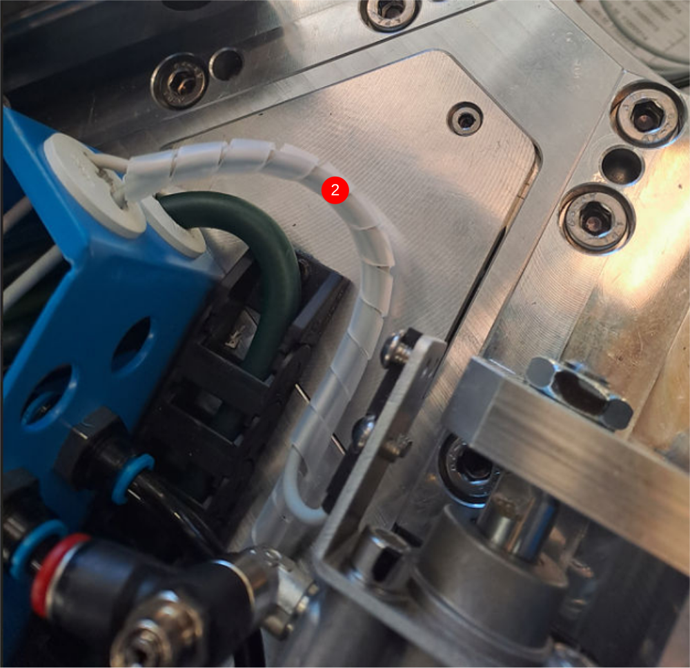
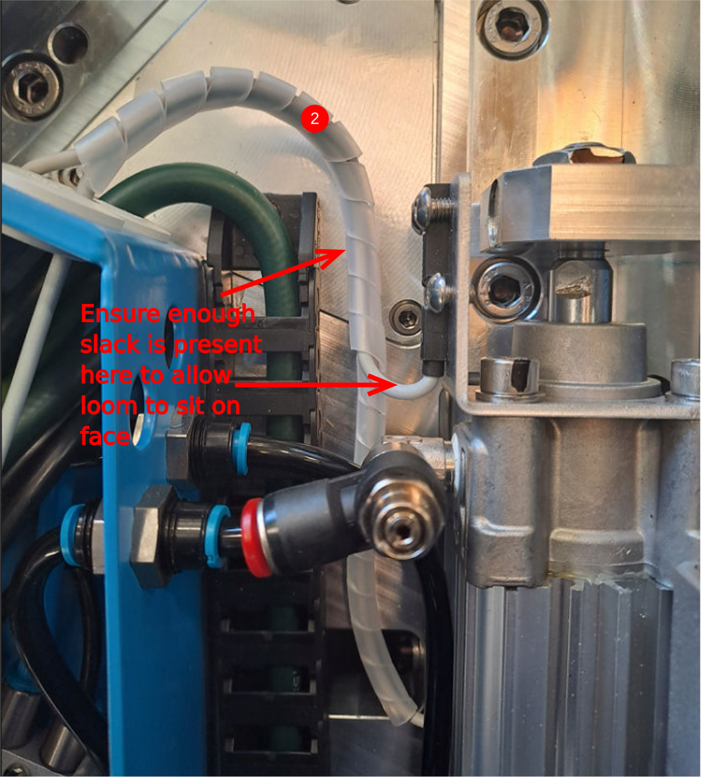
Étape 15 - Loom sensors
1 Loom with spiral wrap as shown sensors from double plunge assembly
2 Loom with spiral wrap as shown sensors from single plunge assembly
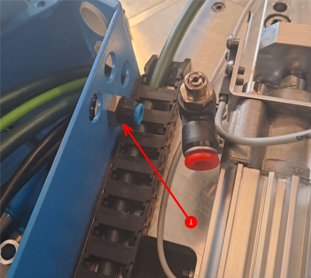
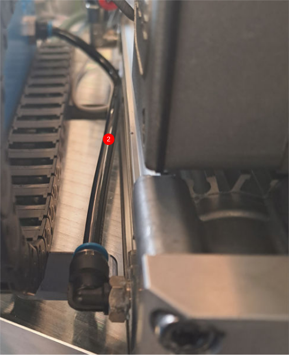
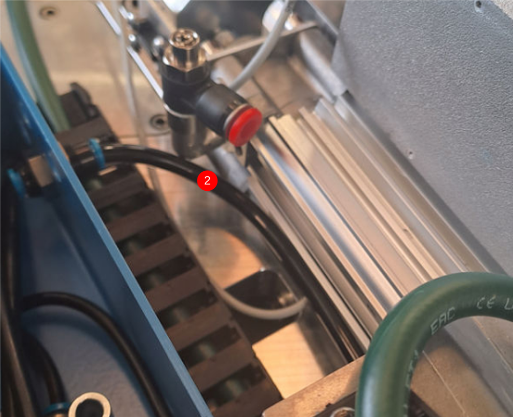
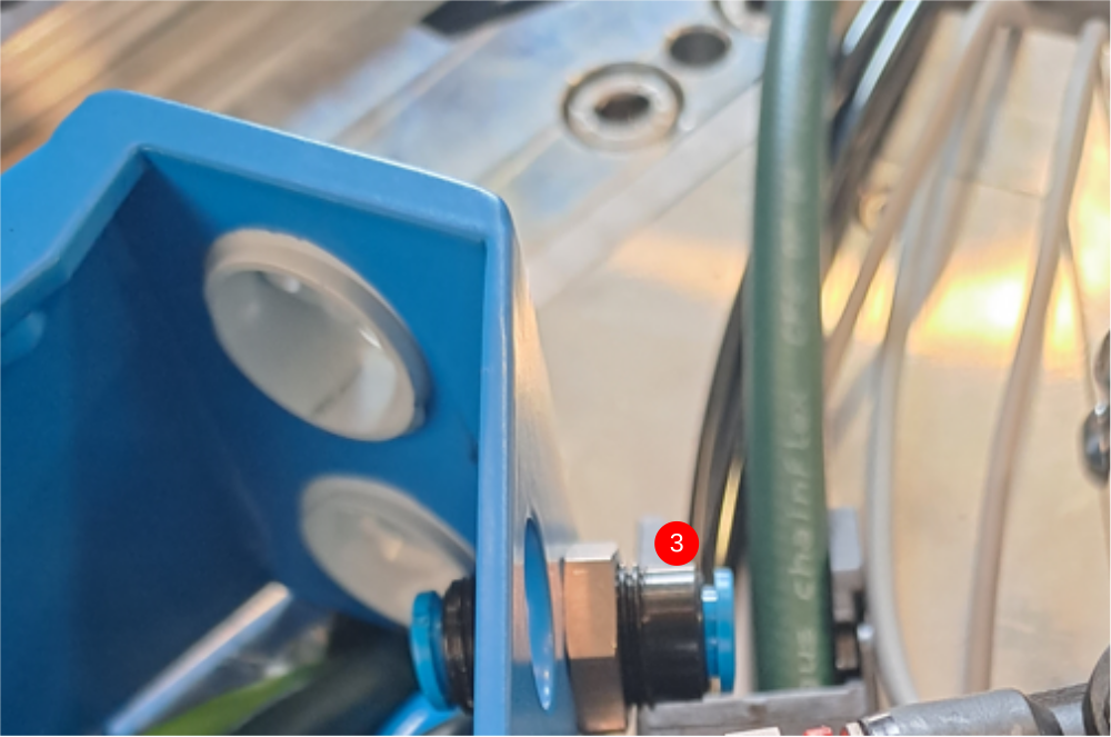
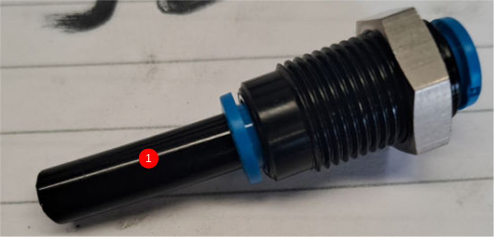
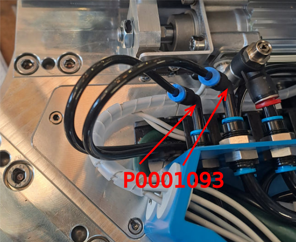
Étape 16 - Connect 4mm air pipes
Fit 2 off P0001093 stem elbows as shown then connect 4mm airpipes over length as shown to either connection ( these will be identified and tidied later on)
Repeat on remaining 3 double plunge connection boxes
Draft
 Français
 English
 Deutsch
 Español
 Italiano
 Português