Instructions to mount pre built assemblies to frame
Auteur  Gareth Green | Dernière modification 1/09/2025 par Gareth Green en cours de rédaction ⧼frevu-button-review-label⧽
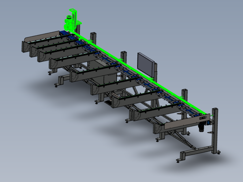
Instructions to mount pre built assemblies to frame
R0015266B_mount_completed_assemblies_Screenshot_2023-07-05_102048.png
en none 0 Draft
Vous avez entré un nom de page invalide, avec un ou plusieurs caractères suivants :
< > @ ~ : * € £ ` + = / \ | [ ] { } ; ? #
 Français
 English
 Deutsch
 Español
 Italiano
 Português