Details to install pneumatic and electrical loom

Difficulté
Difficile
Durée
8 heure(s)
Sommaire
- 1 Introduction
- 2 Étape 1 - Unless otherwise stated
- 3 Étape 2 - Fit Front Tray
- 4 Étape 3 - Valve bank identification
- 5 Étape 4 - Cabinet Feed Connections
- 6 Étape 5 - Rework fixing points
- 7 Étape 6 - Fit tie bases
- 8 Étape 7 - Fit rear Ethercat box and 240v socket
- 9 Étape 8 - Prepare Pipes and Cables
- 10 Étape 9 - Connections
- 11 Étape 10 - Loom Regulator pipes
- 12 Étape 11 - Loom Cables
- 13 Étape 12 - Y91 Eject reed switches
- 14 Étape 13 - Y91 Eject pneumatic connections
- 15 Étape 14 - Y80 Infeed top clamp
- 16 Commentaires
Introduction
This instruction is to incorporate assembly R0015033B Module F Wiring loom alongside this
See Electrical department for prepared components from above assembly
Tools Required
Pipe cutters
Pipe identification markers
Flush cutters
Parts Required
P0000010 6mm 1/8 elbow fitting x 6 P0000046 Fitting: 'Y' Adaptor 6mm x 6
P0000047 Bulkhead Elbow 6mm x 1
P0000159 Fitting: Stem Blanking Plug 6mm x 2
P0000160 Fitting: Flow Controller In Line 6mm x 2
P0000551 6mm inline Quick Exhaust Fitting x 3
P0001030 Fitting: SMC 6mm Equal Tee x 1
P0001008 regulator x 3
P0001009 Regulator nut x 3
P0001107 Fitting 12mm equal tee x 1
P0001166 12mm tube to tube elbow x 1
Étape 1 - Unless otherwise stated
All bolts to have Loctite 243 adhesive applied unless otherwise stated
All Threaded Pneumatic connections to have Loctite 570 applied
All bolts to be pen marked once adhesive applied and correct tension added

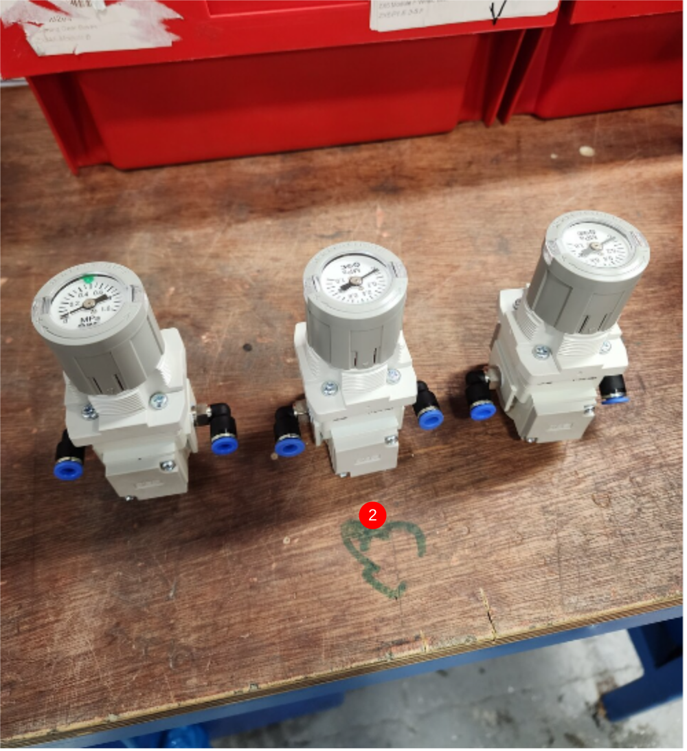
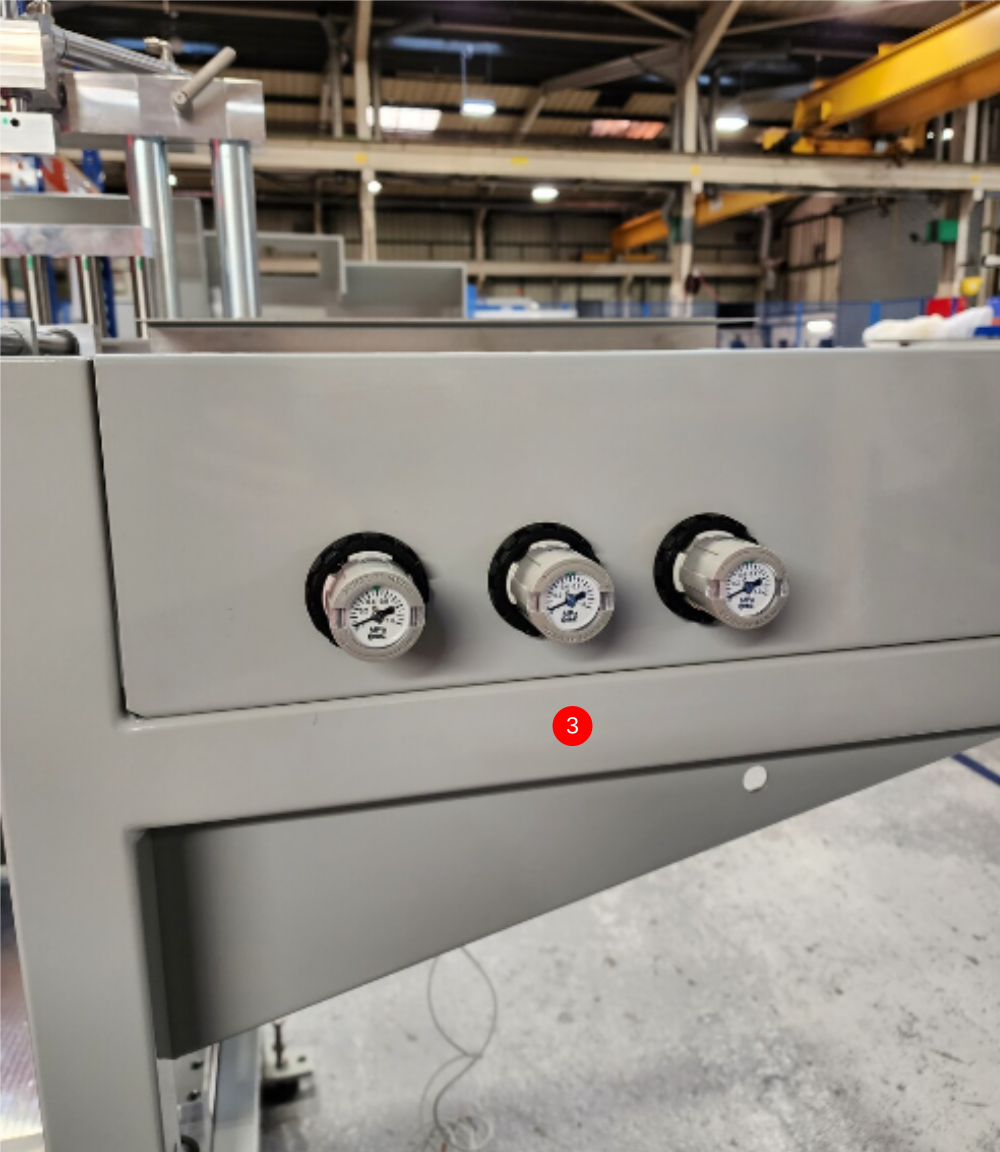
Étape 2 - Fit Front Tray
1 Fit front tray using 3 off M6 x 12 socket caps and 3 off penny washers
Ensure tray is fitted flush to frame on external edges
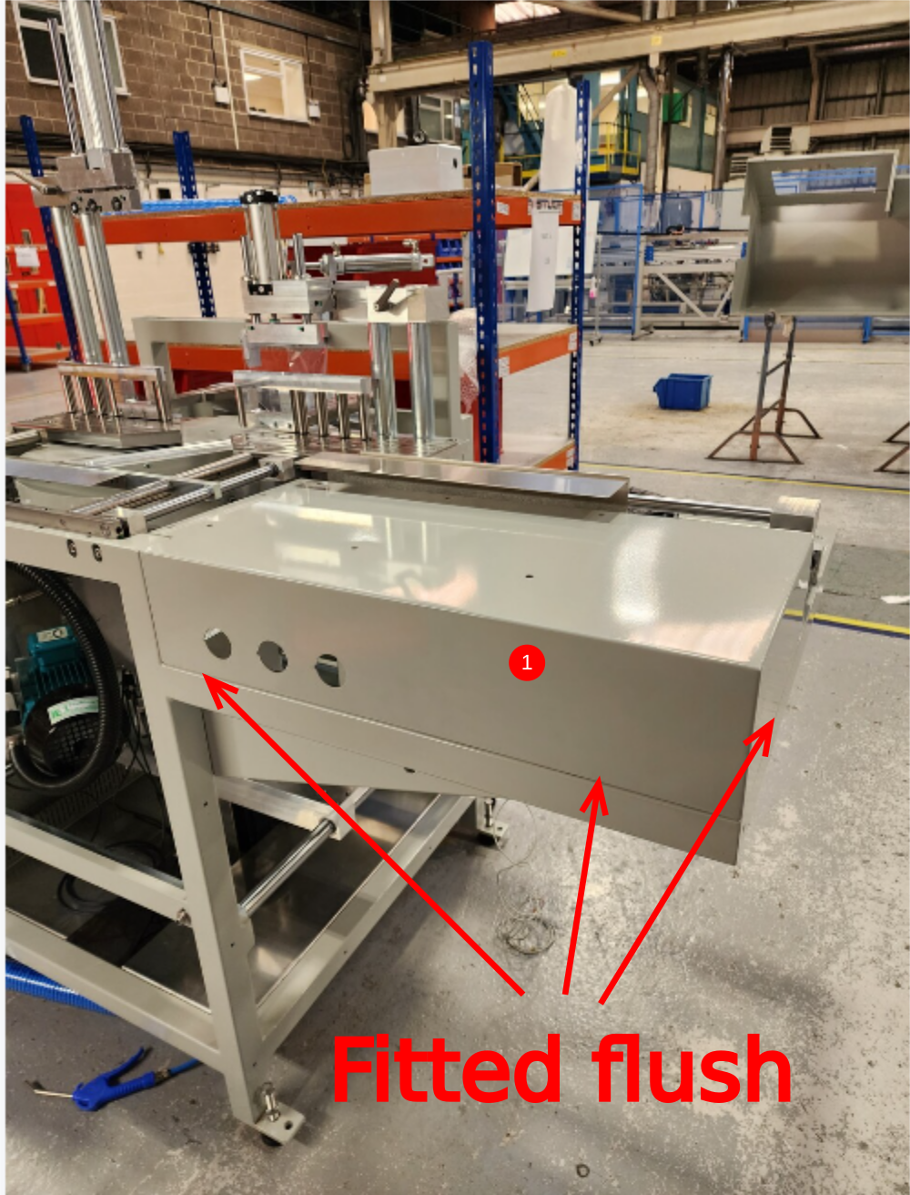
2 Assemble 3 off P0001008 regulators with 6 off P0000010 elbows as shown
3 Fit regulators to tray , ensuring all orientated the same and correct way
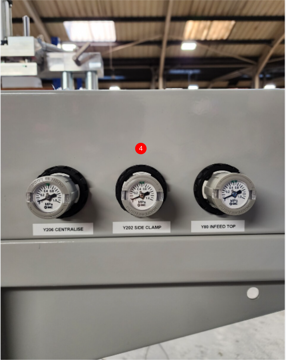
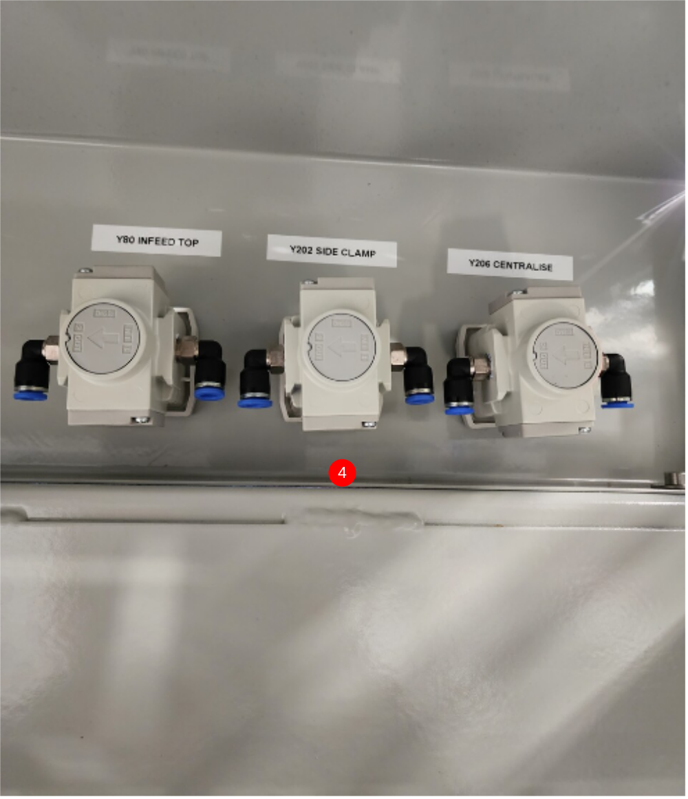
4 Add identification labels printed from dyno machine to regulators front and rear as follows
Y206 Centralise
Y202 Side clamp
Y80 Infeed Top clamp
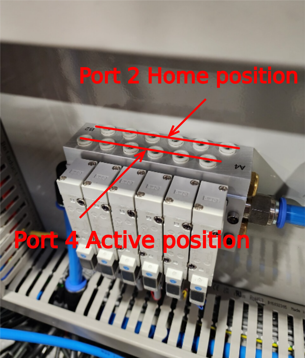
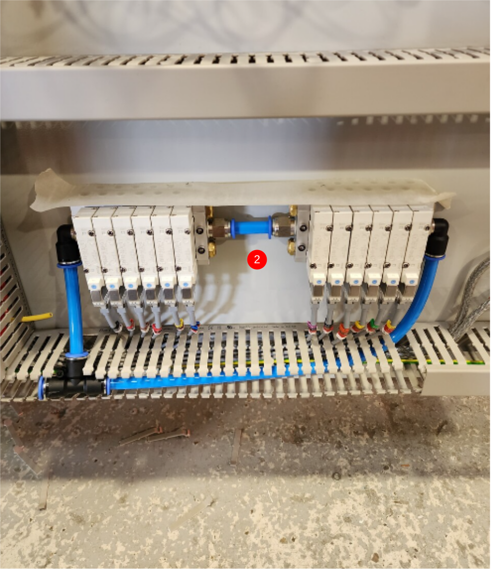
Étape 3 - Valve bank identification
2 Row is home position
4 Row is active position

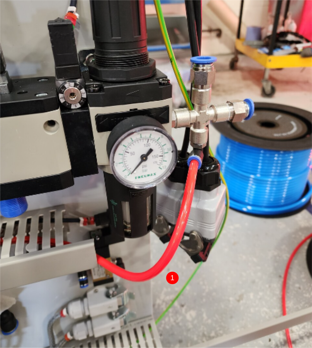
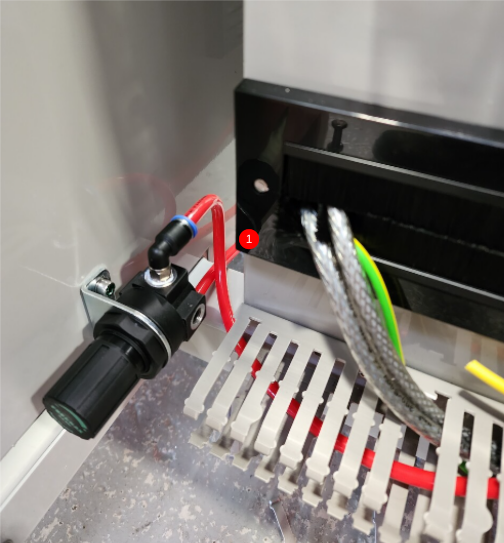
Étape 4 - Cabinet Feed Connections
1 Connect 8mm Red pipe to air gun regulator .From main air service unit through trunking to regulator
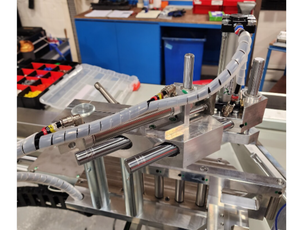
2 Connect 12mm pipe as shown


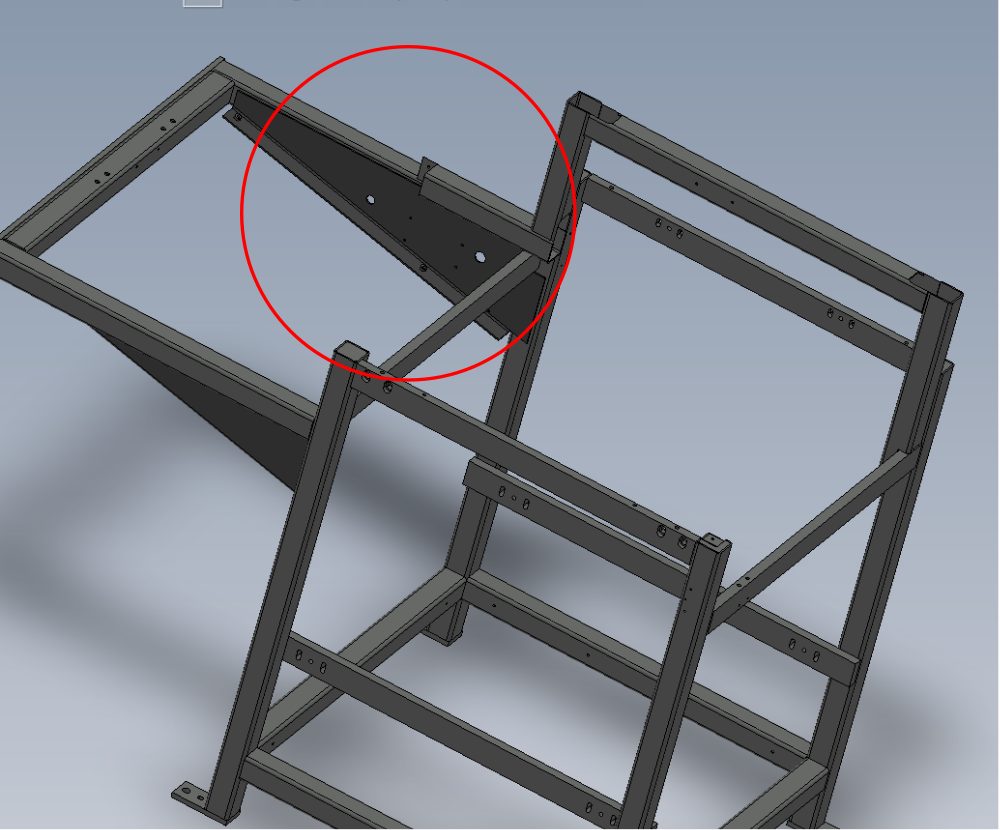
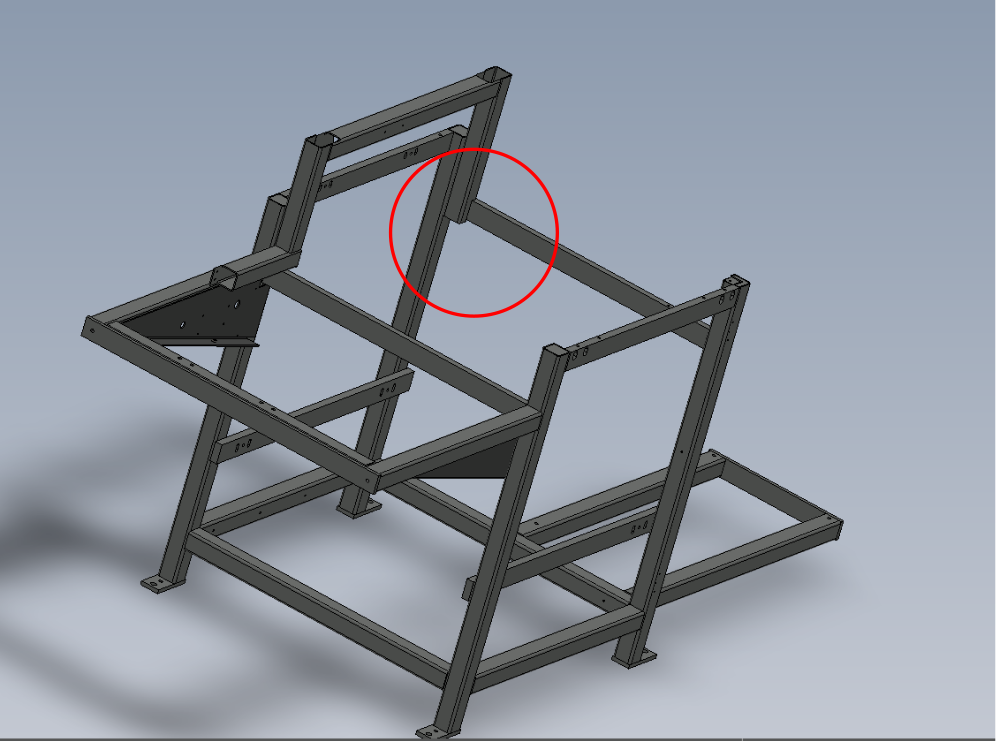
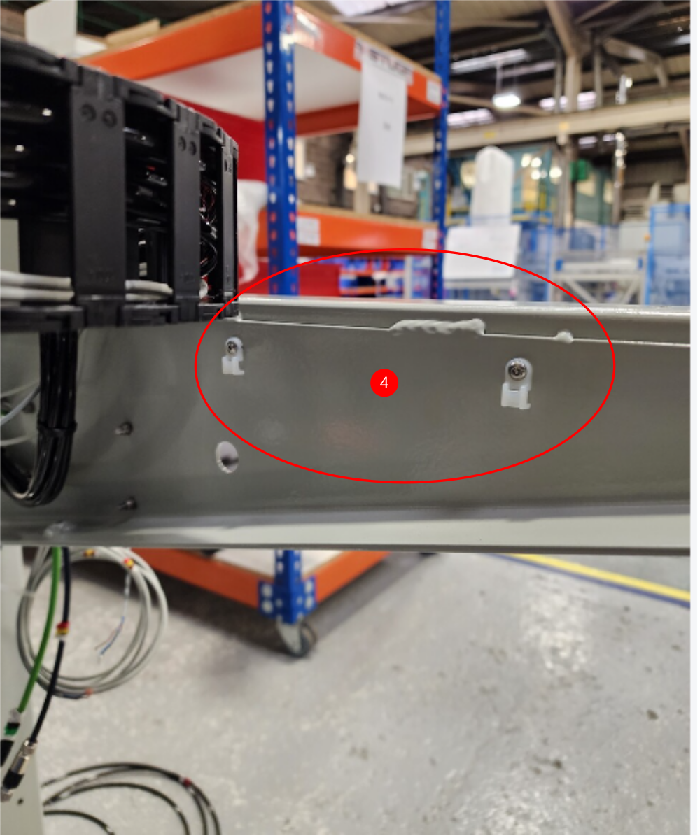
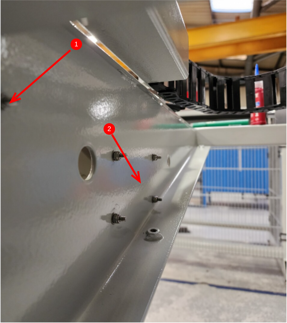
Étape 5 - Rework fixing points
Additional holes added for cable tie bases .
ECR Raised 14/12 /23 to capture. Until processed rework parts at production
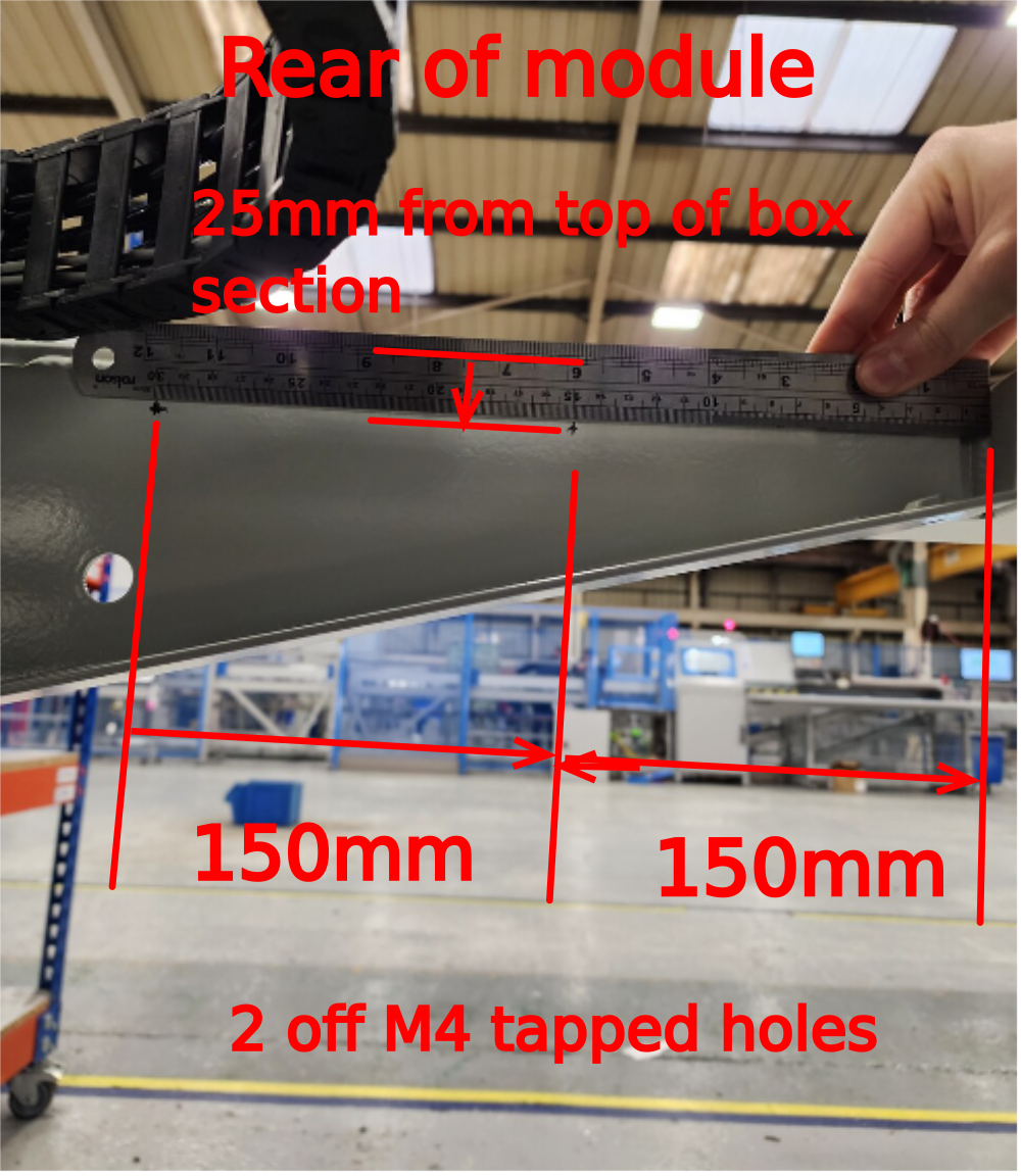
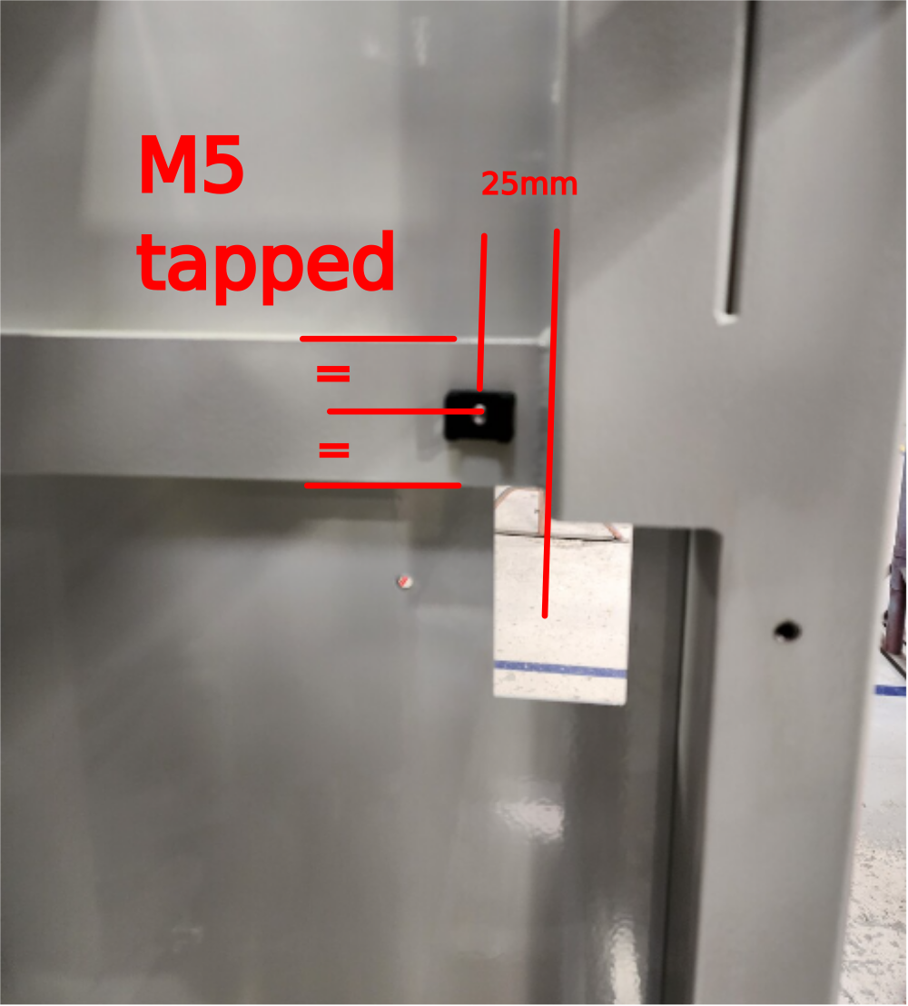
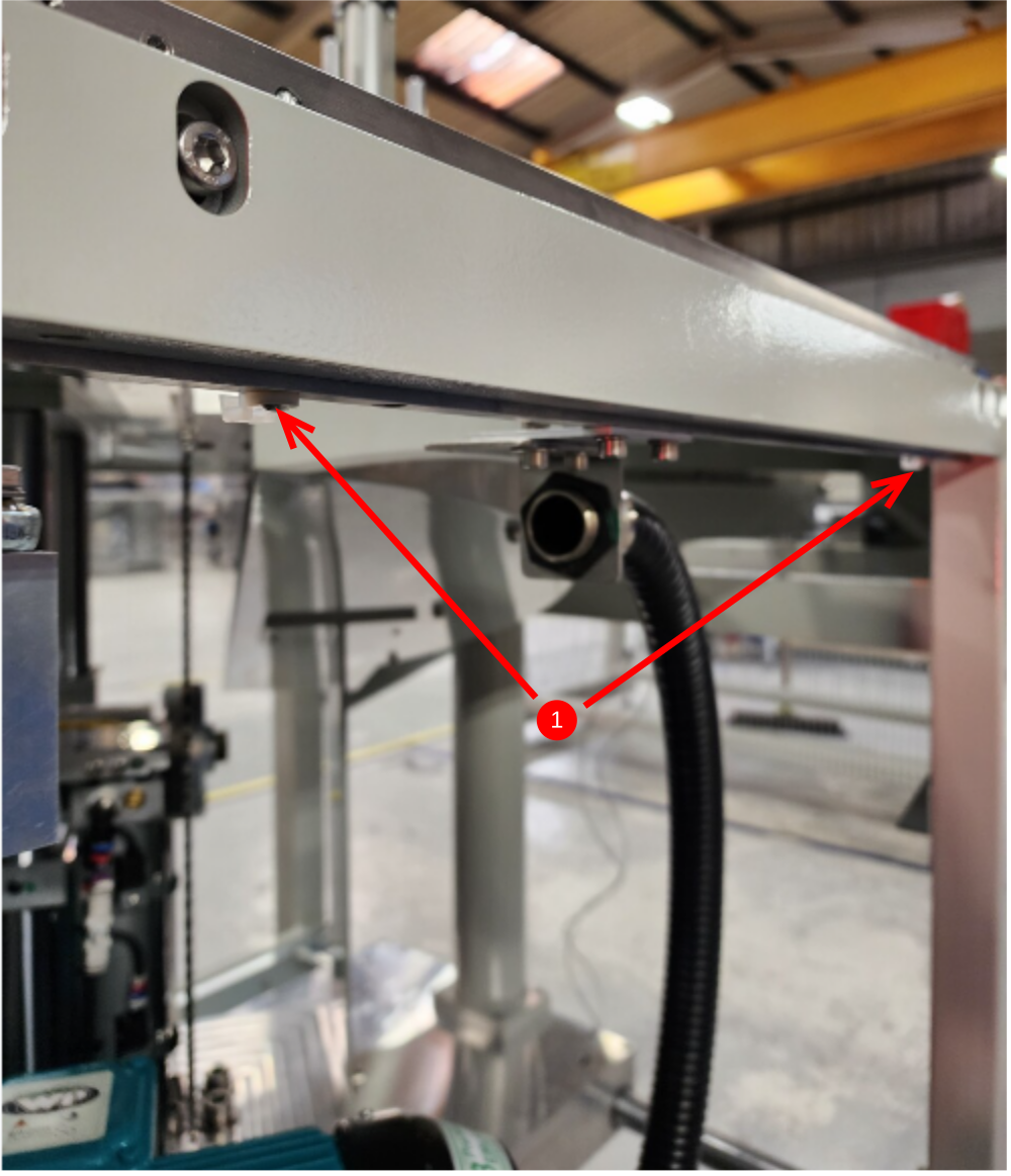
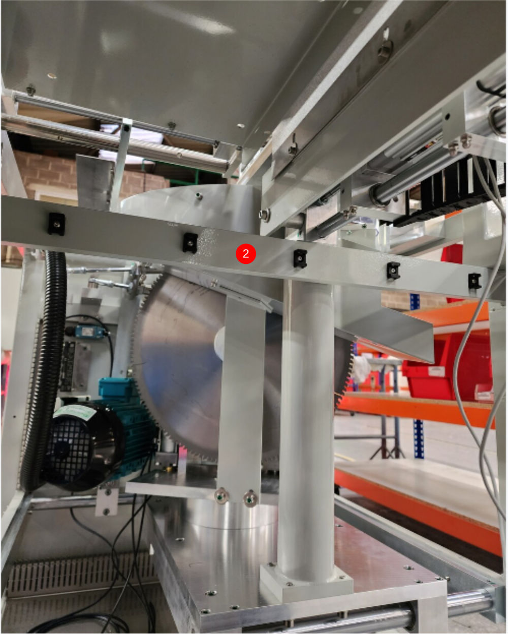
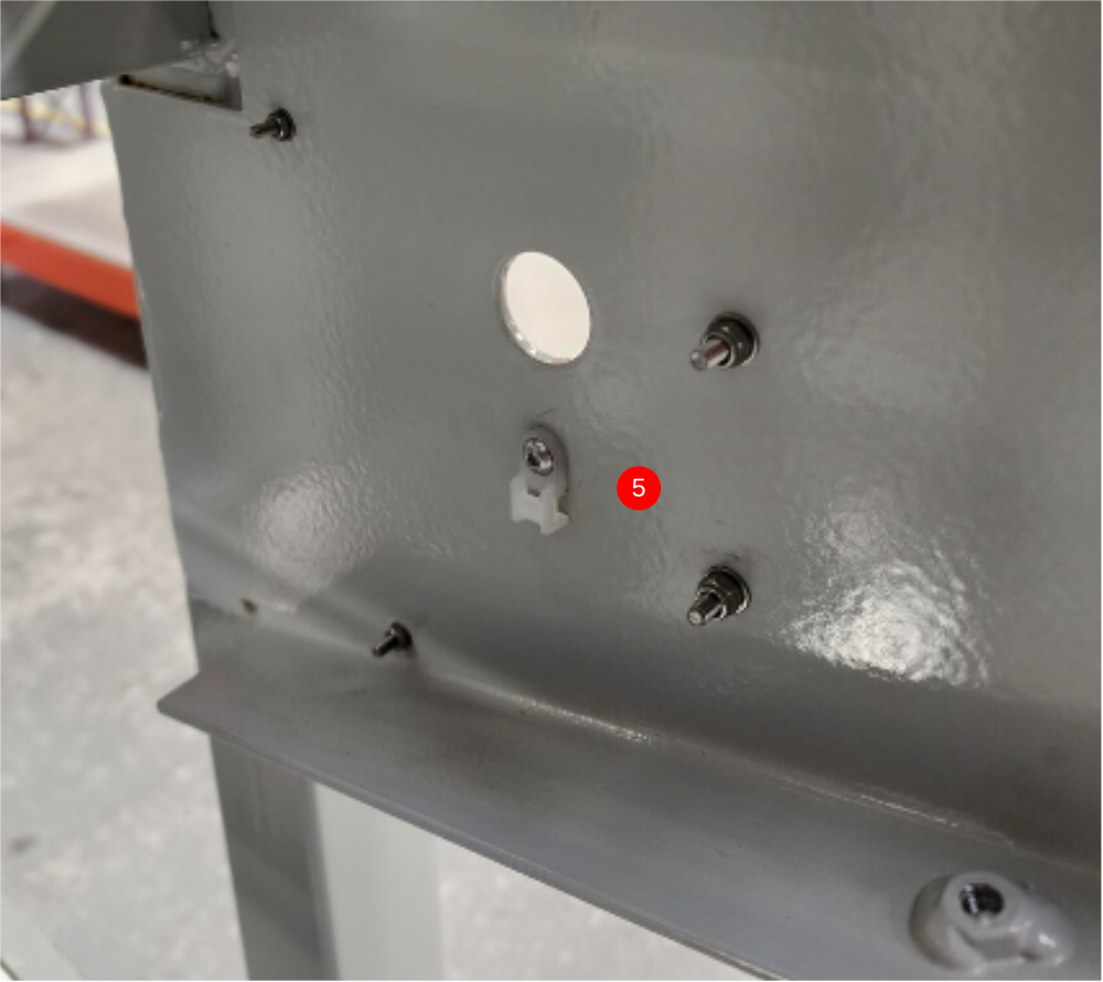
Étape 6 - Fit tie bases
1 Fit 2 off M4 tie base as shown using M4 x 6 button sockets. Ensure to orientate as shown
2 Fit 5 off M6 tie base as shown. Use M5x10 button sockets to fix
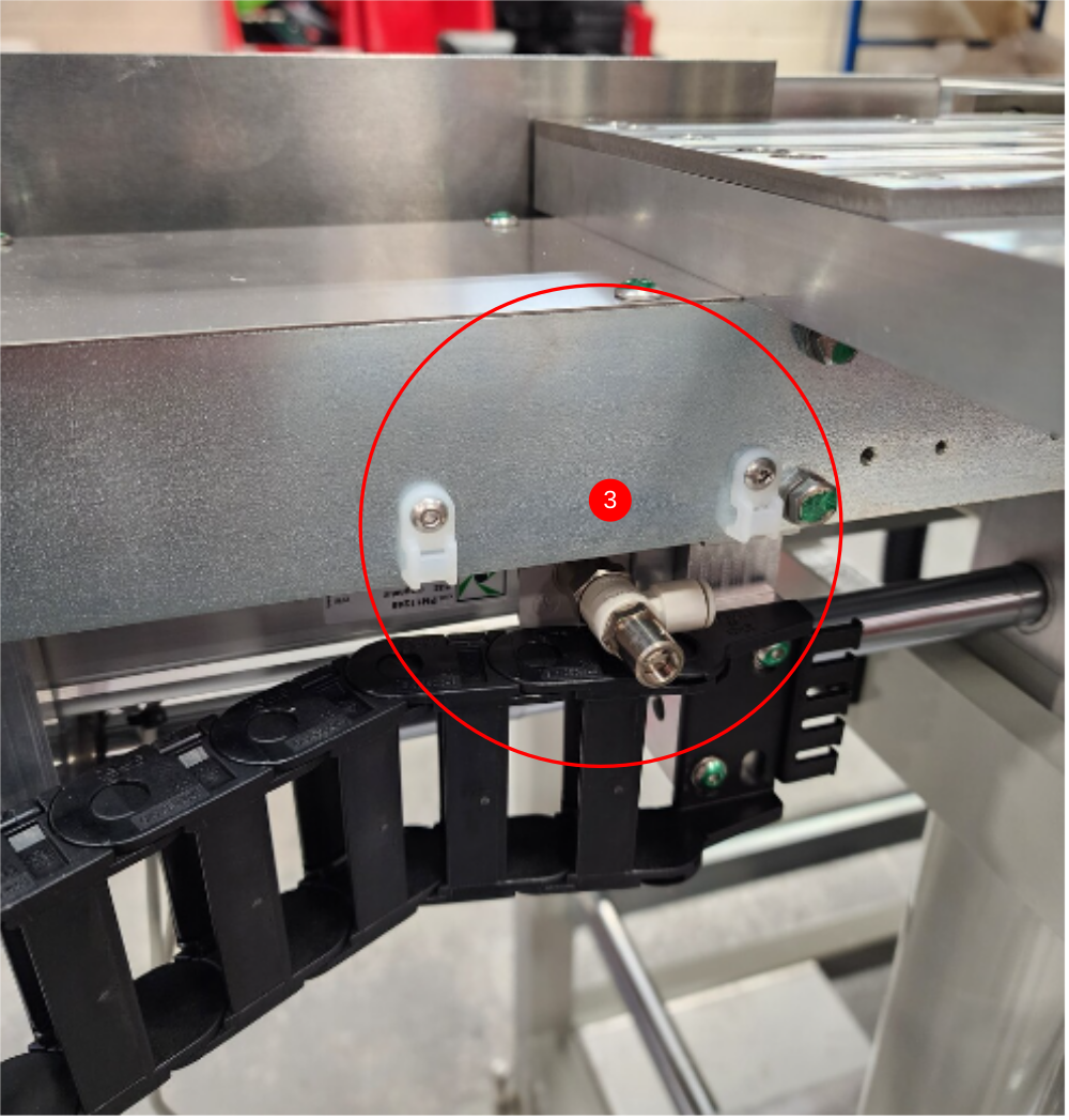
3 Fit 2 off M4 tie bases to eject using 2 off M4 x 6 button sockets
4 Fit 2 off M4 tie bases to eject using 2 off M4 x 6 button sockets
5 Fit 1 off M4 tie bases to eject using 1 off M4 x 6 button socket
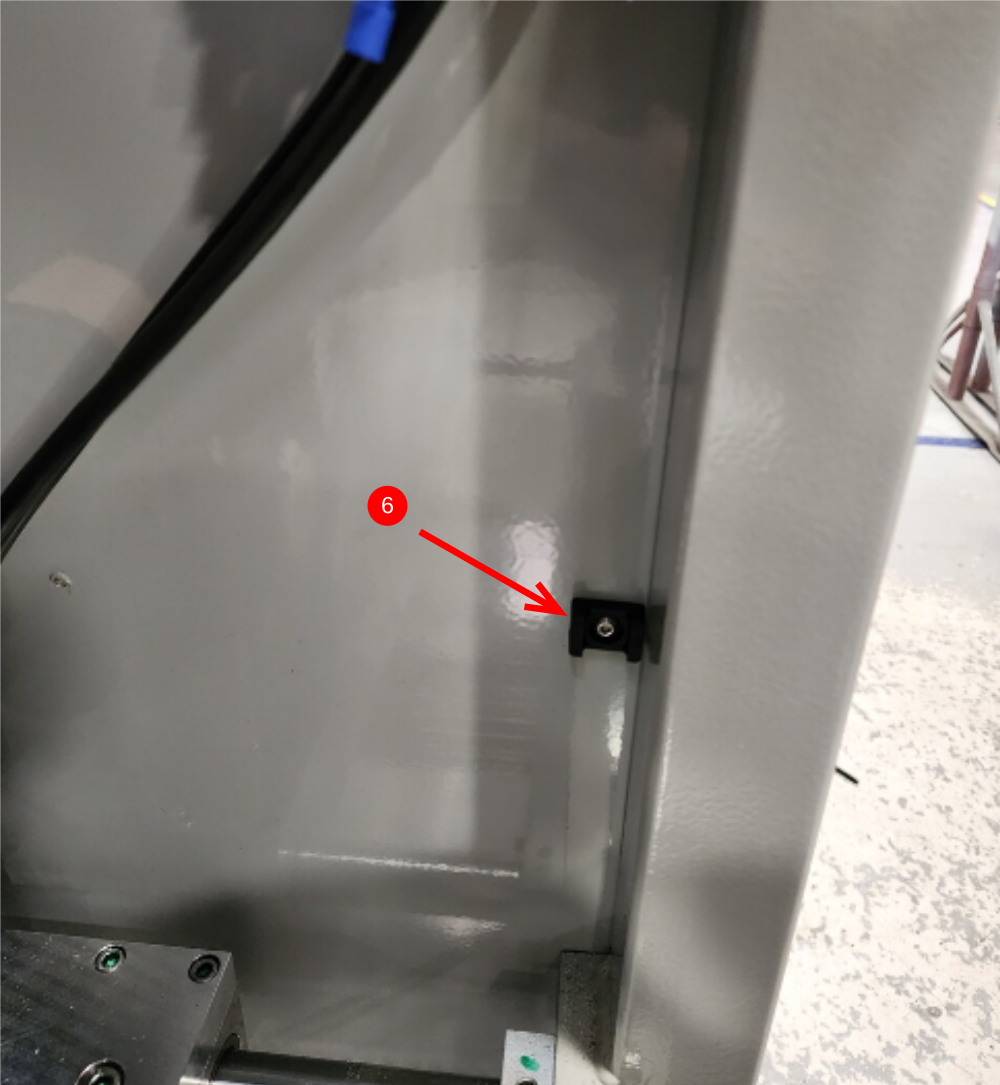
6 Fit 1 off M6 cable tie base using M5 x 10 button socket
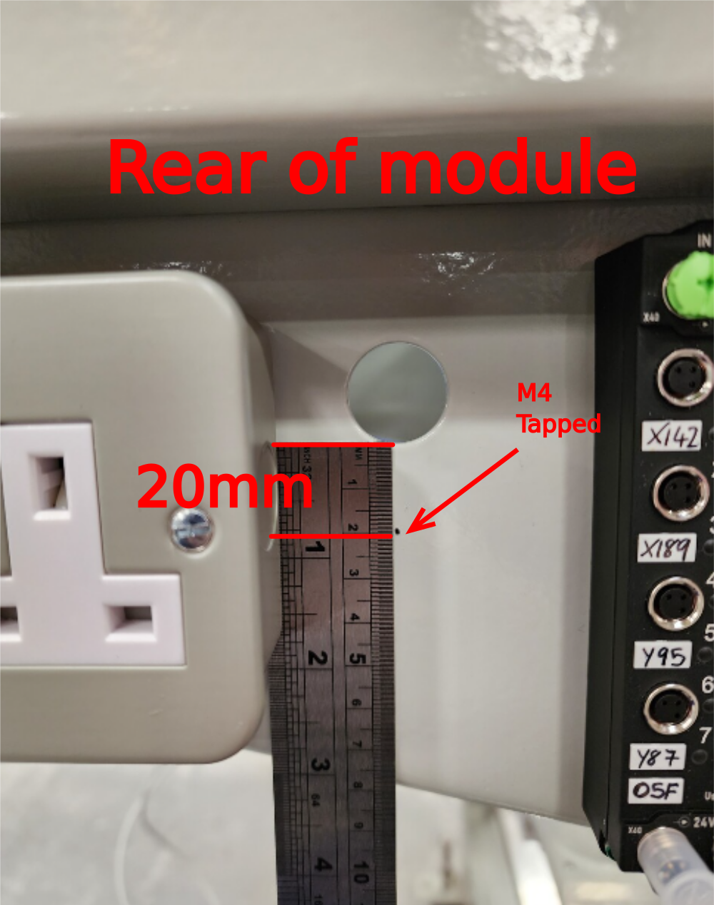
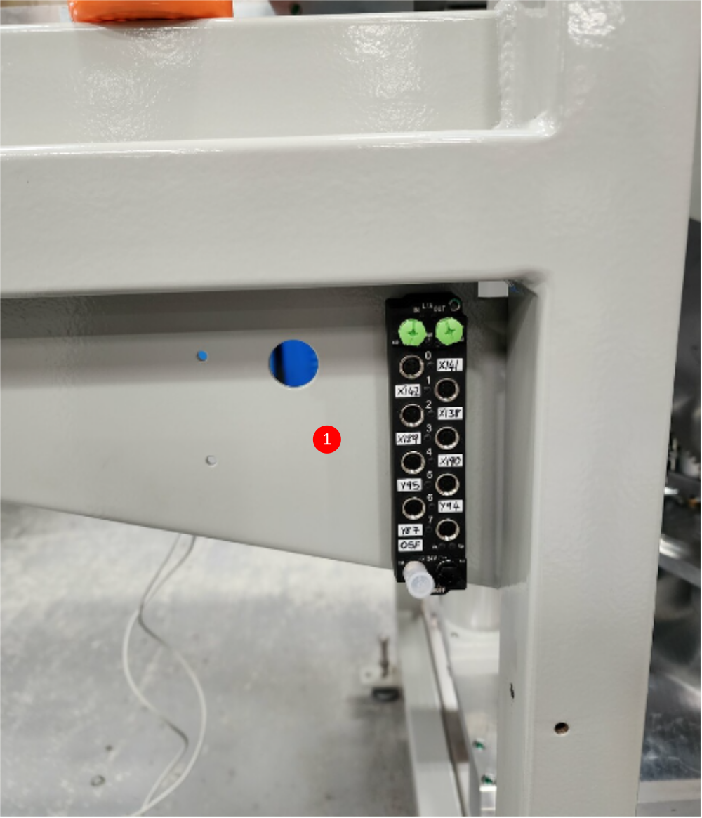
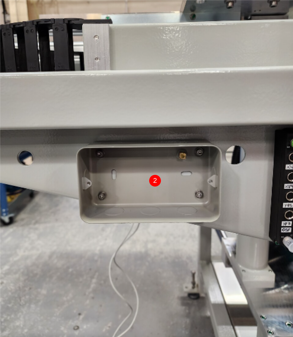
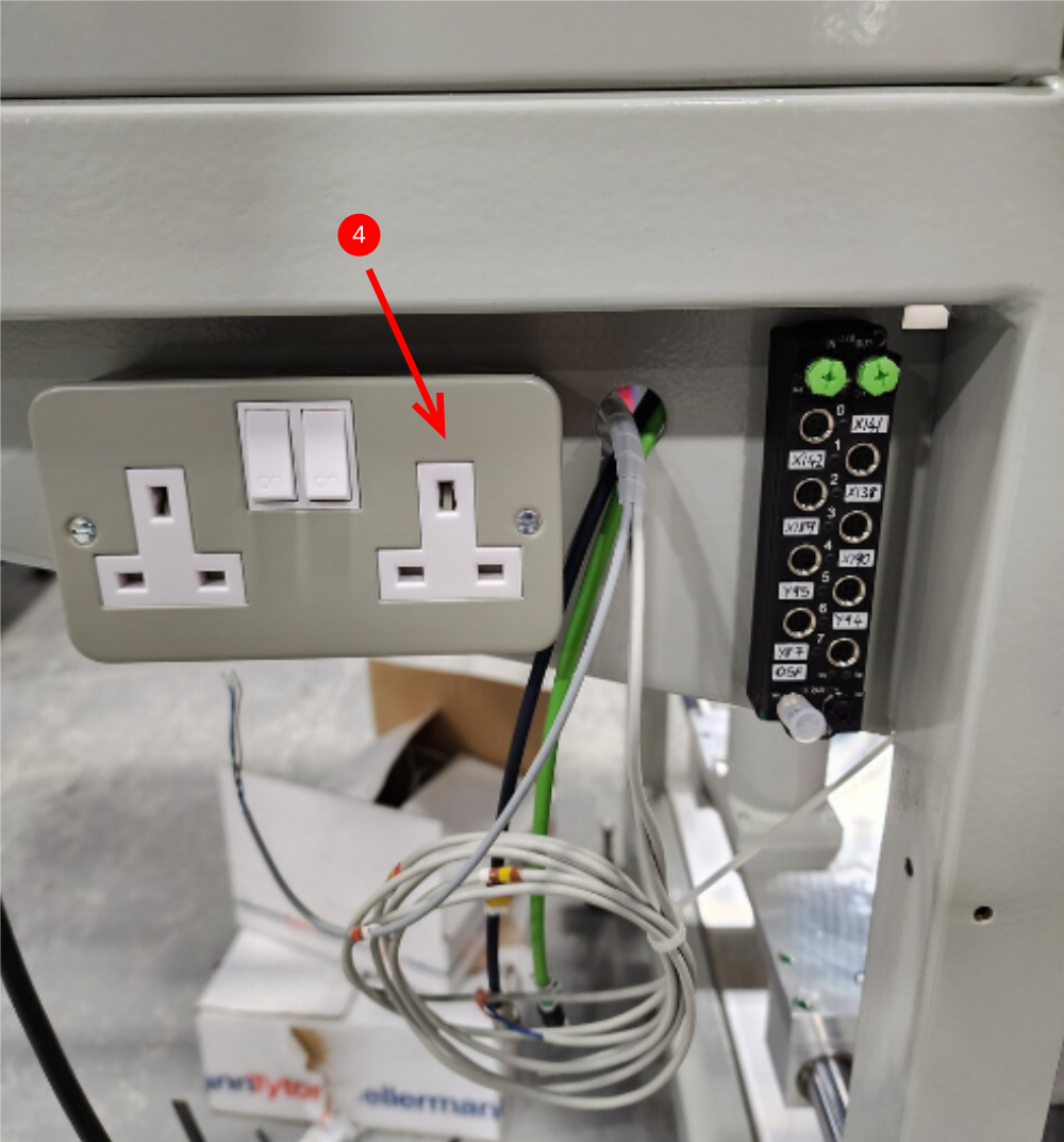
Étape 7 - Fit rear Ethercat box and 240v socket
1 Fit ethercat box as shown using 2 off M3 x 25 pan heads. Fit 2 off M3 A Form washers and 2 off M3 nuts behind
2 Fit 240v socket using 4 off M4 x 12 socket caps and 4 off A Form washers . Fit 4 off M4 A Form washers and 4 off M4 nyloc nuts behind
3 Refit front cover to 240v connection box
Étape 8 - Prepare Pipes and Cables
1 Cut 6 lengths of 6mm black pipe at 5 meter long .
2 Use cables EC06F and 25F from loom box

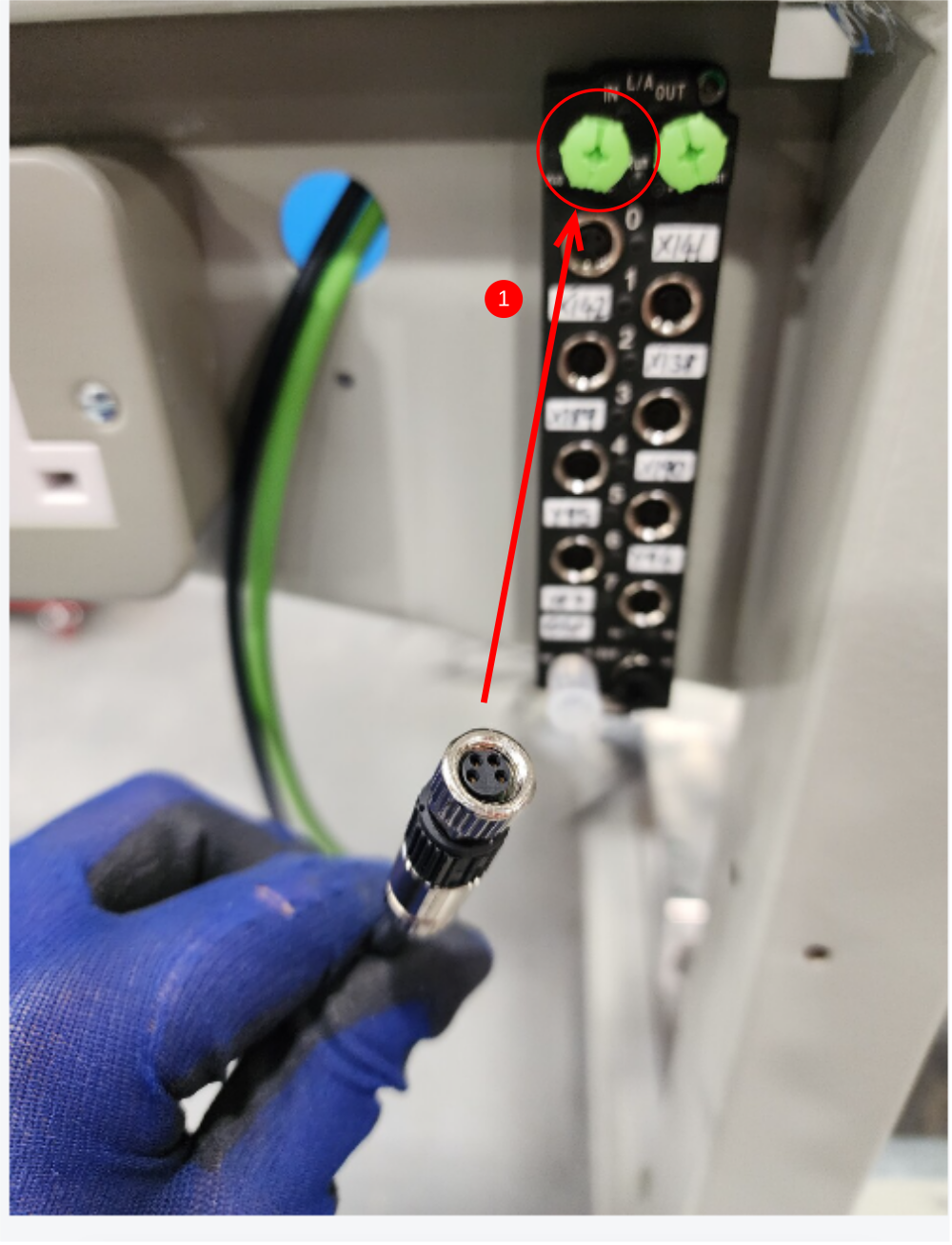
Étape 9 - Connections
1 Connect EC06f to in port of shown Ethercat box
2 Connect 25f to in port of shown Ethercat box and tidy loom with cable ties
3 Leave slack here for regulator connections

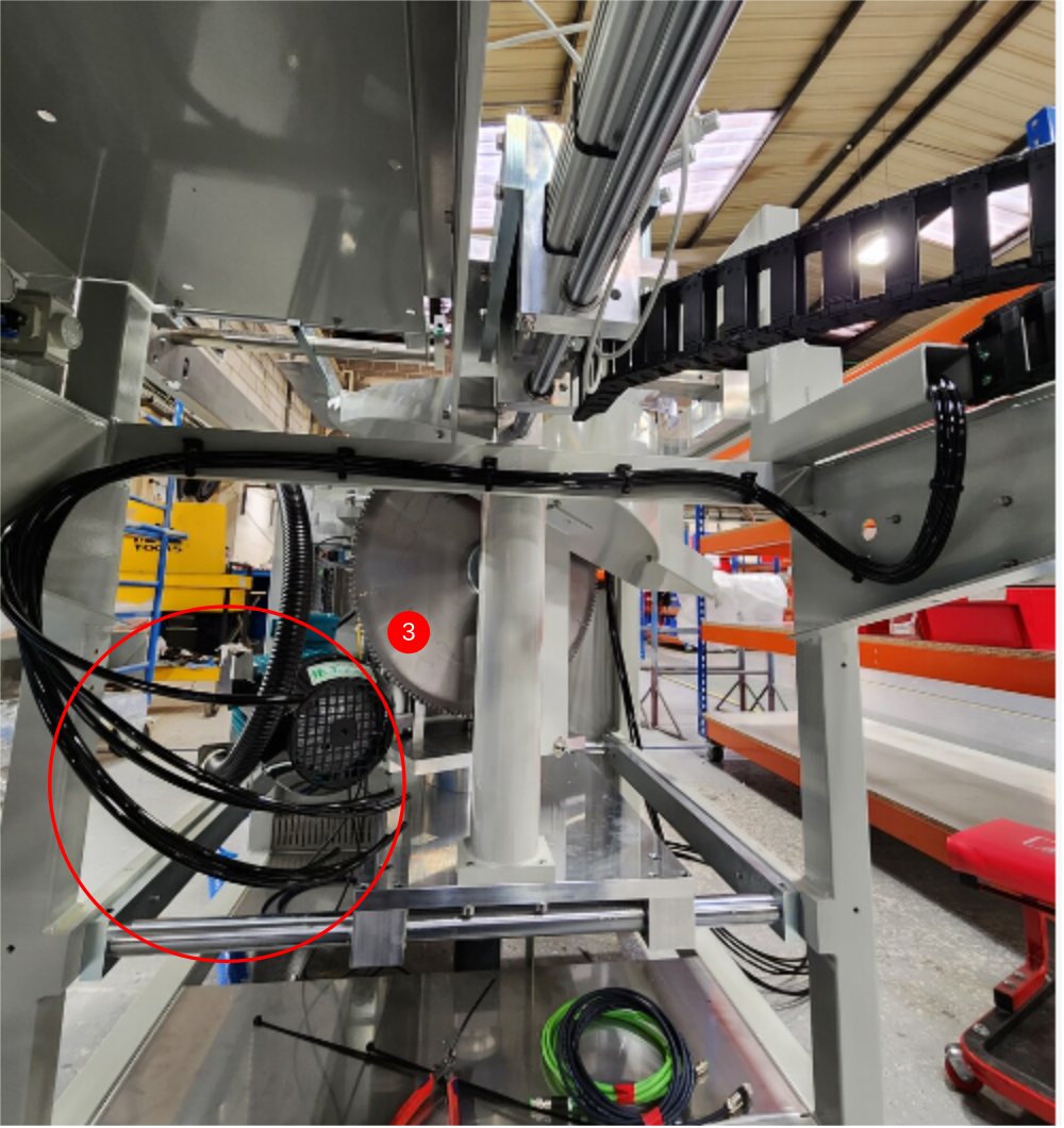
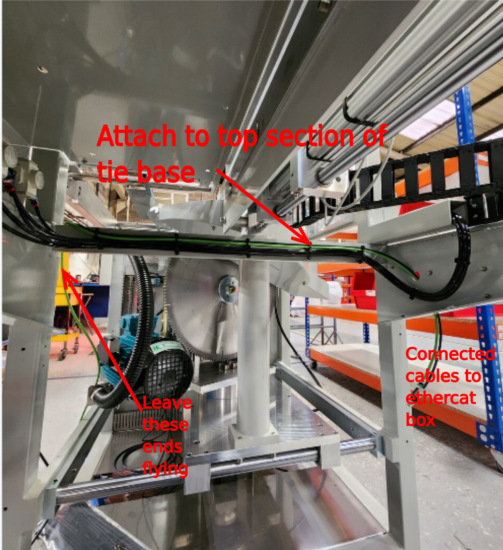
Étape 10 - Loom Regulator pipes
1 Loom across and attach 6 off 6mm black pipes to lower tab of tie bases.
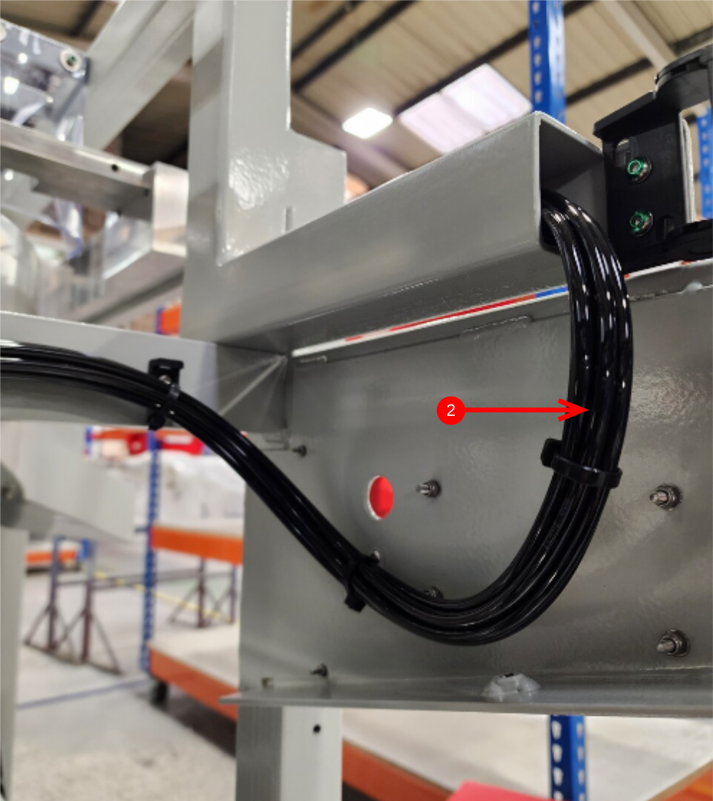
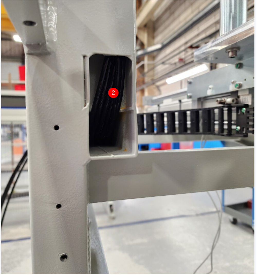
2 Route pipes through area shown
3 Exit pipes at this point
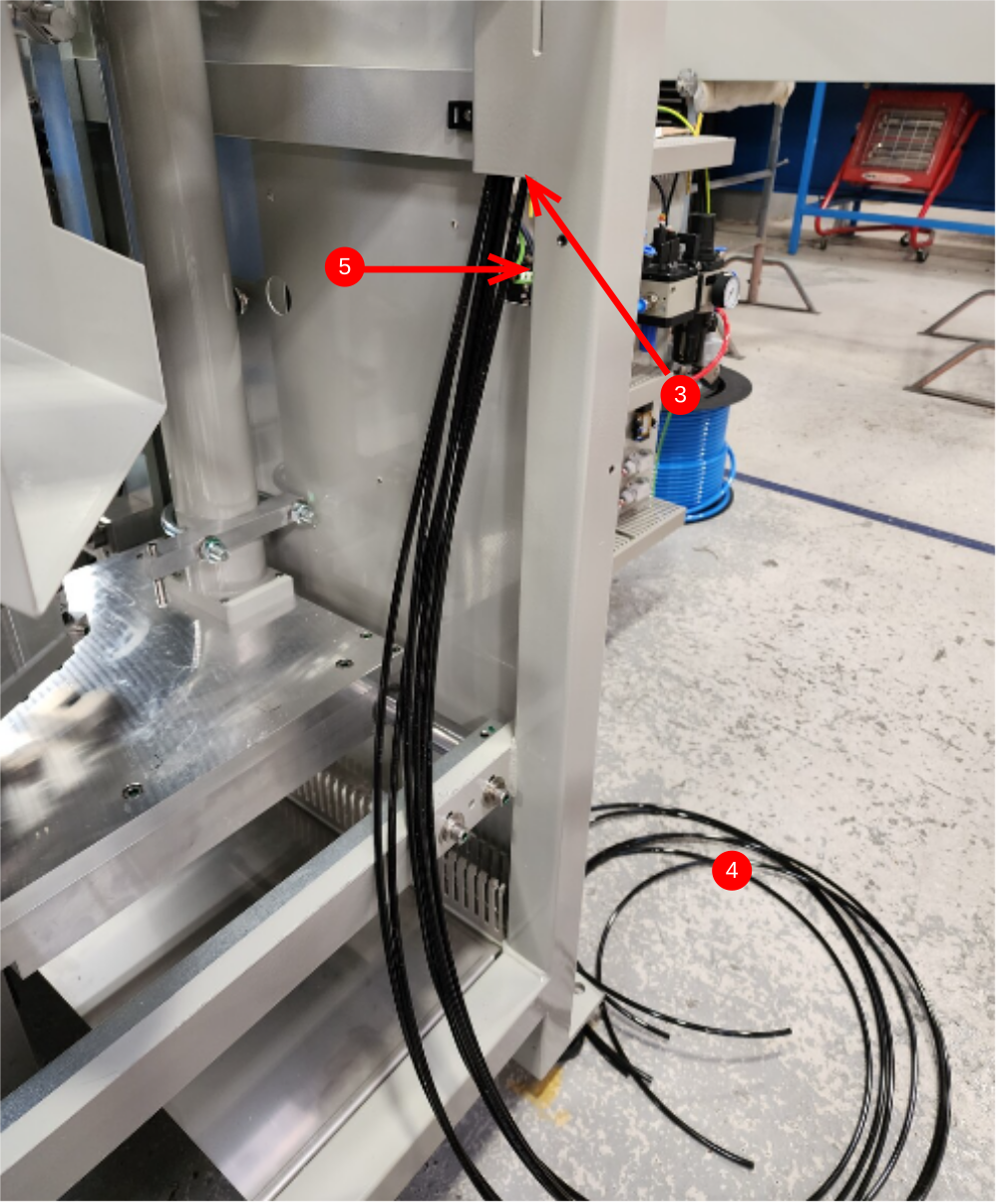
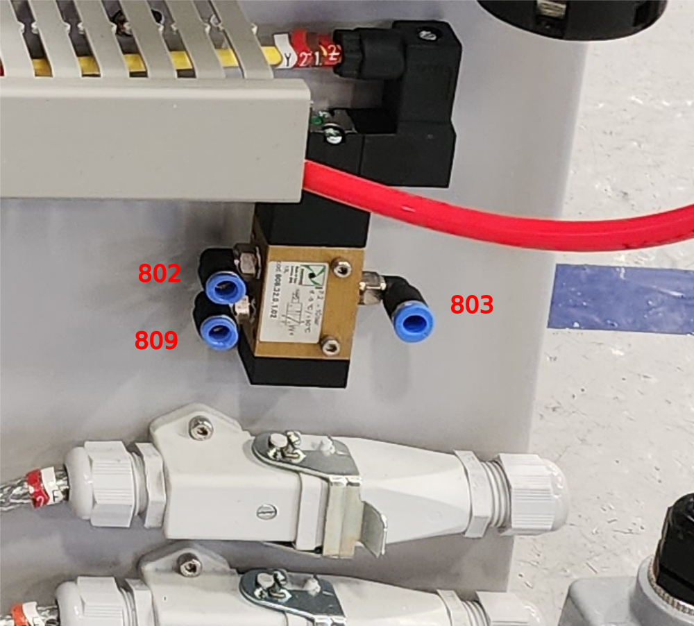
4 Identify pipes using airline to blow through. Use numbers 2069,2029,809,802,2022 and 2062.
5 Exit 2069,2029,809 and 802 through cutout. Leave 2022 and 2062 as is
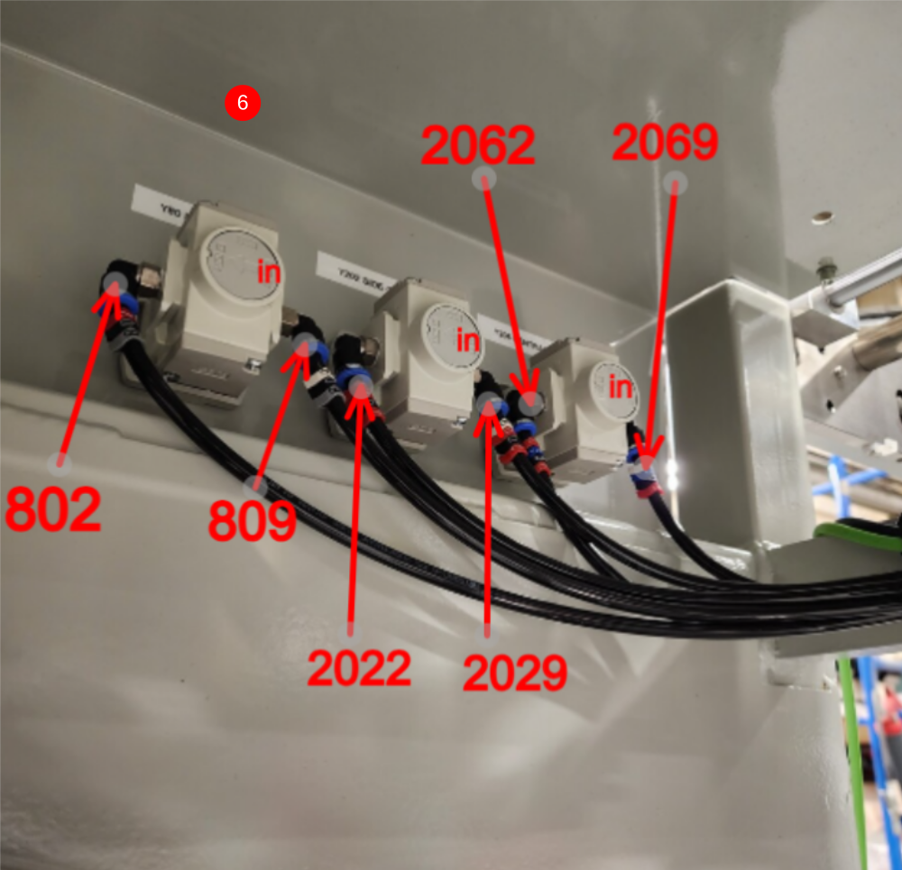
6 Connect Regulators as shown
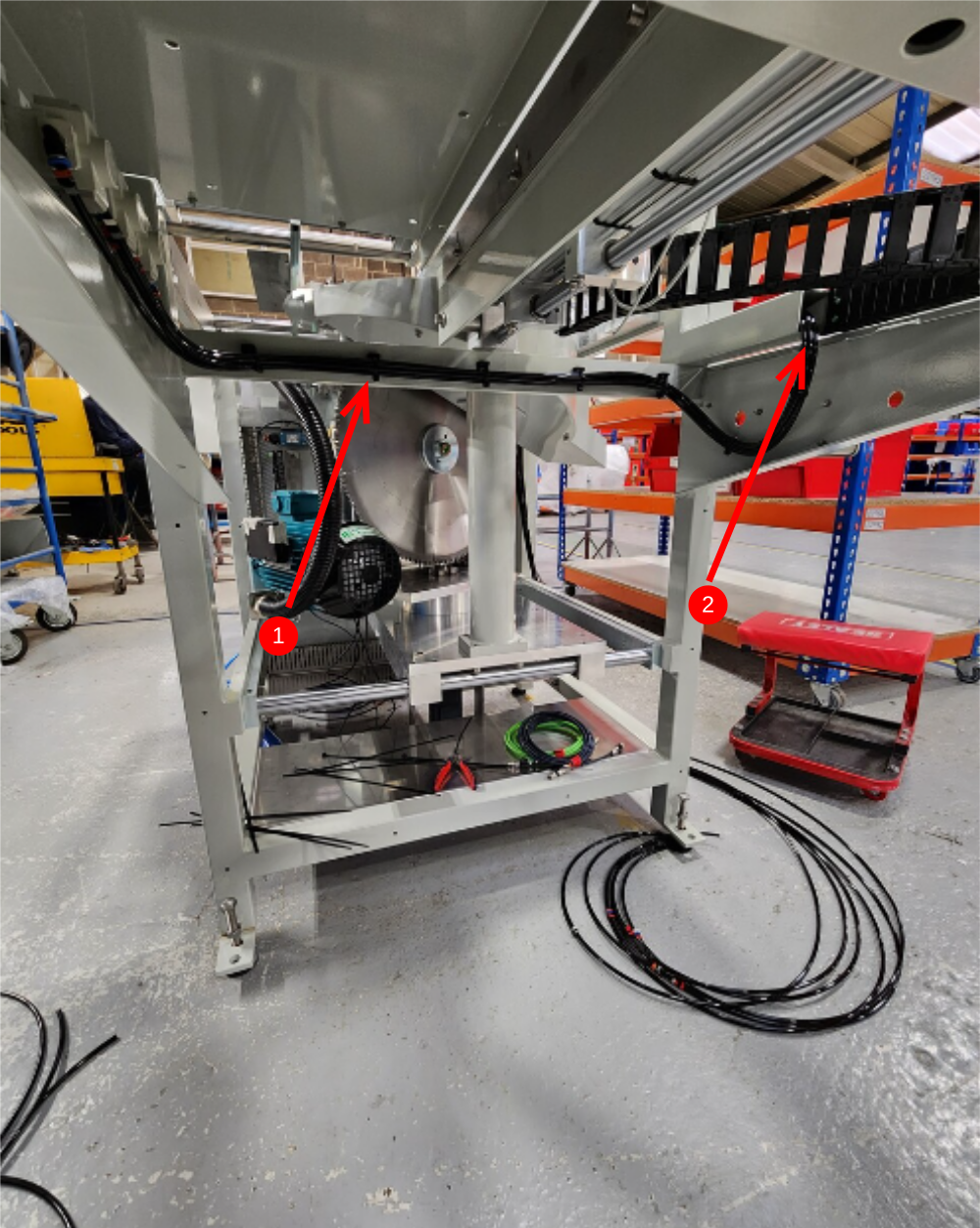
Étape 11 - Loom Cables
Loom cables 24F and EC05f as shown
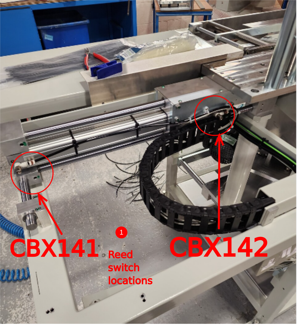
Étape 12 - Y91 Eject reed switches
1 Use reed switches CBX 141 and CBX 142 from loom box
Set in position on eject cylinder using test box . CBX 141 home position CBX142 out position . Reed switches are mounted on bottom face of cylinder
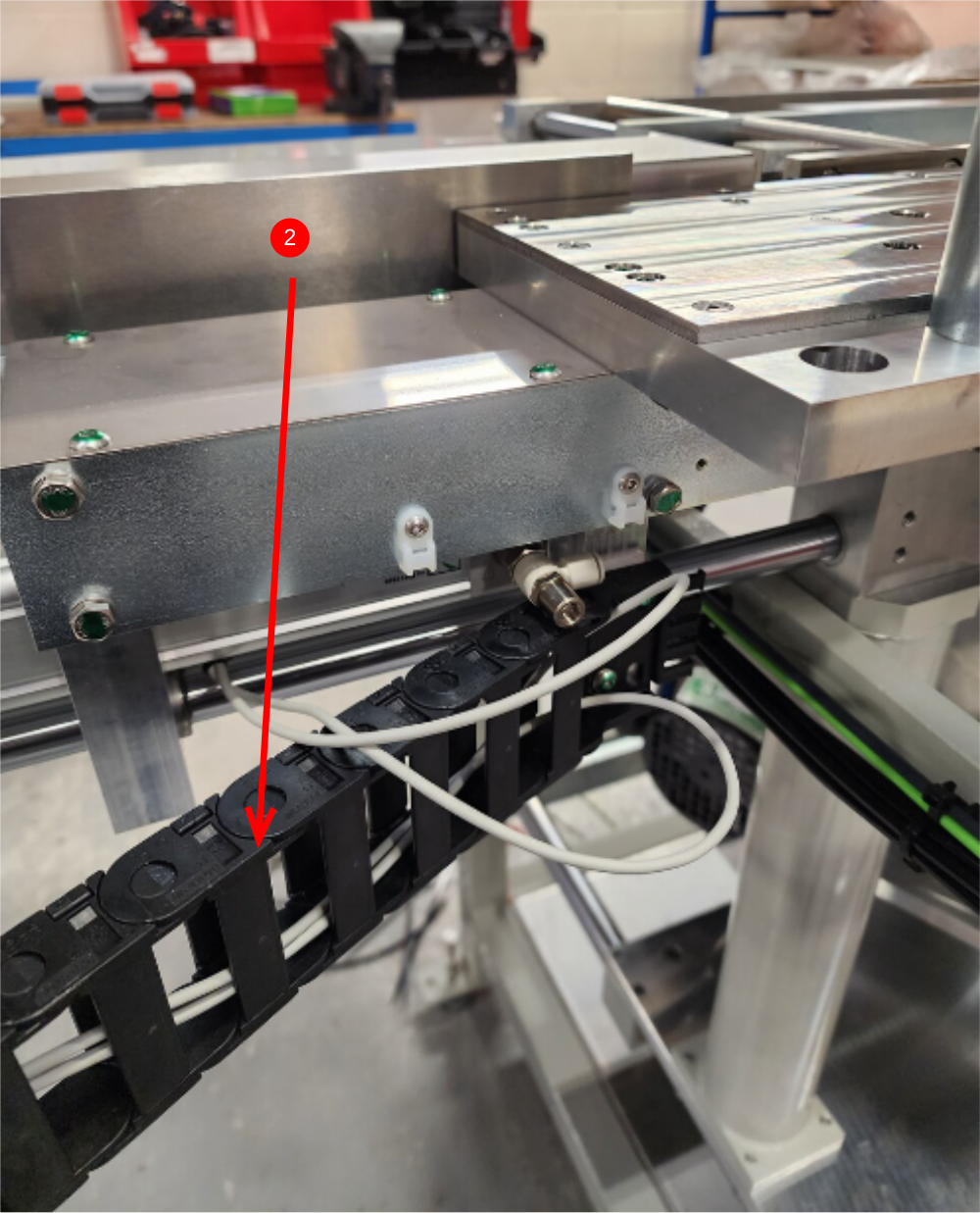
2 Exit cables at point shown
3 loom through energy chain
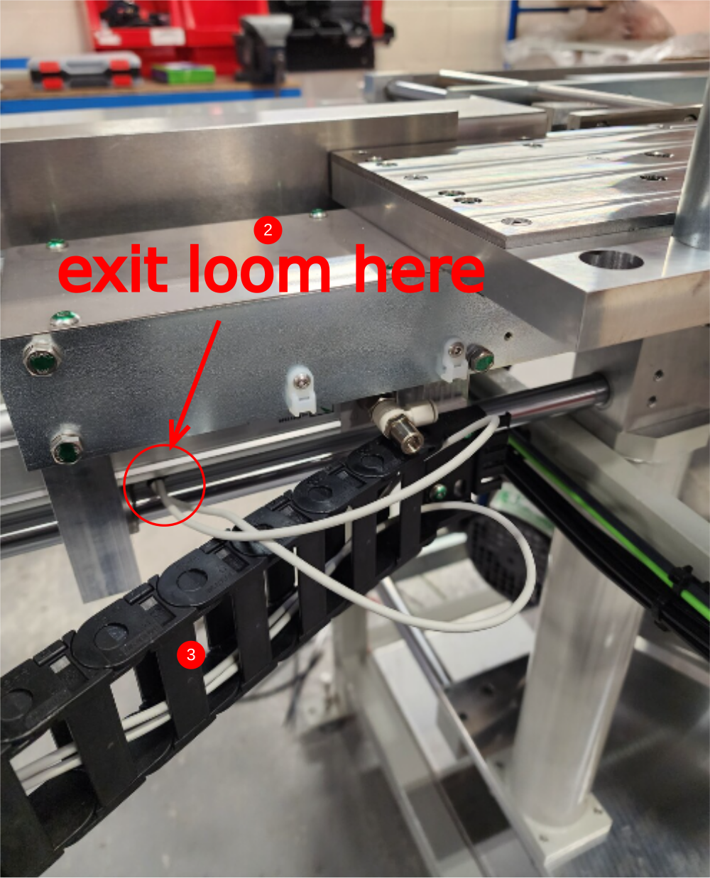
Étape 13 - Y91 Eject pneumatic connections
1 Cut 2 off 6mm black pipes at 4.5 meters long
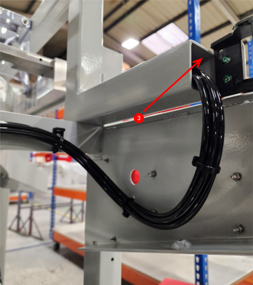
2 Loom through energy chain
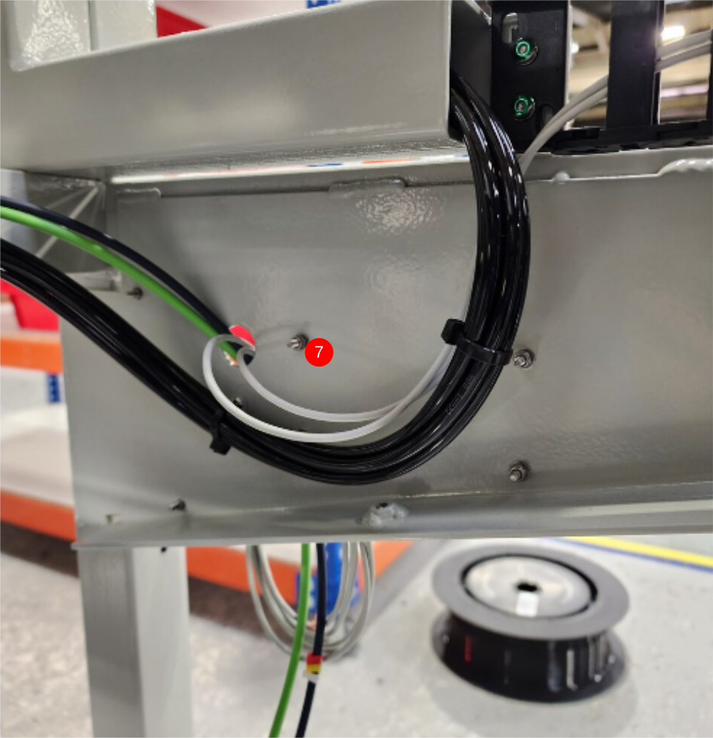
3 Then box section as shown
4 Exit point though cutout
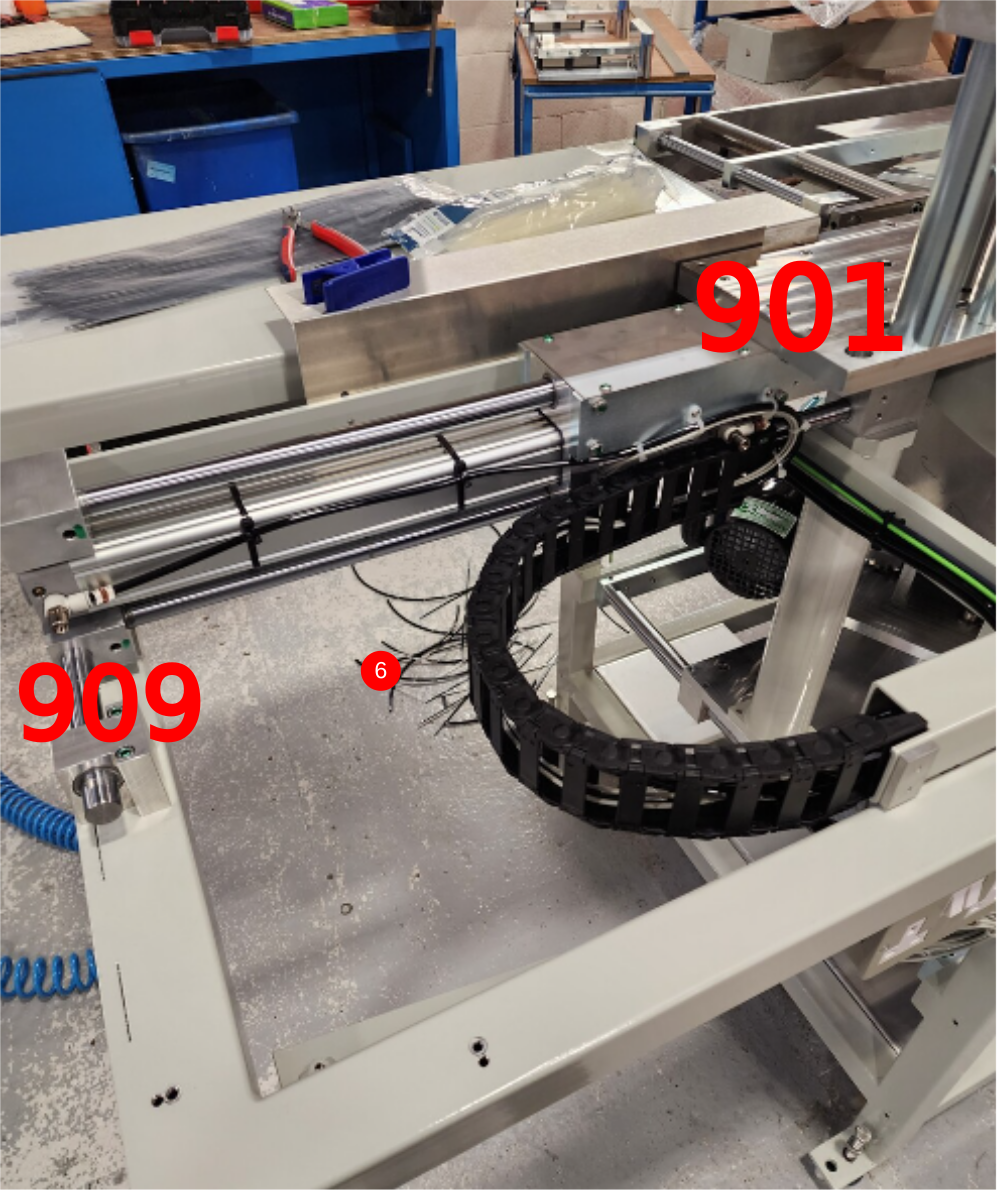
5 Use air to identify pipes as 901 and 909
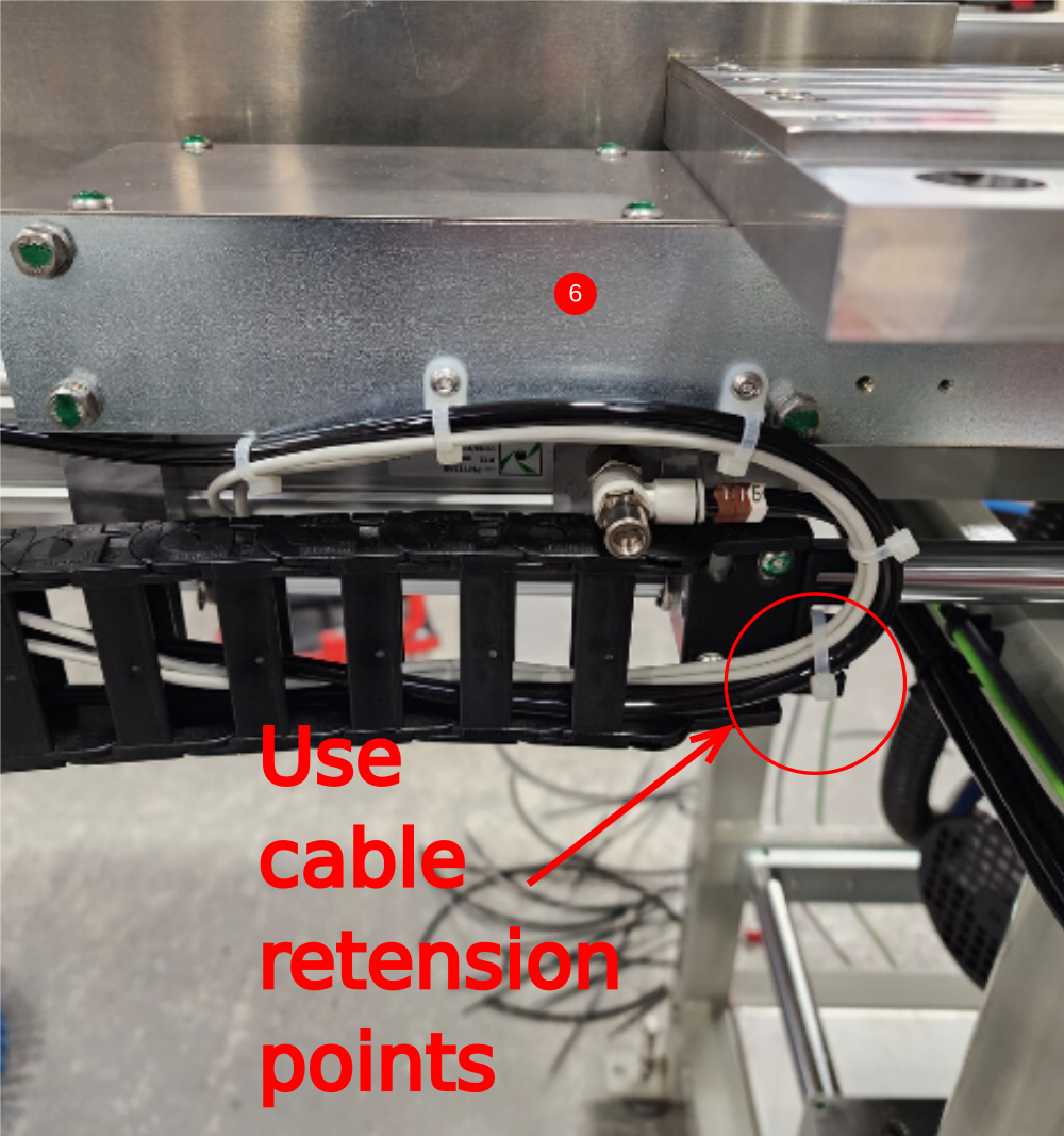
6 Connect eject cylinder as shown . incorporating reed switches into loom
7 Finalise reed switch loom and exit to ethercat box

Étape 14 - Y80 Infeed top clamp
801 valve bank home to cylinder nose
803 to feed cylinder rear port and valve port indicated . P0000551 to be fitted to this line next to cylinder
Draft
 Français
 English
 Deutsch
 Español
 Italiano
 Português